
Summary of Contents for DencoHappel MATRIX OP21C
- Page 1 OPERATION MANUAL Controls and Regulation DencoHappel MATRIX ® Control Panel with Display Regulate efficiently, conserve resources...
-
Page 2: Table Of Contents
MATRIX control panel Table of contents Overview of units and packaged content ..... 4 Using MATRIX control panels ......6 Packaged content . - Page 3 MATRIX control panel Basic operation using the display ..... . . 34 “Setpoint room temperature” menu (basic display 1 – alternatively to basic display 2) 38 “Setpoint supply-air temperature”...
-
Page 4: Overview Of Units And Packaged Content
Overview of units and packaged content MATRIX control panel Overview of units and packaged content OP21C and OP31C OP30C and OP20C OP44C OP50C OP51C Optional: Unit cover OPD.C (not OP5xC) PR-2011-0110-GB • Subject to modifications • R9-03-2016... - Page 5 MATRIX control panel Overview of units and packaged content OP21I and OP31I OP30I OP44I OP50I OP51I Optional: Unit cover OPD.I (not OP5xI) PR-2011-0110-GB • Subject to modifications • R9-03-2016...
-
Page 6: Using Matrix Control Panels
Overview of units and packaged content MATRIX control panel Using MATRIX control panels In combination with the MATRIX controllers, the MATRIX control panels let you specify setpoint values for the room air conditioning as well as the display of sta- tus and error messages. - Page 7 MATRIX control panel Fig. 1-1: DencoHappel product range PR-2011-0110-GB • Subject to modifications • R9-03-2016...
-
Page 8: About This Operation Manual
About this Operation Manual MATRIX control panel About this Operation Manual Availability of the operation manual The current operation manual provides important instructions on the safe and cor- rect handling of the MATRIX control panel. This operation manual applies to operators, building technicians, technical per- sonnel or instructed persons as well as electricians. -
Page 9: Safety
MATRIX control panel Safety Safety The MATRIX control panel is manufactured in accordance with the state-of-the- art engineering standards and established technical safety codes and regula- tions. The MATRIX control panels are for use intended by the manufacturer. Ensure proper and reliable operation of the unit before use. Observe all relevant safety instructions and precautions in the operation manual. -
Page 10: Proper Use
Proper use The MATRIX control panel is specifically designed for controlling air treatment units manufactured by DencoHappel and depending on the equipment version, regulating other units within a building automation system. According to the hardware version, the MATRIX control panel is used: –... -
Page 11: Modifications And Changes
MATRIX control panel will invalidate the CE conformity and void war- ranty. Spare parts Only original DencoHappel spare parts are allowed, since DencoHappel is not lia- ble if third-party spare parts are used. Disposal Equipment and operating supply materials must be disposed of according to the material type in a safe and environmentally friendly manner. -
Page 12: Technical Description
MATRIX control panel Technical Description Product features and functions The MATRIX control panels are designed to control DencoHappel air treatment units and are available in two types: – Series OPxxC (Comfort) for normal environment (IP20) and – Series OPxxI (Industry) for commercial/industrial environment (IP54). -
Page 13: Models Of Matrix Control Panels
MATRIX control panel Technical Description Models of MATRIX control panels Equipment features Setpoint assign- Operating modes/control modes Unit connection Status display Other ment Type OP20C OP21C OP30C OP31C OP44C Menu guided through digital display; automatic OP50C adjustment of menus to the unit equipment Menu guided through digital display;... -
Page 14: Technical Data And Accessories
Technical Description MATRIX control panel Technical data and accessories 30 mm 83 mm 55 mm 83 mm 135 mm 135 mm Type series OPxxC (Comfort) OPxxI (Industry) Area of application Comfort area Industrial area Ambient conditions Allowed ambient temperature 0 °C to 45 °C Allowed storage temperature -10 °C to 65 °C Allowed relative humidity... - Page 15 MATRIX control panel Technical Description 4.3.1 Accessory Items Accessories OPxxI Sensor type 903.454 Mechanical data External dimensions (W/H/D) 50 x 65 x 44 mm Allowed ambient temperature -35 °C to 90 °C Fixation on the wall Weight 60 g Casing color similar to RAL 9016 (traffic white) Application position arbitrary...
-
Page 16: Assembly And Installation
Assembly and Installation MATRIX control panel Assembly and Installation ELECTRICAL HAZARD! The electrical installation and (dis)assembly of the MATRIX control panel may only be carried out by qualified electricians in compliance with the given oper- ation manual and current VDE regulations. •... -
Page 17: Mounting Matrix Op50X/51X Control Panels
MATRIX control panel Assembly and Installation Mounting MATRIX OP50x/51x control panels NOTICE! Use the drilling template for the wall mounting of the MATRIX control panels (see "Drilling Templates" on page 102). Make sure that the mounting plate is not deformed during installation. 5.2.1 Mounting MATRIX OP5xC (IP20) control panel The casing of the MATRIX OP5xC (IP20) control panel is designed for on-wall... - Page 18 Assembly and Installation MATRIX control panel • Route the wires through the opening (1) in the mount- ing plate (2) of the MATRIX control panel. • Secure the mounting plate of the MATRIX control panel on the wall or flush-mounted socket. 5.2.2 Mounting MATRIX OP5xl (IP54) control panel The casing of the OP5xI is suitable for installation on the wall.
- Page 19 MATRIX control panel Assembly and Installation • Route the wires through the membrane grommets (1) into the surface-mounted socket (2) of the MATRIX control panel. • Mount the surface-mounted socket on the wall. • Route the wires through the opening in the mounting plate (1) of the MATRIX control panel.
-
Page 20: Integration Of Matrix Bsz Circuit Board
Assembly and Installation MATRIX control panel Integration of MATRIX BSZ circuit board The MATRIX BSZ circuit board is an intermediate terminal to be used if two wires are connected using one terminal in MATRIX OP5x (IP20 and IP54) control pan- els (necessary for loop-through of the network). - Page 21 MATRIX control panel Assembly and Installation 5.3.2 Mounting MATRIX BSZ in the surface-mounted casing of the MATRIX OP5X I (IP54) control panel • Integrate the circuit board in the surface-mounted sock- et of the MATRIX control panel. • Route the wires through the membrane grommets (1) of the flush-mounted socket (2) and connect the bus cable (refer to 5.5 Cable recommendations MA- TRIX.Net) as follows:...
-
Page 22: Mounting Matrix Op50X/51X Control Panels
Assembly and Installation MATRIX control panel Mounting MATRIX OP50x/51x control panels For connecting the OP50/51 MATRIX control panel only the following cross sec- tions may be used. Conductor type Number of conductors per terminal cross-sections min to max Rigid conductor cross-section 0.22 to 0.5 mm Flexible conductor cross-section 0.22 to 0.5 mm... -
Page 23: Cable Recommendations Matrix.net
MATRIX control panel Assembly and Installation Cable recommendations MATRIX.Net We recommend the following data transfer cable for MATRIX.Net bus system: Total max. line Max. line length with Manufacturer Cable type only MATRIX.Net + supply length [m] branch feeders, to- MATRIX.Net voltage tal [m] ®... - Page 24 Assembly and Installation MATRIX control panel • Use a screwdriver to lock out the front panel and re- move the latter to top of the mounting plate, as shown in the picture. • Press down on the relevant terminals with the screw- driver and pull out the individual cores.
-
Page 25: Commissioning And Testing
MATRIX control panel Commissioning and testing Commissioning and testing Factory settings The MATRIX control panel is preset as follows. The group addresses and the bus termination on the can be changed as required using the relevant switches. Group address Bus terminating resistor Both DIP switches: closed (ON) * If no network consisting of several groups is configured, this setting can be taken over unchanged. -
Page 26: Matrix.net Termination Setting
Commissioning and testing MATRIX control panel MATRIX.Net termination setting If the MATRIX control panel is integrated as first or last unit in the MATRIX.Net the termi- nating resistors must be activated. • Adjust the terminating resistor on the first and last unit of the network as illustrated in the figure. -
Page 27: Testing Operation
MATRIX control panel Commissioning and testing Testing operation IMPORTANT NOTICE! The power supply of the control panel is performed through the power section of the unit to which the control panel is connected. ELECTRICAL HAZARD! Therefore switch on the power supply or power circuitry of the units only after all installation work has been completed! •... -
Page 28: Operating Matrix Control Panel
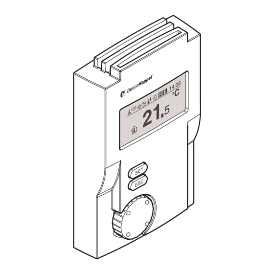
Operating MATRIX control panel MATRIX control panel Operating MATRIX control panel Overview of the operating elements The MATRIX OP5xx control panel is divided into three segments: (1) Display (2) Buttons (3) Navigator (rotation switch) Display The MATRIX control panel is equipped with a monochrome graphical LCD display (1) featuring a resolution of 128 x 64 pixels. -
Page 29: The Menus In Overview
MATRIX control panel Operating MATRIX control panel The menus in overview NOTICE! The selectable menus depend on the version. The menus and their structure can differ depending on the configuration of HVAC equipment and possibly other connected units. 7.2.1 Menu selection In stand-by mode, the MATRIX control panel with display shows the home screen. -
Page 30: Home And Information Screen
Operating MATRIX control panel MATRIX control panel Home and information screen In normal operation the home screen with the “Room temperature” menu is dis- played, or if supply-air temperature control is selected - the “Supply-air tempera- ture” menu. These menus are divided into: –... - Page 31 MATRIX control panel Operating MATRIX control panel Icon Fan mode The fan is controlled by a pressure regulation. The fan is controlled by a volume flow control. The operating mode "Switched off (OFF)" is set: The fan is switched off and cannot be switched on by the control. NOTICE! Applies only for devices with the function "Heating": The control- ler has a "Frost protection function", i.e., if the room temperature...
- Page 32 Operating MATRIX control panel MATRIX control panel Icon Time Control The “Clock timer” operating mode is set. The control is carried out according to the times set in “Clock timer”. A clock module is available in the network: The control is carried out according to the setting via the clock module.
- Page 33 MATRIX control panel Operating MATRIX control panel 7.3.7 “Control indication” icon The “Control indication” icon indicates an external intervention in the control pro- cess by one of two icons. Icon Control display The control or the setpoint assignment is performed from the out- side (remote);...
-
Page 34: Basic Operation Using The Display
Operating MATRIX control panel MATRIX control panel Basic operation using the display The following pages describe the basic operation via the display, based on exam- ples. 7.4.1 Changing values • Select a menu, e.g. “Setpoint room temperature”. • Press the key "SET". The current room temperature setpoint value is displayed inversely and the Change set point line "change setpoint"... - Page 35 MATRIX control panel Operating MATRIX control panel 7.4.2 Changing switching times • Select the “Other menus” menu item. • Press the key "SET". • Select the "Clock timer" menu • Press the key "SET". • Select the "Week program" menu. •...
- Page 36 Operating MATRIX control panel MATRIX control panel • If the second switching period window should not be assigned, then press the “SET” button twice. The starting menu appears. • By pressing the "ESC" button you can always cancel the menu selection.
- Page 37 MATRIX control panel Operating MATRIX control panel 7.4.4 Enabling menu options Example: Activating “Week program” • Select the "Week program" menu. • Select the “enable / disable” menu option. The “enabled” menu option appears, and the cursor stands in front of an Activation option field.
-
Page 38: Setpoint Room Temperature" Menu (Basic Display 1 - Alternatively To Basic Display 2)
Operating MATRIX control panel MATRIX control panel The “YES” field is now highlighted in black. Delete program Really delete? • Press the “SET” button to delete the week program with all switching times. • By pressing the "ESC" button you can always cancel the menu selection. “Setpoint room temperature”... -
Page 39: Setpoint Supply-Air Temperature" Menu (Basic Display 2 - Alternative To Basic Display 1)
MATRIX control panel Operating MATRIX control panel NOTICE! Using the MATRIX.PC service tool control panel, you can select between the setting of an absolute and a relative target value (e.g. +/–3°C) for the room tem- perature. To set a relative target value, an additional base reference value (e.g. with OP71) is required. -
Page 40: Settings For Fan Speed
Operating MATRIX control panel MATRIX control panel Settings for fan speed The options for setting the fan speed with the control panel depend on the unit. A distinction is made whether the control panel is connected to a central air handling unit (compact controls MATRIX 4700) or a decentral unit, e.g. -
Page 41: Menu Setting „Plant/Fan
MATRIX control panel Operating MATRIX control panel If you select the fan mode "level or speed xx%", you can see on the small "Ad- Fan mode ditional pages" icon that there are additional setting options. Automatic Automatic mute Stage 2 •... - Page 42 Operating MATRIX control panel MATRIX control panel 7.9.1 Menu setting "Fan speed" Das "Fan speed" menu appears in combination with the "Plant/Fan" menu and only appears when a manual fan speed setting was selected with the control panel (see the "Fan submenu" on page 71 in chapter 7.21.6 Air handling unit sub- menu).
-
Page 43: Operating Mode" Menu Setting
MATRIX control panel Operating MATRIX control panel 7.9.3 Menu setting "Supply-air volume flow" and/or "Extract-air volume flow" The menus "Supply-air volume flow" or "extract-air volume flow" appear in com- bination with the menu "Plant/fan" and are only shown whenever a fan speed set- ting was selected with volume flow control (see the "Fan submenu"... -
Page 44: Controller Mode" Menu Setting
Operating MATRIX control panel MATRIX control panel Menu Display Explanation option Normal opera- The control system works with the setpoints for tion the normal mode (day operation). Economy The control system works with the set setpoints mode for the economy mode (night operation). Clock Timer Switching between normal mode and economy mode occurs according to the settings of the... -
Page 45: Menu "Secondary-Air Louvre
MATRIX control panel Operating MATRIX control panel Menu Display Explanation option Heating only The control system works exclusively in the heat- ing mode. Cooling is not possible. Cooling only The control system works exclusively in the cool- ing mode. Heating is not possible. Automatic Switching between heating and cooling is carried out automatically by the control system depending... -
Page 46: Menu Setting "Ma Damper Position
Operating MATRIX control panel MATRIX control panel 7.14 Menu setting "MA damper position" The percentage position of the mixing-air dampers can be set in the menu "MA Mixing-air damper position damper position". This menu option appears if the “controlled“ function has been configured on the controller. -
Page 47: Menu Values "Basic Ventilation
MATRIX control panel Operating MATRIX control panel The function of fast ventilation for the entered time can be started in the menu Fast ventilation "Fast ventilation". In this case: – the outside-air damper is opened 100% and – the fan is switched to maximum speed. Value range: 0 ...60 min Possible intervals: 1 min... - Page 48 Operating MATRIX control panel MATRIX control panel 7.20.2 Operation mode "Manual“ In "Manual" mode the user can change the direction of discharge of cold or warm Room air flow air independently of the HVAC-mode (heating or cooling). The air passes parallel Automatic to the ceiling on the right side of the scale and on the left side of the scale, the air Manual...
-
Page 49: Menu "Additional Menus
MATRIX control panel Operating MATRIX control panel 7.20.4 Operation mode "Breath“ The option for the operating mode "Breath" is only displayed on the home screen Room air flow when the plant is designed for cooling function. The operating mode "Breath" is Automatic only available in normal operation for a limited time. - Page 50 Operating MATRIX control panel MATRIX control panel NOTICE! If the faults of warning and information messages could not be corrected during operation, such messages are then automatically removed from the "Operating messages" list. Depending on the type, error messages must be acknowledged (delete status message) or they are likewise automatically removed from the list of "Operation messages".
- Page 51 MATRIX control panel Operating MATRIX control panel Week program submenu Entries are made in the “week program” submenu: Week program – for enabling or disabling the week program (without changing switching times) Enable/disable – for more details see "Enabling menu options" on page 37. Delete program –...
- Page 52 Delete program Thus, it is possible to assign settings for every month of the year and for any num- operating mode ber of days so that the DencoHappel air treatment units: January – should be switched off completely or – should be switched on only in economy mode.
- Page 53 – to specify the operating mode; enter the days in the “Holiday program” for the Operating mode months of January to December on which the DencoHappel air treatment units Switch off unit should be switched off for the whole day or switched over to the “economy Plant economy mode mode”...
- Page 54 Operating MATRIX control panel MATRIX control panel Value range: 1st line: Monday to Sunday or “disabled”* 2nd line: Time from 00:00 to 23:59 or “--:--”*. Factory setting: Monday and 02:00 If “Disabled” or “--:--“ is selected, then the block-up protec- tion is switched off.
- Page 55 MATRIX control panel Operating MATRIX control panel Display Meaning Unit Mlk-Pos Position of the mixing-air damper in % SupPress Current supply-air duct pressure in Pa ExtPress Current extract-air duct pressure in Pa SupVolum Supply-air volume flow in m³/h ExtVolum Extract-air volume flow in m³/h * These values are only shown for central air handling- and flat units.
- Page 56 Operating MATRIX control panel MATRIX control panel Configure ➜ Lighting In the “Configure" menu item, you can change the LCD display backlighting as fol- Configure lows. Permanent on Value range: Backlighting “off”, “permanent on”or “time controlled”; with Time controlled “time controlled” the backlighting is switched off after the last el- ement is operated with a time delay (20 seconds).
- Page 57 You can set the bypass time in the “Set bypass time” submenu. This is the time Set bypass time when the DencoHappel HVAC equipment is operated in normal operation (day operation), even though an external control was switched over from economy Time in minutes mode (night operation) or standby.
- Page 58 Operating MATRIX control panel MATRIX control panel Economy mode submenu In the submenu "Economy mode", the setpoint values are entered depending on Economy mode the controller configuration that are valid during the economy mode (night opera- Room temperature tion), and namely for: Supply air temperature Fan mode Central and decentralized air...
- Page 59 MATRIX control panel Operating MATRIX control panel Fan speed in economy mode The options for setting the fan speed with the control panel depend on the unit. A distinction is made whether the control panel is connected to a central air handling unit (compact controls MATRIX 4700) or a decentral unit.
- Page 60 Operating MATRIX control panel MATRIX control panel one of the following types of fan control was selected at air handling units: – External fan speed setting e.g. by means of potentiometer with 0-10°V signal – Manual fan speed setting with control panel (see also Economy mode Ü Fan speed on Page 60), –...
- Page 61 MATRIX control panel Operating MATRIX control panel NOTICE! The speed setting can be influenced by the minimum and maximum permissi- ble speed saved in the controller or the frequency converter. The values in the controller can be changed with the help of the MATRIX.PC service soft- ware.The values of the frequency converter can be changed using the control panel of the power inverter.
- Page 62 Operating MATRIX control panel MATRIX control panel The supply-air and/or extract-air volume flow is set absolutely in m³/h. In order to Supply-air volume flow avoid faulty entries, the minimal and maximum adjustable setpoint can be m³/h changed with the MATRIX.PC service tool. 3750 Value range: to 65,000 m³/h (factory setting)
- Page 63 MATRIX control panel Operating MATRIX control panel NOTICE! The passive cooling function con not be activated in connection with air quality regulation, it can only perform with a room temperature control. There is no effect for all other types of control. Economy mode ➜...
- Page 64 Operating MATRIX control panel MATRIX control panel Value range: 0 ...100 % (for continuous dampers) Possible intervals: 5 % Factory setting: 0 % Variant 0 or 100 % (for open/close dampers) Factory setting: 0 % Economy mode ➜ outside air volume flow In the "Outside-air volume flow”...
- Page 65 MATRIX control panel Operating MATRIX control panel Calibrate discharge submenu You can calibrate the louvre angle in this submenu for units with controlled louvre. Calibrate discharge The menu window shows on the left side: Tm: 42,4°C – the current flow temperature Tm Stop To: 9,4°C –...
- Page 66 Operating MATRIX control panel MATRIX control panel The "MA damper" submenu allows you to enter the settings for the mixing-air Mixing-air damper mode damper. Manual Air volume flow Value Manual, air volume flow, automatic, autom.+fan Automatic range: Factory setting: unit-dependent Autom.+fan In “manually operated”...
- Page 67 MATRIX control panel Operating MATRIX control panel Value 0–9999 range: Adjustable steps: 50 Factory setting: 400 - 1800 Air flush submenu NOTICE! The "Air flush function" submenu does not appear when using the MATRIX 4700 central or low-profile control system. The "Air flush function"...
- Page 68 Operating MATRIX control panel MATRIX control panel NOTICE! If less that 1°C or more that 49°C value range is defined, the initiation of active operating mode will be prevented. Minimum outside-air rate submenu You can determine the minimum permissible outside-air rate in the menu item Minimum outside-air rate "Minimum outside-air rate".
- Page 69 MATRIX control panel Operating MATRIX control panel The Geko-DRIVE is only calibrated on one unit per group. Upon completion of the calibration these settings are then copied to all other units in a group. Calibration process After entering the menu, the current air throw is graphically presented in the form Cal.
- Page 70 Operating MATRIX control panel MATRIX control panel the settings. The control purpose is to reach the required room air flow by chang- ing the SWIRL-outlet. • In order to do this, use the navigator to change the setting. The desired air throw aimed is shown on the x-axis by a broken line cursor. Only when both cursors cover the marks, the actuator reaches the desired position.
- Page 71 MATRIX control panel Operating MATRIX control panel EQUIPMENT DAMAGE! It is mandatory to make the above-listed configurations (insofar as the individ- ual unit functions are available). Otherwise, a correct functioning of the control or the central air handling unit cannot be ensured. Control mode submenu The following unit types can be selected in the "Unit Type"...
- Page 72 Operating MATRIX control panel MATRIX control panel Supply-air fan Extract-air fan Display Control mode Display Control mode Temp. Temperature controlled -------- Without extract-air fan Temp. Temperature controlled Offset Extract-air fan follows supply-air fan with speed offset Temp. Temperature controlled Factor Extract-air fan follows supply-air fan with factor Duct pres-...
- Page 73 MATRIX control panel Operating MATRIX control panel Supply-air fan Extract-air fan -------- Without supply-air fan Speed.OP Assignment of fan speed using control panel Offset Supply-air fan follows extract-air fan with Speed.OP Assignment of fan speed using control speed offset panel Factor Supply-air fan follows extract air fan with Speed.OP Assignment of fan speed using control...
- Page 74 Operating MATRIX control panel MATRIX control panel 100% Speed of slave fan with factor 2 Speed of slave fan with factor 1.5 Speed master fan Speed of slave fan with factor 0.5 Speed of slave fan with factor 0.25 100% Value range: -50% to 50% Adjustable steps: 1%...
- Page 75 MATRIX control panel Operating MATRIX control panel Fans ➜ Max. volume flow The maximum volume flow or the maximum volume flows in m³/h of the con- Max. volume flow nected air handling unit must be entered by selecting "supply air fan" or extract Supply-air fan air fan"...
- Page 76 Operating MATRIX control panel MATRIX control panel Display Type of damper Automatic 2-point 2-point damper Autom.+fan 2-P. 2-point damper Automatic 3-point 3-point damper Autom.+fan 3-P. 2-point damper NOTICE! Notice: Description of the dampers control type, see "Submenu MA damper mode" on page 65. Electric heating submenu The following types of electrical heating can be selected in the "Electric heating"...
- Page 77 MATRIX control panel Operating MATRIX control panel Sensor input submenu The sensor inputs for air handling units for continuously variable speed control of Sensor inputs the required fans are configured in the submenu "Sensor inputs". Sensor inputs Supply-air fan are used with external assignment of fan speed using a 0-10V signal, with fan Extract-air fan speed assignment via duct pressure control and volume flow control.
- Page 78 Operating MATRIX control panel MATRIX control panel Sensor inputs ➜ Input type If the following points are selected in the "Use" submenu: Input type – Measuring duct pressure 0..10 Volt – Measuring volume flow 2..10 Volt – Volume flow measurement with pressure sensor the suitable voltage range for the used sensor can be selected in the submenu "input type".
- Page 79 MATRIX control panel Operating MATRIX control panel Example range start/range The supply-air fan speed and supply-air volume can be changed using an exter- end: nal 0-10V signal. The following settings are selected: – Use: Speed setpoint over 0-10V [speed setpoint] –...
- Page 80 Versions Info and software version of the MATRIX control panel. Serial #: 0001 The version information is important, for instance, when ordering spare parts or Firmware: OP51C 1.00 calling the DencoHappel service hotline. Hardware: 1.00 Bus system: 1.00 Designation Explanation Serial #: XXXX Serial No.
- Page 81 MATRIX control panel Operating MATRIX control panel 7.21.8 Full blocking submenu If you select the "Full blocking" menu option in “Additional menus”, you have to Full blocking enter your password first. Enter password Factory setting: 0000 **** Now the basic menu with a key is displayed. Operation is no longer possible. Cancel full blocking If you activate one of the buttons or the navigator, the password menu opens again.
-
Page 82: Maintenance, Cleaning And Troubleshooting
Maintenance, Cleaning and Troubleshooting MATRIX control panel Maintenance, Cleaning and Troubleshooting Maintenance The MATRIX control panel is maintenance-free. Cleaning Perform the following work at regular intervals: • Clean the MATRIX control panel only with a soft cloth. • Check the casing as well as the operating elements and if necessary the digital display for damage. - Page 83 MATRIX control panel Maintenance, Cleaning and Troubleshooting 8.3.1 Operating messages of the MATRIX control panels ➜ Group Code Text Type Confirmation Description Remedy (FC) needed Internal An internal error has occurred which the user cannot re- solve. ➜ Please contact an authorized service center and errors error describe the fault message.
- Page 84 Maintenance, Cleaning and Troubleshooting MATRIX control panel ➜ Group Code Text Type Confirmation Description Remedy (FC) needed Continu- Inlet sensor The inlet temperature sensor is defective. ➜ Check connection to the sensor, possible cable break or ation: missing sensor missing, even though the control fault (software) requires a sensor.
- Page 85 MATRIX control panel Maintenance, Cleaning and Troubleshooting ➜ Group Code Text Type Confirmation Description Remedy (FC) needed Continu- Motor protec- Frequency converter of the extract-air fan notifies a mal- function. ➜ Check the frequency converter and the thermal ously tion 2 has trig- variable gered! contact or resistor of the motor.
- Page 86 Maintenance, Cleaning and Troubleshooting MATRIX control panel ➜ Group Code Text Type Confirmation Description Remedy (FC) needed * F = Fault; M = Maintenance; I = Information Electric Safety tem- Safety temperature limiter has triggered. ➜ Check air supply/filter (see also operation manual of the heater perature limit- er triggered...
- Page 87 MATRIX control panel Maintenance, Cleaning and Troubleshooting ➜ Group Code Text Type Confirmation Description Remedy (FC) needed Data for the control of the mixing-air damper is missing. ➜ Continu- 13.10 MAD data ation: missing Check connection of the feedback potentiometer (for con- Operat- nection, see operation manual of the air treatment unit or ing error...
- Page 88 Maintenance, Cleaning and Troubleshooting MATRIX control panel ➜ Group Code Text Type Confirmation Description Remedy (FC) needed Continu- 14.0 Address con- An address conflict has occurred. Ô A second control pan- ation: flict el with the same address is connected in the group. In Operat- some cases a group can have 2 fan modules or 2 direct ing error...
-
Page 89: Menu Structure Op5Xx
MATRIX control panel Menu Structure OP5xx Menu Structure OP5xx All possible menus are shown in this menu structure. According to the configuration of the controller some menus can exclude one another or not appear at all. − Basic menu Setpoint →... - Page 90 Menu Structure OP5xx MATRIX control panel Other menus (continued) Clock timer (continuation) → → − → Special days ( − Activation − Delete program − 1. <--.--.----> − 6. <--.--.----> − → Holiday programme ( − Activation − Delete program −...
- Page 91 MATRIX control panel Menu Structure OP5xx Other menus (continued) Settings (continued) → → − → economy mode ( − → Room temperature ( − → Supply air temperature ( − − Automatic → Fan mode ( Auto (mute) Speed xx %/stage x −...
- Page 92 Menu Structure OP5xx MATRIX control panel − Other menus (continued) → Air handling unit → Unconfigured − − Heating only → Unit type ( Cooling only Heating+cooling Unconfigured − − Room temperature → Control mode ( Supply-air temperature Room/supply air - cascade Control mode −...
-
Page 93: 10 Index
MATRIX control panel Index 10 Index Numerics 12-hour display 24-hour display About this Operation Manual Accessories OPxxI Actual values Additional menus Adjust brightness Adjust louvre Menu Air flush function Air handling unit Air quality Air volume All week days Alterations of MATRIX control panel Ambient conditions Application position Area of application... - Page 94 OP44C OP50C OP50l OP51C OP51l Controller Mode icons Controller mode Controls Date Date/time icons Day operation Deleting settings DencoHappel spare parts Disassembly control panel IP54-casing Display Idle state OP5xx operation Display backlight Display idle mode Disposal Drilling template OPxxC OPxxI...
- Page 95 MATRIX control panel Index Economy mode Edit bypass time Electrical data Electromagnetic compatibility Electromagnetic immunity Electromagnetic interference, electromagnetic emissions Enabling menu options Equipment features Error messages OP5xx Explanation of safety instructions Explanation of symbols Explanation of the symbols External dimensions Factory delivery condition Factory settings Fan mode...
- Page 96 Index MATRIX control panel Status message Time control Improper use Information display Information display icons Installation OP50x/51x Installation height Installation location IP20 IP54 LCD display Changing contrast Limits of supply-air temperature Louvre angle offset Louvre calibration Maintenance MATRIX control unit OP5xx testing MATRIX.Net termination setting Mechanical data Menu...
- Page 97 MATRIX control panel Index mixing-air damper operation during economy mode Mixing-air damper position Models of MATRIX control panels Modifications Mounting OP5xC (IP20) OP71I (IP54) planning Navigator OP5xx Night operation Normal operation OP21C OP21I OP30C OP30I OP31I OP44C OP44I OP50C OP50I OP50x/51x install OP51C...
- Page 98 Index MATRIX control panel Operation using the display operation OP5xx Operation messages OPxxC Drilling template OPxxI Drilling template Outdoor-air volume flow Outside air automatic Outside air control icons Overview of the operating elements OP5xx Packaged content Partial blocking Password forgotten Full blocking Partial blocking Penetration calibration...
- Page 99 MATRIX control panel Index Safety Safety instructions Safety-conscious work procedures Safety-conscious working Scope of the operation manual Secondary-air louvre Select language Select menu Selection of personnel Sensor Sensor correction Sensor offset value Service Set bypass time Setpoint Room temperature Room temperature (menu) supply-air temperature Setpoint supply-air temperature (menu) Setting...
- Page 100 Index MATRIX control panel Configuration Date/time Error list Fan lowest speed Full blocking Holiday program MA damper position minimum outside-air rate Partial blocking Password change Quiet operation speed Sensor offset value Service Set clock Setting for room air flow (SWIRL) Status message summertime automatics supply temperature limits...
- Page 101 MATRIX control panel Index Heating Temperature limits of heating operation Temperature Unit Test MATRIX OP5xx control unit Testing operation The menus in overview Time Time control icons Time format Unit cap Unit for temperature displays Unit overview Used symbols Using MATRIX control panels Versions Info Week program Weight...
-
Page 102: Drilling Templates
Drilling Templates MATRIX control panel Drilling Templates 11.1 Unit version OPxxC (IP 20) 11.2 Unit version OPxxI (IP 54) PR-2011-0110-GB • Subject to modifications • R9-03-2016... - Page 103 MATRIX control panel Drilling Templates PR-2011-0110-GB • Subject to modifications • R9-03-2016...
- Page 104 DencoHappel is a global company with expertise in air treatment, air conditioning and air filtration. Our nearest sales and service teams will be glad to discuss ideas and develop creative and effective solutions with you. www.dencohappel.com...
Need help?
Do you have a question about the MATRIX OP21C and is the answer not in the manual?
Questions and answers