HPE ProLiant MicroServer Gen10 Plus User Manual
Hide thumbs
Also See for ProLiant MicroServer Gen10 Plus:
- Product end-of-life disassembly instructions (5 pages) ,
- User manual (60 pages) ,
- User manual (81 pages)
Table of Contents
Advertisement
HPE ProLiant MicroServer Gen10 Plus User
Guide
Abstract
This document is for the person who installs, administers, and troubleshoots servers and storage systems.
Hewlett Packard Enterprise assumes you are qualified in the servicing of computer equipment and trained in
recognizing hazards in products with hazardous energy levels.
Part Number: P19356-001
Published: February 2020
Edition: 1
Advertisement
Table of Contents

Related Manuals for HPE ProLiant MicroServer Gen10 Plus


Summary of Contents for HPE ProLiant MicroServer Gen10 Plus
- Page 1 HPE ProLiant MicroServer Gen10 Plus User Guide Abstract This document is for the person who installs, administers, and troubleshoots servers and storage systems. Hewlett Packard Enterprise assumes you are qualified in the servicing of computer equipment and trained in recognizing hazards in products with hazardous energy levels.
- Page 2 © Copyright 2020 Hewlett Packard Enterprise Development LP Notices The information contained herein is subject to change without notice. The only warranties for Hewlett Packard Enterprise products and services are set forth in the express warranty statements accompanying such products and services. Nothing herein should be construed as constituting an additional warranty.
-
Page 3: Table Of Contents
Removing the system board assembly................................20 Installing the system board assembly................................22 Setup..........................24 Optional service..........................................24 Initial system installation......................................24 HPE Installation Service..................................24 Setting up the server....................................25 Server orientation options.......................................30 Position the server in a horizontal orientation...........................30 Position the server in a vertical orientation..........................30 Operational requirements......................................32... - Page 4 Installing the iLO enablement option..............................54 HPE Trusted Platform Module 2.0 Gen10 option.............................56 Overview...........................................56 HPE Trusted Platform Module 2.0 guidelines........................... 56 Installing and enabling the HPE TPM 2.0 Gen10 option....................57 Cabling..........................62 Cabling overview ..........................................62 Storage cabling..........................................62 Four-bay drive cabling: Onboard SATA controller cabling....................62 Four-bay drive cabling: Smart Array controller cabling......................63...
- Page 5 Safety and security benefits................................. 73 Keeping the system current....................................73 Updating firmware or system ROM..............................73 Drivers..........................................76 Software and firmware.....................................76 Operating system version support..............................76 HPE Pointnext Portfolio..................................76 Proactive notifications....................................77 Troubleshooting......................78 NMI functionality...........................................78 Troubleshooting resources..................................... 78 System battery replacement..................79 System battery information....................................79 Removing and replacing the system battery..............................79...
-
Page 6: Component Identification
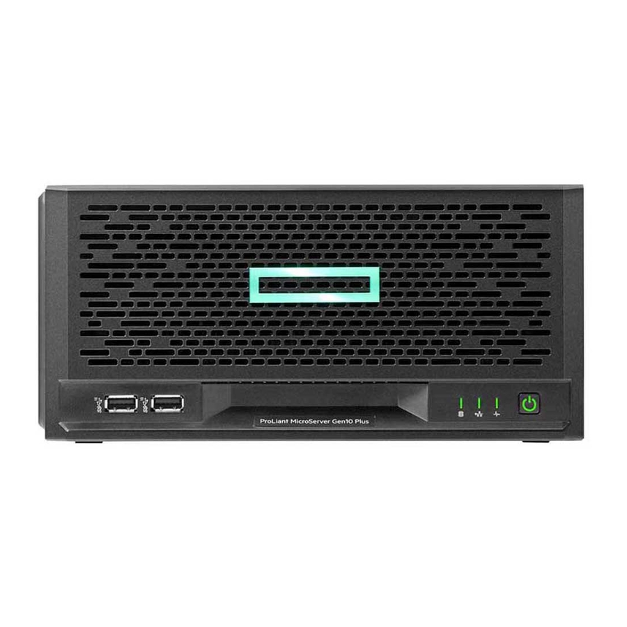
Component identification This chapter describes the external and internal server features and components. Front panel components Item Component Description Drive bays (4, behind the front bezel) By default, the drive bays support 3.5-inch LFF SATA drives. To support 2.5-inch SFF drives, install the SFF drive converter option. -
Page 7: Front Panel Leds And Button
Front panel LEDs and button Item Description Status Definition Drive activity LED Flashing green Ongoing drive activity No drive activity 2, 3 NIC status LED Solid green Linked to network Flashing green Network active No network activity Health LED Solid green Normal Flashing green iLO is rebooting... -
Page 8: Rear Panel Components
2 flashes Memory 3 flashes Riser board PCIe slots 4 flashes FlexibleLOM 5 flashes Removable HPE Smart Array SR Gen10 controller 6 flashes System board PCIe slots 7 flashes Power backplane or storage backplane 8 flashes Power supply 9 flashes... -
Page 9: Rear Panel Leds
Component Description System QR code label To access the server mobile product page (https://www.hpe.com/ qref/microservergen10plus), use a QR code scanner app in your smartphone to scan this label. This mobile page contains links to server setup information, spare part numbers, QuickSpecs, troubleshooting resources, and other useful product links. -
Page 10: System Board Components
No network activity System board components Item Component Description TPM connector This connector supports the HPE Trusted Platform Module 2.0 Gen10 option (864279-B21) for data security. Fan connector Connects the fan cable. Riser connector Connects the system riser board. System maintenance switch Use this switch to physically configure various server settings. -
Page 11: System Maintenance Switch Descriptions
System maintenance switch descriptions Position Default Function Off = iLO 5 security is enabled. On = iLO 5 security is disabled. Reserved Reserved Reserved Off = Power-on password is enabled. On = Power-on password is disabled. 1, 2, 3 Off = No function On = Restore default manufacturing settings Reserved —... - Page 12 Item Description Example Capacity 8 GB 16 GB 32 GB 64 GB 128 GB Rank 1R = Single rank 2R = Dual rank 4R = Quad rank 8R = Octal rank Data width on DRAM x4 = 4-bit x8 = 8-bit x16 = 16-bit Memory generation PC4 = DDR4...
-
Page 13: Drive Bay Numbering
For more information about product features, specifications, options, configurations, and compatibility, see the HPE DDR4 SmartMemory QuickSpecs on the Hewlett Packard Enterprise website (https://www.hpe.com/support/ DDR4SmartMemoryQS). Drive bay numbering Drive screws There are 16 T-15 Torx screws located under the drive bays. Use these screws to install drives in the server. -
Page 14: Riser Board Slots
Install the iLO enablement option here. PCIe3 ×16 expansion slot Install a half-height PCIe3 ×16 expansion board here. See the product QuickSpecs on the server website at https:// www.hpe.com/servers/microserver for list of supported expansion options. Component identification... -
Page 15: Operations
Operations This chapter describes the hardware operations carried out prior to and after installing or removing a hardware option, or performing a server maintenance or troubleshooting procedure. Before performing these hardware operations, review and observe the server warnings and cautions. Power up the server To power up the server, use one of the following methods: •... - Page 16 6. If the front bezel is locked, do the following: a. Remove the chassis cover. b. Switch the bezel locks upward. 7. To remove an unlocked front bezel, do the following: a. Pivot the bottom part of the bezel upward (callout 1). b.
-
Page 17: Installing The Front Bezel
Installing the front bezel Procedure 1. Make sure that the bezel locks are in the unlocked position. 2. Install the front bezel: a. Insert the bezel tabs to their chassis openings (callout 1). b. Pivot the bottom part of the bezel downward (callout 2). Operations... -
Page 18: Removing The Chassis Cover
3. If you prefer to secure the bezel to the chassis, switch the bezel locks downward. 4. If removed, install the chassis cover. 5. If removed, install the security padlock and/or the Kensington security lock. For more information, see the lock documentation. 6. - Page 19 Procedure 1. Power down the server. 2. Disconnect the power cord from the AC source. 3. Remove the power adapter cord from the power cord clip, and then disconnect the power adapter from the server. 4. Disconnect all peripheral cables from the server. 5.
-
Page 20: Installing The Chassis Cover
Installing the chassis cover Procedure 1. Install the chassis cover: a. Insert the cover tabs to their chassis openings. Make sure that the cover is flushed against the top of the chassis. b. Slide the chassis cover towards the front panel (callout 1), and then install the chassis thumbscrews (callout 2). 2. - Page 21 Prerequisites Before you perform this procedure, make sure that you have a T-15 Torx screwdriver available. Procedure 1. Power down the server. 2. Disconnect the power cord from the AC source. 3. Remove the power adapter cord from the power cord clip, and then disconnect the power adapter from the server. 4.
-
Page 22: Installing The System Board Assembly
IMPORTANT: The storage cables connect the system board to the chassis. If you are completely separating the system board assembly from the chassis, disconnect the storage cabling. 9. Use the blue touchpoints on both sides of the tray to pull out the system board assembly from the chassis. Installing the system board assembly Prerequisites Before you perform this procedure, make sure that you have a T-15 Torx screwdriver available. - Page 23 3. If removed, install the internal USB device. 4. Install the chassis cover. 5. If removed, install the security padlock and/or the Kensington security lock. For more information, see the lock documentation. 6. Connect all peripheral cables to the server. 7.
-
Page 24: Setup
HPE-supported products from other vendors that are sold by HPE or by HPE authorized resellers. The Installation Service is part of a suite of HPE deployment services that are designed to give users the peace of mind that comes from knowing that their HPE and HPE-supported products have been installed by an HPE specialist. -
Page 25: Setting Up The Server
Full coverage during the warranty period for products that require installation by an HPE authorized technical specialist. For more information on the features, limitations, provisions, and ordering information of the HPE Installation Service, see this Hewlett Packard Enterprise website: https://www.hpe.com/support/installation-service... - Page 26 The server does not ship with OS media. All system software and firmware is preloaded on the server. Install the hardware options (Optional) Install the hardware options. For installation instructions, see the server user guide on the HPE website: https://www.hpe.com/info/microservergen10plus-docs...
- Page 27 d. Close the power cord clip until it clicks into place. Decide how to manage the server: • Locally: Use a KVM switch or a connect a keyboard, monitor, and mouse. Setup...
- Page 28 This action requires the iLO enablement option for remote iLO access. a. Verify the following: ◦ iLO is licensed to use the remote console feature. If iLO is not licensed, visit the HPE website: https://www.hpe.com/info/ilo ◦ The iLO dedicated or shared network port is connected to a secure network.
- Page 29 Press F10 at the POST screen. • You are prompted to select whether you want to enter the Intelligent Provisioning or HPE Rapid Setup Software mode. After you have selected a mode, you must reprovision the server to change the mode that launches when you boot to F10.
-
Page 30: Server Orientation Options
Server orientation options The server can be oriented in a horizontal or vertical setup depending on the available space in the installation site. Position the server in a horizontal orientation There are four antislip rubber pads preinstalled on the base of the server for a horizontal setup. In a horizontal setup, you can stack up to three MicroServers on top of each other. - Page 31 Prerequisites Before you perform this procedure, make sure that you have the following items available: • Isopropyl alcohol wipe • Antislip rubber strips Procedure 1. Use an isopropyl alcohol wipe to clean the divots on the side of the server. Allow the alcohol to evaporate before continuing.
-
Page 32: Operational Requirements
Operational requirements Site requirements The server may be located in an office space or a purpose-made equipment room. The location must: • Comply with local health and safety regulations. • Be clean, tidy, and free of excessive dust and vibration. •... -
Page 33: Power Requirements
CAUTION: To reduce the risk of damage to the equipment when installing third-party options: • Do not permit optional equipment to impede airflow around the server or to increase the internal rack temperature beyond the maximum allowable limits. • Do not exceed the manufacturer’s TMRA. Power requirements Installation of this equipment must comply with local and regional electrical regulations governing the installation of information technology equipment by licensed electricians. -
Page 34: Electrostatic Discharge
CAUTION: To prevent improper airflow and insufficient cooling that can lead to thermal damage, observe the following: • Do not operate the server with the front bezel or chassis cover removed. • Periodically clean the dust filter on the inner surface of the front bezel. CAUTION: To prevent damage to electrical components, properly ground the server before beginning any installation procedure. -
Page 35: Installing Or Deploying An Operating System
Before installing an operating system, observe the following: • Be sure to read the HPE UEFI requirements for ProLiant servers on the Hewlett Packard Enterprise website. If UEFI requirements are not met, you might experience boot failures or other errors when installing the operating system. -
Page 36: Hardware Options Installation
Hardware options installation This chapter provides detailed instructions on how to install hardware options. For more information on supported options, see the product QuickSpecs on the HPE ProLiant MicroServer Gen10 Plus website at: https://www.hpe.com/servers/microserver To view the warranty for your server and supported options, see Warranty information. -
Page 37: Installing An Lff Drive
Installing an LFF drive The LFF drives supported in this server do not require a drive caddy or a drive carrier to install. You only have to use the drive mounting screws on the chassis. Prerequisites Before you perform this procedure, make sure that you have a T-15 Torx screwdriver available. Procedure Power down the server. - Page 38 Install the screws in the drive. 10. Slide the drive into the bay until it clicks into place. 11. Install the front bezel. 12. Connect all peripheral cables to the server. 13. Connect the power adapter to the server, and then secure the power adapter cord in the power cord clip. 14.
-
Page 39: Installing An Sff Drive
The installation is complete. To configure arrays, see the HPE Smart Array SR Gen10 Configuration Guide at the Hewlett Packard Enterprise website. Installing an SFF drive To install SFF hard drives and SSDs, use the SFF-to-LFF drive converter option. In general, SFF hard drives require as little as half the power and generate significantly less heat than LFF hard drives. - Page 40 Remove the front bezel. Install the SFF drive in the drive converter tray. Follow the callout sequence in the following illustration to install the screws included in the converter kit on the bottom side of the drive converter tray. Hardware options installation...
- Page 41 10. Remove three drive screws from the front panel. 11. Install the three screws removed from the front panel on the left and right sides of the drive converter tray. Hardware options installation...
-
Page 42: Memory Options
18. Power up the server. 19. Determine the status of the server drives. The installation is complete. To configure arrays, see the HPE Smart Array SR Gen10 Configuration Guide at the Hewlett Packard Enterprise website. Memory options The server has two DIMM slots supporting standard PC4-2666V UDIMM for a maximum memory capacity of 32 GB. -
Page 43: Memory Population Table
The memory operating speed is determined by the installed processor: • Intel Pentium Gold processors support DIMM speed of up to 2400 MT/s. • Intel Xeon E processors support DIMM speed of up to 2666 MT/s. Memory population table DIMM slot 2A DIMM slot 1B Memory capacity 8 GB... -
Page 44: Installing A Dimm
Installing a DIMM The server uses memory to perform almost all its operations. Upgrading the server memory capacity leads to faster boot- up, processing period, and timely responses to promote optimum system performance. In a single-DIMM configuration, install the DIMM in the DIMM slot 2A. Procedure Power down the server. -
Page 45: Storage Controller Options
Memory Options to configure the memory settings. Storage controller options The base server supports the embedded HPE Smart Array S100i SR Gen10 Controller. To support better reliability, security, and efficiency in the storage, install a Smart Array Gen10 type-p controller option. - Page 46 4. Do one of the following: • If the new Smart Array is the new boot device, install the device drivers. • If the new Smart Array is not the new boot device, go to the next step. 5. Ensure that users are logged off and that all tasks are completed on the server. CAUTION: In systems that use external data storage, be sure that the server is the first unit to be powered down and the last to be powered back up.
-
Page 47: Configuring An Hpe Smart Array Gen10 Controller
18. Connect the power cord to the AC source. 19. Configure the storage controller. The installation is complete. Configuring an HPE Smart Array Gen10 controller Procedure 1. Power up the server. 2. If you are running the server in UEFI Boot Mode, select the boot options. -
Page 48: Expansion Board Options
7. If the controller firmware is not the latest version, use SPP to update it. 8. Use UEFI System Utilities or HPE Smart Storage Administrator (HPE SSA) to create arrays and logical drives. See the following resources for more information: •... - Page 49 Remove the chassis cover. Remove the system board assembly. Remove the expansion slot blank. Retain the blank for future use. 10. If the expansion board is shipped with an air baffle attached, remove this baffle from the board. 11. If the expansion board is shipped with a full-height bracket attached, replace it with a low-profile one. 12.
- Page 50 14. Connect all necessary internal cabling to the expansion board. For more information on these cabling requirements, see the documentation that ships with the option. 15. Install the server board assembly. 16. Install the chassis cover. 17. Connect all necessary external cabling to the expansion board. For more information on these cabling requirements, see the documentation that ships with the option.
- Page 51 Install a low-profile bracket on the expansion board The number and location of the bracket screws will vary depending on the expansion board. The illustrations below are example images only. See the expansion board documentation for model-specific information. Procedure 1. Remove the full-height bracket from the expansion board. 2.
-
Page 52: Internal Usb Device Options
Internal USB device options The server has an internal USB 2.0 port that you can use to install an internal USB flash media device for: • booting up from flash solution • data backup/redundancy Install an internal USB device Procedure Power down the server. -
Page 53: External Hpe Rdx Backup System Option
The installation is complete. External HPE RDX Backup System option To install a simple, inexpensive, and reliable way to securely store your data backups, install an external HPE RDX Backup System. The backup system is a removable, ruggedized, hard disk drive system. -
Page 54: Ilo Enablement Option
Hewlett Packard Enterprise recommends that no more than one HPE RDX Removable Disk Backup System be connected to a system at a time. For more information on installing and configuring the external HPE RDX Removable Disk Backup System, see the Storage section of the Hewlett Packard Enterprise Information Library: https://www.hpe.com/info/storage/docs... - Page 55 Remove the chassis cover. Remove the system board assembly. Remove the iLO enablement module blank. Retain the blank for future use. 10. Install the iLO enablement module (callout 1), and then install the screw on the rear panel (callout 2). Make sure that the module is firmly seated in the slot.
-
Page 56: Hpe Trusted Platform Module 2.0 Gen10 Option
HPE Trusted Platform Module 2.0 Gen10 option Overview Use these instructions to install and enable an HPE TPM 2.0 Gen10 Kit in a supported server. This option is not supported on a Gen9 and earlier server. This procedure includes three sections: 1. -
Page 57: Installing And Enabling The Hpe Tpm 2.0 Gen10 Option
Hewlett Packard Enterprise is not liable for blocked data access caused by improper TPM use. For operating instructions, see the TPM documentation or the encryption technology feature documentation provided by the operating system. Installing and enabling the HPE TPM 2.0 Gen10 option Installing the Trusted Platform Module board Preparing the server for installation... - Page 58 Remove the chassis cover. 10. Remove the system board assembly. 11. Proceed to Installing the TPM board and cover. Installing the TPM board and cover Procedure 1. Observe the following alerts: CAUTION: If the TPM is removed from the original server and powered up on a different server, data stored in the TPM including keys will be erased.
- Page 59 3. Install the TPM cover: a. Line up the tabs on the cover with the openings on either side of the TPM connector. b. To snap the cover into place, firmly press straight down on the middle of the cover. 4.
-
Page 60: Enabling The Trusted Platform Module
4. Connect all peripheral cables to the server. 5. Connect the power adapter to the server, and then secure the power adapter cord in the power cord clip. 6. Connect the power cord to the AC source. 7. Power up the server. Enabling the Trusted Platform Module Procedure 1. - Page 61 • Always store the recovery key/password in multiple locations. • Always store copies of the recovery key/password away from the server. • Do not save the recovery key/password on the encrypted hard drive. Hardware options installation...
-
Page 62: Cabling
Cabling Cabling overview This section provides guidelines that help you make informed decisions about cabling the server and hardware options to optimize performance. CAUTION: When routing cables, always be sure that the cables are not in a position where they can be pinched or crimped. -
Page 63: Four-Bay Drive Cabling: Smart Array Controller Cabling
Four-bay drive cabling: Smart Array controller cabling IMPORTANT: The four-bay non-hot-plug drive cable assembly consists of the drive and ambient sensor cables. If any of these cables becomes defective, the entire cable assembly will need to be replaced. Cable color Description Orange Drive power cable... -
Page 64: Fan Cabling
Fan cabling Cabling... -
Page 65: Software And Configuration Utilities
Product QuickSpecs For more information about product features, specifications, options, configurations, and compatibility, see the product QuickSpecs on the Hewlett Packard Enterprise website (https://www.hpe.com/info/qs). Active Health System Viewer Active Health System Viewer (AHSV) is an online tool used to read, diagnose, and resolve server issues quickly using AHS uploaded data. -
Page 66: Hpe Ilo 5
HPE iLO 5 iLO 5 is a remote server management processor embedded on the system boards of HPE ProLiant servers and Synergy compute modules. iLO enables the monitoring and controlling of servers from remote locations. iLO management is a powerful tool that provides multiple ways to configure, update, monitor, and repair servers remotely. -
Page 67: Ilo Federation
RESTful Interface Tool The RESTful Interface Tool (iLOREST) is a scripting tool that allows you to automate HPE server management tasks. It provides a set of simplified commands that take advantage of the iLO RESTful API. You can install the tool on your computer for remote use or install it locally on a server with a Windows or Linux Operating System. -
Page 68: Integrated Management Log
Intelligent Provisioning simplifies server setup, providing a reliable and consistent way to deploy servers. Intelligent Provisioning 3.30 and later includes HPE Rapid Setup Software. When you launch F10 mode from the POST screen, you are prompted to select whether you want to enter the Intelligent Provisioning or HPE Rapid Setup Software mode. -
Page 69: Management Security
OS Support Matrix on the Hewlett Packard Enterprise website (https://www.hpe.com/info/ossupport). Management security HPE ProLiant Gen10, HPE ProLiant Gen10 Plus, and HPE Apollo servers are built with some of the industry's most advanced security capabilities, out of the box, with a foundation of secure embedded management applications and firmware. -
Page 70: Uefi System Utilities
Selecting the primary boot controller or partition. • Configuring memory options. • Launching other preboot environments. HPE servers with UEFI can provide: • Support for boot partitions larger than 2.2 TB. Such configurations could previously only be used for boot drives when using RAID solutions. •... -
Page 71: Secure Boot
Operating systems must support Secure Boot and have an EFI boot loader signed with one of the authorized keys to boot. For more information about supported operating systems, see https://www.hpe.com/servers/ossupport. You can customize the certificates embedded in the UEFI BIOS by adding or removing your own certificates, either from a management console directly attached to the server, or by remotely connecting to the server using the iLO Remote Console. -
Page 72: Hpe Smart Storage Administrator
HPE Smart Storage Administrator HPE SSA is the main tool for configuring arrays on HPE Smart Array SR controllers. It exists in three interface formats: the HPE SSA GUI, the HPE SSA CLI, and HPE SSA Scripting. All formats provide support for configuration tasks. Some of the advanced tasks are available in only one format. -
Page 73: Usb Support
HPE InfoSight for servers: • Combines the machine learning and predictive analytics of HPE InfoSight with the health and performance monitoring of Active Health System (AHS) and HPE iLO to optimize performance and predict and prevent problems • Provides automatic collection and analysis of the sensor and telemetry data from AHS to derive insights from the behaviors of the install base to provide recommendations to resolve problems and improve performance For more information on getting started and using HPE InfoSight for servers, go to: https://www.hpe.com/info/... - Page 74 Integrated Smart Update Tools (iSUT) is the smart update solution for performing online firmware and driver updates. iSUT is used with iLO 4, iLO 5, and with update solutions (management appliances such as iLO Amplifier Pack or HPE OneView and Smart Update Manager (SUM) to stage, install, and activate firmware and driver updates.
- Page 75 Repository when iLO Installation Queue has the components which can be updated by iSUT. iLO Amplifier Pack and HPE OneView: Displays available updates for servers. Communicates with iSUT (or SUT 1.x) • to initiate updates using the iLO Redfish interface. iSUT reports the status of updates to iLO Amplifier Pack through iLO Restful Interface.
-
Page 76: Drivers
For information about specific versions of a supported operating system, refer to the operating system support matrix. HPE Pointnext Portfolio HPE Pointnext delivers confidence, reduces risk, and helps customers realize agility and stability. Hewlett Packard Enterprise helps customers succeed through Hybrid IT by simplifying and enriching the on-premise experience, informed by public cloud qualities and attributes. -
Page 77: Proactive Notifications
Utilize the Advisory and Transformation Services in the following areas: • Private or hybrid cloud computing • Big data and mobility requirements • Improving data center infrastructure • Better use of server, storage, and networking technology For more information, see the Hewlett Packard Enterprise website: https://www.hpe.com/services/consulting... -
Page 78: Troubleshooting
• Error Message Guide for HPE ProLiant Gen10 servers and HPE Synergy provides a list of error messages and information to assist with interpreting and resolving error messages. -
Page 79: System Battery Replacement
System battery replacement System battery information The server contains an internal lithium manganese dioxide, a vanadium pentoxide, or an alkaline battery that provides power to the real-time clock. If this battery is not properly handled, a risk of the fire and burns exists. To reduce the risk of personal injury: •... - Page 80 Remove the chassis cover. Remove the system board assembly. Locate the battery on the system board. Remove the system battery: a. Use a small flat-bladed, nonconductive tool to press the battery latch (callout 1). b. Remove the system battery from the socket (callout 2). 10.
- Page 81 15. Connect the power adapter to the server, and then secure the power adapter cord in the power cord clip. 16. Connect the power cord to the AC source. 17. Power up the server. 18. Properly dispose of the old battery. For more information about proper battery disposal, contact an authorized reseller or an authorized service provider.
-
Page 82: Safety, Warranty, And Regulatory Information
To view the regulatory information for your product, view the Safety and Compliance Information for Server, Storage, Power, Networking, and Rack Products, available at the Hewlett Packard Enterprise Support Center: https://www.hpe.com/support/Safety-Compliance-EnterpriseProducts Additional regulatory information Hewlett Packard Enterprise is committed to providing our customers with information about the chemical substances in our products as needed to comply with legal requirements such as REACH (Regulation EC No 1907/2006 of the European Parliament and the Council). -
Page 83: Turkey Rohs Material Content Declaration
Әл-Фараби даңғ ылы, 77/7, Телефон/факс: +7 727 355 35 50 Manufacturing date: The manufacturing date is defined by the serial number. If you need help identifying the manufacturing date, contact tre@hpe.com. Turkey RoHS material content declaration Türkiye Cumhuriyeti: AEEE Yönetmeliğine Uygundur... -
Page 84: Specifications
Specifications Environmental specifications Specifications Value Temperature range* — Operating 10°C to 35°C (50°F to 95°F) Nonoperating -30°C to 60°C (-22°F to 140°F) Relative humidity (noncondensing) — Operating 8% to 90% 28°C (82.4°F) maximum wet bulb temperature Nonoperating 5 to 95% 38.7°C (101.7°F) maximum wet bulb temperature Altitude —... -
Page 85: Mechanical Specifications
Mechanical specifications Dimension Value Height 11.89 cm (4.68 in) Depth 24.50 cm (9.65 in) Width 24.50 cm (9.65 in) Weight, minimum (one drive and one DIMM installed, no iLO 4.82 kg (10.63 lb) enablement module or expansion board installed) Weight, maximum (four drives, two DIMMs, iLO enablement 7.20 kg (15.87 lb) module, and an expansion board installed) Specifications... -
Page 86: Websites
Storage white papers and analyst reports https://www.hpe.com/storage/whitepapers For additional websites, see Support and other resources. Product websites HPE ProLiant MicroServer Gen10 Plus product page https://www.hpe.com/servers/microserver HPE ProLiant MicroServer Gen10 Plus support page https://www.hpe.com/support/microservergen10plus HPE ProLiant MicroServer Gen10 Plus user documents https://www.hpe.com/info/microservergen10plus-docs... -
Page 87: Support And Other Resources
Support and other resources Accessing Hewlett Packard Enterprise Support • For live assistance, go to the Contact Hewlett Packard Enterprise Worldwide website: https://www.hpe.com/info/assistance • To access documentation and support services, go to the Hewlett Packard Enterprise Support Center website: https://www.hpe.com/support/hpesc Information to collect •... -
Page 88: Customer Self Repair
IMPORTANT: Access to some updates might require product entitlement when accessed through the Hewlett Packard Enterprise Support Center. You must have an HPE Passport set up with relevant entitlements. Customer self repair Hewlett Packard Enterprise customer self repair (CSR) programs allow you to repair your product. If a CSR part needs to be replaced, it will be shipped directly to you so that you can install it at your convenience. -
Page 89: Documentation Feedback
Hewlett Packard Enterprise is committed to providing documentation that meets your needs. To help us improve the documentation, send any errors, suggestions, or comments to Documentation Feedback (docsfeedback@hpe.com). When submitting your feedback, include the document title, part number, edition, and publication date located on the front cover of the document.
Need help?
Do you have a question about the ProLiant MicroServer Gen10 Plus and is the answer not in the manual?
Questions and answers