Table of Contents
Advertisement
Quick Links
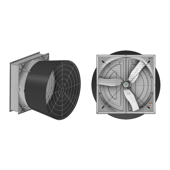
57" Flush Mount Direct Drive Endura
Fan
56911-1
56911-2
56911-3
Operating static pressure should be less than 0.25 inches water column [62 Pa].
The fan inlet and exhaust must be kept clear of obstructions. Failure to keep the fan air-
flow path clear of obstructions could cause loss of fan performance and fan damage.
August 2021
Bess Lab Test*
Phase
21079
1
21080
3
20436
3
*Bess Lab test data available at http://bess.illinois.edu/type.asp
56911-X
Voltage
Hz
230
60
230
60
380
50
®
Fan
Full Speed RPM
630
630
630
MV2494B
Advertisement
Table of Contents

Related Manuals for Chore-Time Endura 56911 Series


Summary of Contents for Chore-Time Endura 56911 Series
- Page 1 ® 57" Flush Mount Direct Drive Endura 56911-X Bess Lab Test* Phase Voltage Full Speed RPM 56911-1 21079 56911-2 21080 56911-3 20436 *Bess Lab test data available at http://bess.illinois.edu/type.asp Operating static pressure should be less than 0.25 inches water column [62 Pa]. The fan inlet and exhaust must be kept clear of obstructions.
-
Page 2: Table Of Contents
Contents Topic Page Safety Information ............. . . 3 DANGER: Electrical Hazard . -
Page 3: Safety Information
(“Extended Warranty Period”) with respect to certain Product parts (“Component Part”) as set forth in the table below. If such a defect is determined by Chore-Time to exist within the applicable period, Chore-Time will, at its option, (a) repair the Product or Component Part free of charge, F.O.B. -
Page 4: Fan Component Part Numbers
Fan Component Part Numbers 57" DD Fan Kit Part Numbers Fan Kit Part Number 56911-1 56911-2 56911-3 56911-1S 56911-2S 56911-3S Phase Voltage 380-480 380-480 Cone Grill Ring Spacing 6" [152mm] 6" [152mm] 6" [152mm] 6" [152mm] 6" [152mm] 6" [152mm] Fan Blade Material Galv. -
Page 5: Tools Needed And Supplies
•Phillips Screwdriver •Drill •3/16" Drill Bit •Expansion Clamp (See “Cone Assembly” on page 12) •3/8" Socket •1/2" Socket or Wrench •Side Cutters •Caulking VFD Cross Reference Part Numbers Chore-Time Part Number Invertek Model Number 56541-1-X ODE-3-120070-101A 56541-2-X ODE-3-120070-301A 56541-3-X ODE-3-140041-301A MV2494B... -
Page 6: Endura Dd Flush Mount Fan New Installation Planning
Endura® DD Flush Mount Fan New Installation Planning 57" Flush Mount Direct Drive Endura® Fan Endura ® DD Flush Mount Fan New Installation Planning Planning the layout of the spacing between Fans is very important. Spacing too close together will cause interference between the discharge Cones. -
Page 7: Spacing
57" Flush Mount Direct Drive Endura® Fan Installation Spacing Planning the layout of the spacing between fans is very important. Spacing too close together will cause interference between the discharge cones. 60-1/16" [152.5cm] Mini- 72" [182.9cm] mum Spacing if Recommended Spacing sides of Cone are 5"... -
Page 8: Assembling The Extension Housing
Assembling the Extension Housing Step 1: Set the panels in the framed opening as shown. One Notch Three Notches Top Panel (56972) Left Side Panel (56971-1) (56971-2) Right Side Panel View from Inside Two Notches the House Four Notches Bottom Panel (56973) - Page 9 57" Flush Mount Direct Drive Endura® Fan Installation Step 2: Use four Self Tapping Screws (54683) to Fasten the Panels together using the holes provided toward the outside of the house as shown. Other four Screws will be installed after squaring. (54683) (54683) 1/4-20 x 1/2"...
- Page 10 Installation 57" Flush Mount Direct Drive Endura® Fan Step 4: Use a Level to level the Side Panels and attach them to the Wall with Screen Clip Washers (56671) and 1/4-10 x 1-1/2" Lag Screws (41561) as shown. Angle Lag Screws away from Fan as shown on the previous page.
- Page 11 57" Flush Mount Direct Drive Endura® Fan Installation Attaching the Fan to the Extension Housing Step 1: Set the Fan on the Bottom Panel Shelf as shown. Eyebolt indicates the top of the Fan Shelf Step 2: Attach the Shroud to the Extension Box Panels with 20x 1/4-20 x 7/8" SS Bolts (4404-17) and 1/4-20 Flange Nuts (46298) as shown.
-
Page 12: Cone Assembly
Installation 57" Flush Mount Direct Drive Endura® Fan Cone Assembly Assemble Cone Panels as shown below. Prop the Cone Panels up off the ground to ease assembly One Hole Two Holes Tabs Up Tabs Snap positively in place MV2494B... -
Page 13: Installing The Orifice Frame
57" Flush Mount Direct Drive Endura® Fan Installation Installing the Orifice Frame Rounded Tab on the Cone Important! Line up the Seam in the Orifice Frame with one of the rounded Tabs on the Cone. Orifice Frame Shown Gray for Clarity. (46764) (53611) Frame... -
Page 14: Cone Installation
Installation 57" Flush Mount Direct Drive Endura® Fan Cone Installation Step 1: Hang the Cone on the Eye-Bolt extruding from the top of the Shroud using the hole in the Cone as shown. (30663) Eyebolt Seam in Orifice Frame Step 2: Attach the Cone to the Shroud with 5/16 Flg. Nuts (46764) as shown If necessary, slip a thin piece of metal between the Shroud... -
Page 15: Re-Install Doors
57" Flush Mount Direct Drive Endura® Fan Installation Re-install Doors Insert Door Pins into Bottom Grab the Door in the center, bow the Door outward, and Pivot Plate. insert the Top Door Pin in the Top Pivot Bracket as shown. Do not Overbow the Doors! Bottom Pivot Plate Top Pivot Plate Door Pin... -
Page 16: Grill Installation
Installation 57" Flush Mount Direct Drive Endura® Fan Grill Installation Install the Fan Cone Grill (as shown). Attach the end of the Door Stop Cable to the bottom Grill Leg as shown. (54287) (46764) (ST99070) Door Stop Cable (46764) (54287) (46764) Door Stop Cable (54287) -
Page 17: Fan Drive (Vfd) Mounting
57" Flush Mount Direct Drive Endura® Fan Installation Fan Drive (VFD) Mounting Select a location next to the Fan to install the Fan Drive. See the Invertek VFD Quick Start Guide (MV2492) that comes with the drive, or online at www.choretime.com/documents, Manuals, Ventilation, Fans & Shutters, 57"... -
Page 18: Screen Installation
Screen Installation Center Screen on the wall opening. Loosen the Lag Screws enough to allow the Screen to be captured by the Screen Clip Washers and Rotate them as shown. Tighten down the Lags to Secure Fan and Screen to the Wall. -
Page 19: Control Signal Wiring
57" Flush Mount Direct Drive Endura® Fan Control Signal Wiring Control Signal Wiring See the Invertek Quick Start Guide that comes packaged with the VFD for VFD wiring instructions. Further information is also available in the Invertek ODE-3 IP66 Outdoor User Guide (MV2493). It can be viewed online at www.choretime.com/documents, Manuals, Ventilation, Fans &... -
Page 20: Test Fan For Proper Operation
Test Fan for proper operation 57" Flush Mount Direct Drive Endura® Fan Test Fan for proper operation Supply power to the VFD and check for proper operation. If the Fan turns in the wrong direction interchange any two wire connections between the drive and the motor to correct the direction of fan blade rotation. Maintenance IMPORTANT! Disconnect Power Prior To Maintaining Or Cleaning The Fan. - Page 21 57" Flush Mount Direct Drive Endura® Fan Maintenance This page left blank intentionally..MV2494B...
-
Page 22: Parts Numbers (Itemized)
Parts Numbers (Itemized) Top Corner Brackets have two Notches Bottom Corner Brackets have one Notch. - Page 23 Item Qty. Description Part No. ® 57" Direct Drive Endura Fan (56911-X,-XS) Part Numbers Motor, 230V, 7A, 630RPM PMSM 56501 -1,-2,-1S,-2S Motor, 380-480V, 4.1A, 630RPM PMSM 56704 -3,-3S 57" Fan Shroud Assembly 52925 57" Cross Rod Coupler 56339 Rivet 48936 57"...
-
Page 24: Part Numbers (Itemized) Continued
Part Numbers (Itemized) continued Used when Spacing Fans close together... - Page 25 Item Qty. Description Part No. 57" DD Endura® Fan (56911-X, -XS, -XT) Part Numbers 57" Left Hand Fan Door 52926L 57" Right Hand Fan Door 52926R 11** Magnet Striker Plate 53027 57" Fan Orifice Frame 53416 57" Fan Top Pivot Plate 53037 57"...
- Page 26 Description of Change Added Bess Lab Test Results 35514 Changed 54530 to 57022 Blade For additional parts and information, contact your nearest Chore-Time distributor or representative. Find your nearest distributor at: www.choretime.com/contacts CTB, Inc. PO Box 2000 Milford, Indiana 46542-2000 USA Phone (574) 658-4101 Fax (877) 730-8825 Email: choretime@choretime.com...
Need help?
Do you have a question about the Endura 56911 Series and is the answer not in the manual?
Questions and answers