Table of Contents
Advertisement
Quick Links
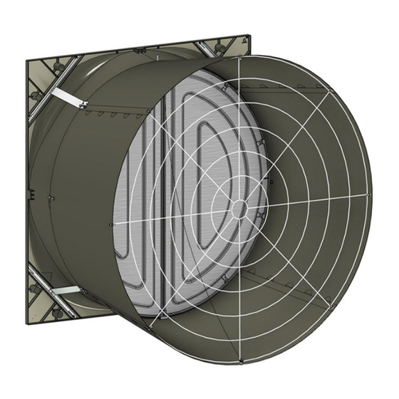
57" Assembled & Unassembled
Direct Drive EnduraMax™ Fan
2491-001 07/20
2491-002 07/20
Fan Part No. 57611-11
Fan
Bess Lab Test*
Phase
Voltage
Hz
Full Speed RPM
57611-11
24694
1
220-240
60
630
*Bess Lab test data available at http://bess.illinois.edu/type.asp
Operating static pressure should be less than 0.25 inches water column [62 Pa].
The Fan Inlet and exhaust must be kept clear of obstructions. Failure to keep the Fan airflow path clear of
obstructions could cause loss of Fan performance and Fan damage.
December 2024
MV2521A
Advertisement
Table of Contents

Related Manuals for Chore-Time EnduraMax 57611-11


Summary of Contents for Chore-Time EnduraMax 57611-11
- Page 1 57" Assembled & Unassembled Direct Drive EnduraMax™ Fan 2491-001 07/20 2491-002 07/20 Fan Part No. 57611-11 Bess Lab Test* Phase Voltage Full Speed RPM 57611-11 24694 220-240 *Bess Lab test data available at http://bess.illinois.edu/type.asp Operating static pressure should be less than 0.25 inches water column [62 Pa]. The Fan Inlet and exhaust must be kept clear of obstructions.
-
Page 2: Table Of Contents
Contents Topic Page Safety ................3 Warning . -
Page 3: Safety
57" Assembled & Unassembled Direct Drive EnduraMax™ Fan Safety Safety Warning This product has inherent dangers, which can cause damage or loss to persons or equipment if the warnings in this manual are not adhered to. Please read and follow all instructions. Personnel Requirements This product must only be used by persons adequately trained in the hazards, dangers, and risks of the equipment. -
Page 4: Residual Risks
Safety 57" Assembled & Unassembled Direct Drive EnduraMax™ Fan Residual Risks Despite the level of caution taken and the incorporation of safeguards, some risks will remain. This product has the following hazards: Hazard Safeguard Operator Requirement Cutting or trapping Fixed guards Maintain all fixed guards in proper location and good Ejection of parts... -
Page 5: Limited Warranty
Chore-Time Group, a division of CTB, Inc. (“Chore-Time”) warrants new CHORE-TIME EnduraMax™ Fans manufactured by Chore-Time to be free from defects in material or workmanship under normal usage and conditions, for One (1) year from the date of installation by the original purchaser (“Warranty”). Chore-Time provides for an extension of the aforementioned Warranty period (“Extended Warranty Period”) with respect to certain Product parts (“Component Part”) as set forth in the table below. -
Page 6: Unassembled Fan Component Part Numbers
Unassembled Fan Component Part Numbers Fan Blade Part No. (on Blade Spider) Unassembled 57" DD Fan Kit Part Numbers Fan Kit Part Number 57611-11U Phase Voltage 220-240 Cone Grill Spacing 6" [152mm] Fan Blade Material Galv. Item Description Component Part No. 57"... -
Page 7: Assembled Fan Component Part Numbers
Assembled Fan Component Part Numbers Assembled 57" DD Fan Kit Part Numbers Fan Kit Part Number 57611-11 Phase Voltage 220-240 Cone Grill Ring Spacing 6" [152mm] Fan Blade Material Galv. Item Description Component Part No. 57" DD Fan Sub-Assembly 57611-11P 57"... -
Page 8: Tools Needed And Supplies
3/16" Drill Bit • Expansion Clamp (See “Keeping Fan Shroud edges straight” on page 15) • 3/8" Socket • 1/2" Socket or Wrench • Side Cutters • Caulking VFD Cross Reference Part Numbers Chore-Time Part Number Keld Model Number 58142-1 KMD2-0C00GAG MV2521A... -
Page 9: Enduramax™ Dd Fan New Installation Planning
57" Assembled & Unassembled Direct Drive EnduraMax™ Fan EnduraMax™ DD Fan New Installation Planning EnduraMax DD Fan New Installation Planning ™ Planning the layout of the spacing between Fans is very important. Spacing too close together will cause interference between the discharge Cones. See “Fan Drive (VFD) Mounting” on page 22. !Important: Provide Shelter over Cones in areas where snow or ice could cause damage. -
Page 10: Installation
Installation 57" Assembled & Unassembled Direct Drive EnduraMax™ Fan Installation Inspecting the Shroud Inspect the Shroud assembly for hardware as received. (53626) Center V-Post (48427) Magnet (53026) Magnet Side Plate Assembly Jig for Unassembled Fans (For assembled versions skip to page 12) For ease of Fan assembly it is helpful to create an elevated flat surface as shown. -
Page 11: Install Motor Supports
57" Assembled & Unassembled Direct Drive EnduraMax™ Fan Installation Install Motor Supports Important! Direction of Bolts Support right of Top Tab Support Left of Bottom Orient Motor Supports as shown. Item Description Part No. 57" DD Fan Motor Support 57592 5/16-18 x 1 Bolt 54287 (46764) 5/16 Flg. -
Page 12: Shroud And Shroud Components Installation
Installation 57" Assembled & Unassembled Direct Drive EnduraMax™ Fan Shroud and Shroud Components Installation 1.Assemble the four corner Bracket assemblies by threading (4412-28) Bolts into the Corner Supports as shown. Each Corner Bracket Assembly is unique. Make sure to use the appropriate Corner Support with the Bolt in the correct hole as shown. - Page 13 57" Assembled & Unassembled Direct Drive EnduraMax™ Fan Installation 2.Fasten the Cone Supports and Brackets to the Fan Motor Supports with 4 (46764) Nuts as shown. Item Description Part No. 5/16 Flg. Nut 46764 (46764) 5/16 Flg. Nut 3.Install the Top Pivot Plate Bracket (53037), Bottom Pivot Plate Bracket (53036), Fan Cone Cable (50618-5) and Eye-Bolt (30663) as shown.
-
Page 14: Bottom Shelf Installation
Installation 57" Assembled & Unassembled Direct Drive EnduraMax™ Fan Bottom Shelf Installation Center of Rough Opening Tighten until Snug only. Do not Deform the Bottom Shelf.) (53338) Bottom Shelf Outside of House Center of Bottom Shelf If the Shelf is too long Trim equal amounts from both ends. -
Page 15: Keeping Fan Shroud Edges Straight
57" Assembled & Unassembled Direct Drive EnduraMax™ Fan Installation Keeping Fan Shroud edges straight It is important when attaching the Fan to the Wall to keep edges of Shroud straight. A 600 Lb. Hand Clamp can be used to straighten Shroud if necessary. Keep edges of Shroud Straight Note: Shown without Doors and Blade for Clarity. -
Page 16: Cone Assembly
Installation 57" Assembled & Unassembled Direct Drive EnduraMax™ Fan Cone Assembly Assemble Cone Panels as shown below. Prop the Cone Panels up off the ground to ease assembly One Hole Two Holes Tabs Up Tabs Snap positively in place MV2521A... -
Page 17: Installing The Orifice Frame
57" Assembled & Unassembled Direct Drive EnduraMax™ Fan Installation Installing the Orifice Frame Rounded Tab on the Cone Important! Line up the Seam in the Orifice Frame with one of the rounded Tabs on the Cone. Orifice Frame Shown Gray for Clarity. (46764) (53611) Frame... - Page 18 Installation 57" Assembled & Unassembled Direct Drive EnduraMax™ Fan Attach the cone to the Shroud as shown below. Slip the Orifice Frame behind the Bottom Pivot Plate. Bottom Pivot Plate 5/16 Flg. Nut (46764) If necessary, slip a thin piece of metal between the Shroud and Cone and work it around the Cone to get it on.
-
Page 19: Door Assembly And Installation
57" Assembled & Unassembled Direct Drive EnduraMax™ Fan Installation Door Assembly and Installation Doors are Left and Right specific. Insert Door Pins in both Doors as shown. Push Pins in until they bottom out. (53038) Door Pin View of Back of Door View of Back of Door Door Spring... -
Page 20: Grill Installation
Installation 57" Assembled & Unassembled Direct Drive EnduraMax™ Fan Grill Installation Install the Fan Cone Grill (as shown). Attach the end of the Door Stop Cable to the bottom Grill Leg as shown. (54287) Door Stop Cable (46764) (54287) (46764) Door Stop Cable even with the (54287) -
Page 21: Check Blade Tip Clearance
57" Assembled & Unassembled Direct Drive EnduraMax™ Fan Installation Check Blade Tip Clearance Push only on inner most 2" [5.08 cm] of Shroud If Clearance is insufficient, check that the mounting surface is flat, and that the sides of 1/8" [3mm] the Shroud are straight. -
Page 22: Caulking
Installation 57" Assembled & Unassembled Direct Drive EnduraMax™ Fan Caulking Caulk both Ends of the Bottom Shelf to fill any gaps between the Shroud and the Framed opening. Caulk Both Ends of the Bottom Shelf Fan Drive (VFD) Mounting Select a location next to the Fan in the Fan air stream for VFD cooling a maximum of 12" [30.5cm] away from the Fan opening. -
Page 23: Screen Installation
57" Assembled & Unassembled Direct Drive EnduraMax™ Fan Installation Screen Installation Center Screen on the wall opening and (41561) Lag Screw angled fasten with 8 Screen Clip Washers slightly outward will allow (56671) and (41561) Lag Screws as for easier Screen removal 3/8"... -
Page 24: Control Signal Wiring
Control Signal Wiring 57" Assembled & Unassembled Direct Drive EnduraMax™ Fan Control Signal Wiring For variable speed Fan control, connect the 0-10 vdc analog signal from the Main Control to VFD analog input (AI) and ground (GND). The fan will run full speed with an analog signal of 10 vdc and slow down to a minimum speed of 200 rpm at 3.2 volts, stopping at any voltage less than 3.2 V. -
Page 25: Test Fan For Proper Operation
57" Assembled & Unassembled Direct Drive EnduraMax™ Fan Test Fan for proper operation Test Fan for proper operation Supply power to the VFD and check for proper operation. If the Fan turns in the wrong direction interchange any two wire connections between the drive and the motor to correct the direction of fan blade rotation. Maintenance IMPORTANT! Disconnect Power Prior To Maintaining Or Cleaning The Fan. -
Page 26: Parts Numbers (Itemized)
Parts Numbers (Itemized) Top Corner Brackets have two Notches Bottom Corner Brackets have one Notch. - Page 27 Item Qty. Description Part No. Motor, Direct Drive 3 HP, 220-240V, 630 RPM 57401 57" Fan Shroud Assembly 52925 57" Cross Rod Coupler 56339 Rivet 48936 57" Fan Center Post Stiffner 53626 57" Fan Cross Rod 53398 Magnet Side Plate 53026 .125 x .50 Magnet 48427...
-
Page 28: Part Numbers (Itemized) Continued
Part Numbers (Itemized) continued Used when Spacing Fans close together... - Page 29 Item Qty. Description Part No. 57" Left Hand Fan Door 52926L 57" Right Hand Fan Door 52926R 11** Magnet Striker Plate 53027 57" Fan Orifice Frame 53416 57" Fan Top Pivot Plate 53037 57" Bottom Pivot Plate 53036 .50 OD x 11 x .055 SS Spring 49629 72"...
-
Page 30: Revisions To This Manual
Revisions to this Manual Page No. Description of Change New Manual 40493 For additional parts and information, contact your nearest Chore-Time distributor or representative. Find your nearest distributor at: www.choretime.com/contacts CTB, Inc. PO Box 2000 Milford, Indiana 46542-2000 USA Phone (574) 658-4101 Fax (877) 730-8825 Email: choretime@choretime.com...
Need help?
Do you have a question about the EnduraMax 57611-11 and is the answer not in the manual?
Questions and answers