Contec IPC Series User Manual
Silicon disk drive with raid
for pci
Hide thumbs
Also See for IPC Series:
- User manual (107 pages) ,
- Operational manual (87 pages) ,
- Manual (75 pages)

Subscribe to Our Youtube Channel
Related Manuals for Contec IPC Series


Summary of Contents for Contec IPC Series
- Page 1 IPC Series Silicon Disk Drive with RAID for PCI 1GB type PC-RSD1000-PCI 2GB type PC-RSD2000-PCI 4GB type PC-RSD4000-PCI 8GB type PC-RSD8000-PCI CF uninstalling type PC-RSD-PCI User’s Manual CONTEC CO.,LTD.
- Page 2 Check Your Package Thank you for purchasing the CONTEC product. The product consists of the items listed below. Check, with the following list, that your package is complete. If you discover damaged or missing items, contact your retailer. Product Configuration List Product [One of the followings] …1...
-
Page 3: Copyright
No part of this document may be copied or reproduced in any form by any means without prior written consent of CONTEC CO., LTD. CONTEC CO., LTD. makes no commitment to update or keep current the information contained in this document. The information in this document is subject to change without notice. -
Page 4: Table Of Contents
Table of Contents Check Your Package ..........................i Copyright ..............................ii Trademarks ..............................ii Table of Contents ...........................iii BEFORE USING THE PRODUCT About the Board ............................1 Features............................. 1 Accessories (Option)........................1 Customer Support............................ 2 Web Site ............................2 Limited One Year Warranty ........................2 How to Obtain Service.......................... - Page 5 Installing Windows 2000 newly on a hard disk or this product ............19 Installing drivers while installing Windows 2000 newly..............19 Check Method of Hardware Install Completion ................20 Setup Troubleshooting...........................21 Symptoms and Actions........................21 If your problem cannot be resolved ....................21 FUNCTION IDE Function............................23 RAID Function ............................23 RAID 0 (Striping)...........................23 RAID 1 (Mirroring)........................23...
-
Page 6: Before Using The Product
1. Before Using the Product 1. Before Using the Product This chapter provides information you should know before using the product. About the Board This product is a PCI board type silicon disk drive. It can be used the same as a hard disk by mounting it to a PCI bus slot of your PC. -
Page 7: Customer Support
You can download updated driver software and differential files as well as sample programs available in several languages. Note! For product information Contact your retailer if you have any technical question about a CONTEC product or need its price, delivery time, or estimate information. Limited One Year Warranty CONTEC products are warranted by CONTEC CO., Ltd. -
Page 8: Safety Precautions
Even when using the product continuously, be sure to read the manual and understand the contents. All relevant issues have been considered in the preparation of this document. Should you notice an omission or any questionable item in this document, please feel free to notify CONTEC CO., LTD. PC-RSD Series... - Page 9 1. Before Using the Product Do not modify the product. CONTEC will bear no responsibility for any problems, etc., resulting from modifying this product. Regardless of the foregoing statements, CONTEC is not liable for any damages whatsoever (including damages for loss of business profits) arising out of the use or inability to use this CONTEC product or the information contained herein.
-
Page 10: Environment
1. Before Using the Product Environment Use this product in the following environment. If used in an unauthorized environment, the board may overheat, malfunction, or cause a failure. Operating temperature 0 - 50°C Operating humidity 10 - 90%RH (No condensation) Corrosive gases None Floating dust particles... - Page 11 1. Before Using the Product PC-RSD Series...
-
Page 12: Setup
2. Setup 2. Setup This chapter explains how to set up the board. What is Setup? Setup means a series of steps to take before the product can be used. Different steps are required for software and hardware. The setup procedure varies with the OS and applications used. Follow the steps shown in this chapter to prepare hardware and software. -
Page 13: Step 1 Setting The Hardware
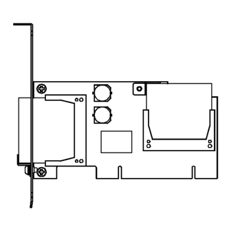
2. Setup Step 1 Setting the Hardware This section describes how to set the board and plug it on your PC. Remove CFs in advance before Windows is newly installed on the hard disk or before this product is added to your PC on which Windows is currently installed. Parts of the Board Figure 2.1. - Page 14 2. Setup (7) Attach the board bracket to the PC with a screw. (8) If OS is DOS or a new OS is installed to the CF of this product, check if the CF is mounted on this product and then put the cover back into place. If Windows is newly installed to a hard disk or this product is added to the PC on which Windows is currently installed, proceed to “Step 2 Installing the Hardware”, mount the CF on the slot where it was originally mounted on and then put the cover back into place.
-
Page 15: Step 2 Installing The Hardware
2. Setup Step 2 Installing the Hardware Windows needs to detect the I/O address and interrupt used by the board. This is called hardware installation. The procedure is different for each OS. Install the hardware according to the respective procedure. After the hardware installation is completed, the hardware can be used as a disk drive on Windows. - Page 16 2. Setup (2) The “Found New Hardware Wizard” will be started. Select “Install from a list or specific location[Advanced]”, then click on the [Next] button. (1) Select (2) Click (3) Select “Search for the best driver in these locations.” and then check only the (1) Select “Include this location in the search:”.
-
Page 17: Check Method Of Hardware Install Completion
2. Setup (7) If the “System Settings Changes”is displayed, click the [No] button. Click CAUTION In Windows XP, the Hardware Wizard displays the following alert dialog box when you have located the INF file. This dialog box appears, only indicating that the relevant driver has not passed Windows Logo testing, and it can be ignored without developing any problem with the operation of the board. -
Page 18: Installing Windows Xp Newly On A Hard Disk Or This Product
After [Windows XP setup] is displayed, press [S] key to specify a driver you want to add. Insert the supplied Driver FD into the floppy drive and press [Enter] key. Select “CONTEC PC-RSD Series (Windows XP)” from a list displayed on the screen and press [Enter] key. -
Page 19: Check Method Of Hardware Install Completion
2. Setup CAUTION In Windows XP, the Hardware Wizard displays the following alert dialog box of [Installng Software], [Installing Hardware]. This dialog box appears, only indicating that the relevant driver has not passed Windows Logo testing, and it can be ignored without developing any problem with the operation of the board. -
Page 20: Mounting This Product On Windows 2000 Installed Pc
2. Setup Mounting this product on Windows 2000 installed PC Turning on the PC After mounting the board in “Step 1 Setting the Hardware ” and checking if the CF has been removed, turn on your PC. A message saying “IT8212 RAID... ” will be displayed after a period of time. At this time, RAID setting is not performed, so press [Esc] key. - Page 21 2. Setup (3) Select only the “Specify a location” and then click the [Next] button. (1) Specify (2) Click (2) Click (4) Insert the supplied Driver FD into the floppy drive, spcify the following source folder and then click [OK] button. - Source folder A:\WIN2K (1) Specify (5) This product is found.
- Page 22 2. Setup (7) Click the [Finish] button. Click (8) If the “System Setting Change” is displayed, click the [No] button. Click CAUTION In Windows 2000, the Hardware Wizard displays the following alert dialog box when you have located the INF file. This dialog box appears, only indicating that the relevant driver has not passed Windows Logo testing, and it can be ignored without developing any problem with the operation of the board.
-
Page 23: Check Method Of Hardware Install Completion
2. Setup Check Method of Hardware Install Completion (1) Click the [Start] button on the left side of task bar and then double click the [System] from the [Setting]→[Control Panel]. (2) When the [System propaties] is displayed, click the [Hardware] tab and then click the [Device Manager]. (3) Check if the board name has been registered correctly in [SCSI and RAID controllers]. -
Page 24: Pc-Rsd Series
After [Windows 2000 setup] is displayed, press [S] key to specify a driver you want to add. Insert the supplied Driver FD into the floppy drive and press [Enter] key. Select “CONTEC PC-RSD Series (Windows 2000)” from a list displayed on the screen and press [Enter] key. -
Page 25: Check Method Of Hardware Install Completion
2. Setup Press [Enter] key on [Windows 2000 setup] screen to continue the Windows 2000 installation. In the middle of installation, the Windows 2000 installation location can be selected from either the CF of this product or PC hard disk. The message “Cannot find digital signature” appears in the next window. -
Page 26: Setup Troubleshooting
2. Setup Setup Troubleshooting Symptoms and Actions PC does not start up after this product has been mounted. This product does not work. ”!” mark is shown in [Device manager]. Make sure that this product is attached correctly. Check if there is any shortage of resources allocatable to this product. When using a board not compliant with Plug and Play, change the resource allocation for the board. - Page 27 2. Setup PC-RSD Series...
-
Page 28: Function
3. Function 3. Function This chapter explains the function equipped with the board. IDE Function The CFs mounted on this product can be used as normal IDE disk drives. They are connected as two drives on the installed RAID controller. The internal CF is connected as the primary master and the external CF (blanket side) is connected as the secondary master. - Page 29 3. Function PC-RSD Series...
-
Page 30: About The Raid Building Software
4. About the RAID Building Software 4. About the RAID Building Software To build RAID, a new CF should be mounted on the add-on CF slot of this product. After mounting an additional CF, RAID can be built using utilities. For RAID configuring utilities, “Setup Utility”... - Page 31 4. About the RAID Building Software (3) The following screen is displayed. First, check to see if CFs are connected correctly. Press [5] key to start [RAID Card Configuration]. IT8212 Setup Utility (C) Copyright 2002 - 2004 ITE, Inc. [Main Menu] Auto Configuration………………….[1] Define RAID………………………...[2] Delete RAID………………………...[3]...
-
Page 32: Building A Striping (Raid 0)
4. About the RAID Building Software Building a striping (RAID 0) (1) After starting Setup Utility, press [2] key in [Setup Utility] main menu. Auto Configuration………………….[1] Define RAID………………………...[2] Press [2] and start up the Delete RAID………………………...[3] [Define RAID]. Rebuild RAID……………………….[4] RAID Card Configuration…………..[5] (2) On [Define RAID Menu] screen, select an unset [Array No] using [↑][↓] keys and then press [Enter] key. - Page 33 4. About the RAID Building Software (3) Set each setting item. Move to another item using [↑][↓] keys. The value can be changed for each item using [Space] key. Setting item Setting value Array Mode Stripe Block Size Set the dividing size for data. The performance will be improved by using the optimum value.
- Page 34 4. About the RAID Building Software (4) Press [Y] key to set striping. The data of the selected CF will be erased upon selecting striping for the CF by pressing [Y] key and the data cannot be restored. Erase old data in this new array? Y - Yes / N - No CAUTION The data of the CF will be erased upon pressing [Y] key and the data cannot be restored.
-
Page 35: Building A New Mirroring (Raid 1) Using Two Cfs
4. About the RAID Building Software Building a new mirroring (RAID 1) using two CFs (1) After starting Setup Utility, press [2] key in [Setup Utility] main menu. Auto Configuration………………….[1] Press [2] and start up the Define RAID………………………...[2] Delete RAID………………………...[3] [Define RAID]. - Page 36 4. About the RAID Building Software (3) Setup the following setting items. You can move to each item with the [↑][↓] key, and change each setting value with the [Space] key. Setting item Setting value Array Mode Mirror Change the setting Drive Assignment [Y] : Mirroring is set for each item...
- Page 37 4. About the RAID Building Software (6) After checking that the mirroring has been set, press [Esc] key. [Define RAID Menu] Array No. Array Mode Drive No. Size(MB) Status Array 0 Mirror Functional Press [Esc] key in [Setup Utility] main menu. Auto Configuration………………….[1] Define RAID………………………...[2] Delete RAID………………………...[3]...
-
Page 38: Setting The Cf Which Has Already Been Used And Added To Mirroring (Raid 1)
4. About the RAID Building Software Setting the CF which has already been used and added to mirroring (RAID 1) (1) After starting Setup Utility, press [2] key in [Setup Utility] main menu. Auto Configuration………………….[1] Define RAID………………………...[2] Press [2] and start up the Delete RAID………………………...[3] [Define RAID]. - Page 39 4. About the RAID Building Software (3) Setup the following setting items. You can move to each item with the [↑][↓] key, and change each setting value with the 'Space' key. Setting item Setting value Array Mode Mirror Drive Assignment [Y] : Mirroring is set Change the setting [N] : Mirroring is not set...
- Page 40 4. About the RAID Building Software The following screen appears. Do you like to rebuild current array? Y - Yes / N - No Press the [Y] key, and the mirroring will be reconfigured and the screen (6) is displayed. When [N] key is pressed by mistake, a screen for selecting a copy source is displayed.
- Page 41 4. About the RAID Building Software (9) When [Y] is pressed in (8), the copy status is displayed. The following completion message screen will be displayed when the copy status reaches to [100%], then press any key. When [N] is pressed in (8), neither the copy status nor a completion message will be displayed. When copying is started, LED of this product lights up.
-
Page 42: Building A Spanning
4. About the RAID Building Software Building a Spanning (1) After starting Setup Utility, press [2] key in [Setup Utility] main menu. Auto Configuration………………….[1] Press [2] and start up the Define RAID………………………...[2] [Define RAID]. Delete RAID………………………...[3] Rebuild RAID……………………….[4] RAID Card Configuration…………..[5] (2) On Define RAID Menu screen, select Array No that is not set with the [↑][↓] key, and then press [Enter]. - Page 43 4. About the RAID Building Software (3) Setup the following setting items. You can move to each item with the [↑][↓] key, and change each setting value with the [Space] key. Once you have changed these settings, press [Ctrl-Y] (while hoiding down [Ctrl], press the [Y] key).
- Page 44 4. About the RAID Building Software (6) After checking that the spanning has been set, press [Esc] key. [Define RAID Menu] Array No. Array Mode Drive No. Size(MB) Status Array 0 Span 1954 Functional (7) Press [Esc] key in [Setup Utility] main menu. Auto Configuration………………….[1] Define RAID………………………...[2] Delete RAID………………………...[3]...
-
Page 45: Canceling Raid Setting
4. About the RAID Building Software Canceling RAID Setting (1) After starting Setup Utility, press [3] key in [Setup Utility] main menu. Auto Configuration………………….[1] Define RAID………………………...[2] Delete RAID………………………...[3] Press [3] and start up the Rebuild RAID……………………….[4] [Delete RAID]. RAID Card Configuration…………..[5] (2) On [Delete RAID Menu] screen, select an [Array No] to be cancelled using [↑][↓] keys and then press [D] key. -
Page 46: Raidmgr Utility
“Setup Utility” to build RAID. “RaidMgr” is installed after installing this product, the board name may be changed in some cases. Installing RaidMgr Utility (1) Download the support software [ITERAID.exe] from CONTEC web site. (2) Copy it to the PC on which you want to mount this product. (3) Execute [ITERAID.exe]. -
Page 47: Starting Raidmgr
4. About the RAID Building Software Starting RaidMgr (1) Start your PC after mounting the CF on this product. (2) “ ” icon of the [RaidMgr] registered when installing the support software appears in the task tray at the lower right corner of the desktop screen. Right-click on the icon and click [Open] on a displayed menu. -
Page 48: Building A Striping (Raid 0)
4. About the RAID Building Software Building a striping (RAID 0) CAUTION Upon setting striping, the data inside CFs are deleted and cannot be restored. (1) Click the menu on the lower left of RaidMgr screen and click [Create Disk Array]. (2) After selecting a CF for building striping, click “... - Page 49 4. About the RAID Building Software (3) Select the [RAID 0] in the [Array Type]. (4) Select the [Stripe Size]. (Initial value : 64KB) [Stripe Size] is used to set the size for dividing data. The performance will be improved by using the optimum value.
-
Page 50: Building A Mirroring (Raid 1)
4. About the RAID Building Software Building a mirroring (RAID 1) CAUTION Upon setting the mirroring, the data inside CFs are deleted and cannot be restored. (1) Click a part of the menu displayed in the lower left of the RaidMgr screen, and then click [Create Disk Array]. - Page 51 4. About the RAID Building Software (3) Select the [RAID 1] in the [Array Type]. (4) Click “ ” button at the bottom of the screen to build mirroring. CAUTION Upon pressing [Create] button, the data inside CFs are deleted and cannot be restored. (5) When the screen asking you whether to reboot is displayed, click [OK] to reboot your PC.
-
Page 52: Building A Spanning (Jbod)
4. About the RAID Building Software Building a spanning (JBOD) CAUTION Upon setting the spanning, the data inside CFs are deleted and cannot be restored. (1) Click a part of the menu displayed in the lower left of the RaidMgr screen, and then click Create Disk Array. - Page 53 4. About the RAID Building Software (3) Select the [JBOD] in the [Array Type]. (4) Click “ ” button at the bottom of the screen to build spanning. CAUTION Upon pressing [Create] button, the data inside CFs are deleted and cannot be restored. (5) When the screen asking you whether to reboot is displayed, click [OK] to reboot your PC.
-
Page 54: Screen Details On Raidmgr
4. About the RAID Building Software Screen details on RaidMgr Settings / display area Refresh Close RaidMgr. System Information : Showing the RAID information and the information of connected CFs. Configuration : Executing the RAID settings. Create Disk Array (Create the RAID settings) : Building the RAID. -
Page 55: Delete The Built Raid
4. About the RAID Building Software Delete the built RAID Moving the selected disk Available disks Selected disks (Disks with RAID (Disks for deleting setting) RAID setting) Check if you The information of the available disks and selected want to erase disks are displayed. -
Page 56: Rebuilding A Mirror Disk
4. About the RAID Building Software Rebuilding a mirror disk Check if you want to restart from the previous process when the rebuilding is suspended before completing. Set the status update time The information of rebuilding target, copy source and copy destination disk are displayed. -
Page 57: If Failing A Cf In Mirroring
4. About the RAID Building Software If failing a CF in mirroring If a CF used in mirroring is failed, check the following message and follow the procedure below. CF failure check The following error message may be appeared on BIOS screen of this product while mirroring is being used. - Page 58 4. About the RAID Building Software (1) Press any key except [Y] key on the error message screen. (2) Check [Array No] field of [Drive Status] information on [RAID Card Configuration] screen in [Setup Utility] of this product. - If CF is normal: [Array x] (Array No is shown for x) will be displayed.
- Page 59 4. About the RAID Building Software (4) The following message is displayed. Press any key to start rebuilding RAID automatically. Warning!! Array reconstruction has not be completed yet, please enter setup Utillity to rebuild array. Drive x in Array x data is inconsistent, please press ANY KEY to start rebuilding.
-
Page 60: Uninstalling The Support Software And Driver
4. About the RAID Building Software Uninstalling the support software and driver To uninstall the installed support software and drivers, follow the procedure below. About the uninstalling function This function is used to delete the driver and registry information for this product from [Addition and deletion of programs] or [Addition and deletion of applications]. -
Page 61: Uninstalling The Driver
4. About the RAID Building Software Uninstalling the driver (1) Start [Device manager] from [Control panel] - [System]. (2) Delete [CONTEC PC-RSD Series] (mounted hardware name) shown in [SCSI and RAID controller]. CAUTION When this product is being used for OS startup, once the installed support software is deleted, this product becomes disabled. -
Page 62: Contents Of Fd
4. About the RAID Building Software Contents of FD This guide (LYFL45_060623.pdf: English), Install setup file |– WINXP Device driver and INF file for Windows XP |– WIN2K Device driver and INF file for Windows 2000 PC-RSD Series... - Page 63 4. About the RAID Building Software PC-RSD Series...
-
Page 64: About Hardware
5. About Hardware 5. About Hardware This chapter provides hardware specifications and hardware-related supplementary information. Hardware specification Table 5.1. Specification PC-RSD-PCI PC-RSD1000-PCI PC-RSD2000-PCI PC-RSD4000-PCI PC-RSD8000-PCI Item RAID controller ITE IT8212F, RAID 0/1/JBOD CF slot Card Slot: Type I x 2 (Internal slot : Primary Master, External slot : Secondary Master) Display : Card access LED (Red) x 1 Uncapable of detaching when enagized Power supply +3.3VDC... -
Page 65: About Rewrite Life
5. About Hardware Board Dimensions 119.91 [mm] The external dimension for (L) [119.91] is the length from the board edge to the exterior surface of the slot cover. About Rewrite Life The number of rewriting a CF is limited due to characteristics of the memory used in the CF. The rewrite life can be calculated as a reference value according to the formula given below. - Page 66 3-9-31, Himesato, Nishiyodogawa-ku, Osaka 555-0025, Japan Japanese http://www.contec.co.jp/ English http://www.contec.com/ Chinese http://www.contec.com.cn/ No part of this document may be copied or reproduced in any form by any means without prior written consent of CONTEC CO., LTD. [06232006] [03022006] Management No. A-51-095 [06232006_rev3] Parts No. LYFK321...
Need help?
Do you have a question about the IPC Series and is the answer not in the manual?
Questions and answers