Contec IPC SERIES User Manual
Box-pc 1000 series
fanless, celeron 927ue 1.50ghz /
core i7-3517ue 1.70ghz
Hide thumbs
Also See for IPC SERIES:
- User manual (99 pages) ,
- Operational manual (87 pages) ,
- Manual (75 pages)
Table of Contents
Advertisement
Quick Links
See also:
Manual
Advertisement
Table of Contents

Related Manuals for Contec IPC SERIES


Summary of Contents for Contec IPC SERIES
- Page 1 IPC Series BOX-PC 1000 Series Fanless, Celeron 927UE 1.50GHz / Core i7-3517UE 1.70GHz User’s Manual CONTEC CO., LTD.
- Page 2 Check Your Package Thank you for purchasing the CONTEC product. The product consists of the items listed below. Check, with the following list, that your package is complete. If you discover damaged or missing items, contact your retailer. Product Configuration List...
-
Page 3: Copyright
No part of this document may be copied or reproduced in any form by any means without prior written consent of CONTEC CO., LTD. CONTEC CO., LTD. makes no commitment to update or keep current the information contained in this document. -
Page 4: Table Of Contents
Table of Contents Check your package ............................. i Copyright ..............................ii Trademarks ..............................ii Table of Contents ............................iii INTRODUCTION About the Product............................1 Features ..............................4 Supported OS ............................5 Customer Support ............................6 Web Site..............................6 Limited One-Year Warranty ........................6 How to Obtain Service .......................... - Page 5 Using Setup ..............................36 Getting Help ............................36 In Case of Problems ........................... 36 A Final Note About Setup ......................... 36 Main Menu ..............................37 Setup Items ............................37 Main................................38 Advanced ..............................39 PCI Subsystem Settings ........................40 ACPI Settings ............................. 41 CPU Configuration ..........................
- Page 6 Line out Interface : LINE OUT ......................71 MIC input Interface : MIC ........................ 71 Serial-ATA : SATA 1, SATA 2 ....................... 72 CFast Connector : CFast........................73 Giga bit-Ethernet : LAN A, LAN B ....................74 USB 3.0 Ports : USB 3.0 ........................75 USB 2.0 ports : USB 2.0 ........................
- Page 7 BX-1000 User’s Manual...
-
Page 8: Introduction
OS for the general-purpose PC. Embedded-type CPU and chip set have been adopted. The use of readily available parts ensures the ease of the use of the product. In addition, the use of CONTEC-customized BIOS allows support to be provided at the BIOS level. - Page 9 1. Introduction Table 1.1. Product Lineup < 1 / 2 > Expansion slot Model Storage device BX-1000-AC37000 BX-1000-AC37315 Windows Embedded CFast 8GB Standard 2009 32bit BX-1000-AC37312 Windows Embedded Standard 7 32bit Japanese BX-1000-AC37316 Windows Embedded CFast 16GB Standard 7 32bit English BX-1000-AC37319 Windows Embedded Standard 2009 32bit...
- Page 10 1. Introduction Table 1.1. Product Lineup < 2 / 2 > Expansion slot Model Storage device BX-1000-AC17000 BX-1000-AC17315 Windows Embedded CFast 8GB Standard 2009 32bit BX-1000-AC17312 Windows Embedded CFast 16GB Standard 7 32bit Japanese BX-1000-AC17316 Windows Embedded Standard 7 32bit English BX-1000-AC17319 Windows Embedded Standard 2009 32bit...
-
Page 11: Features
1. Introduction Features Adoption of ultra-low voltage processor Core i7-3517UE (1.70GHz) or Celeron 927UE (1.50GHz), QM77 chip set, and 4GB of memory These products has the power-saving high-performance, ultra-low-voltage processor Core i7-3517UE (1.70GHz) or Celeron 927UE (1.50GHz), QM77 chip set, and 4GB DDR3 SDRAM memory, achieve a high-level computing and drawing ability. -
Page 12: Supported Os
1. Introduction Supported OS Windows Embedded Standard 2009 32bit Japanese / English Windows Embedded Standard 7 32bit Japanese Windows Embedded Standard 7 32bit English Windows 7 Professional 32bit Japanese Windows 7 Professional 32bit English BX-1000 User’s Manual... -
Page 13: Customer Support
You can download updated driver software and differential files as well as sample programs available in several languages. Note! For product information Contact your retailer if you have any technical question about a CONTEC product or need its price, delivery time, or estimate information. Limited One-Year Warranty CONTEC products are warranted by CONTEC CO., LTD. -
Page 14: Safety Precautions
1. Introduction Safety Precautions Understand the following definitions and precautions to use the product safely. Safety Information This document provides safety information using the following symbols to prevent accidents resulting in injury or death and the destruction of equipment and resources. Understand the meanings of these labels to operate the equipment safely. - Page 15 Avoid installation in a location where people may come into contact with that section. CONTEC does not provide any guarantee for the integrity of data on storage device. Always disconnect the power cable from the receptacle before mounting or removing the expansion board, or before connecting or disconnecting any connector.
- Page 16 1. Introduction FCC PART 15 Class A Notice NOTE This equipment has been tested and found to comply with the limits for a Class A digital device, pursuant to part 15 of the FCC Rules. These limits are designed to provide reasonable protection against harmful interference when the equipment is operated in a commercial environment.
-
Page 17: Security Warning
1. Introduction Security Warning When connecting to the network, be aware of security-related problems. See the examples of Security measures below and set up the product properly along with the network devices. [Information security risks] - Unauthorized access from the outside through a network could cause the system halt, data damage, or exposure to malware - Invaded and used as a stepping stone, a device might attack the others through networks. -
Page 18: System Reference
2. System Reference 2. System Reference Specifications Table 2.1. Functional Specifications < 1 / 2 > BX-1000 Model BX-1000xx-AC37xxx BX-1000xx-AC17xxx Intel® Core™ i7-3517UE 1.70GHz Intel® Celeron™ 927UE 1.50GHz Chip set Intel® QM77 BIOS BIOS (mfd. by Award) Memory 4GB, 204pin SO-DIMM socket x 2, PC3-10600(DDR3 1333)DDR3 SDRAM support Graphics Controller Intel®... - Page 19 2. System Reference Table 2.1. Functional Specifications < 2 / 2 > Model BX-1000xx-AC37xxx BX-1000xx-AC17xxx 1000BASE-T/100BASE-TX/10BASE-T RJ-45 connector x 2 Controller Intel 82579LM PHY Controller x 1 Intel 82583V Controller x 1 USB I/F USB 2.0-compliant x 2 ports USB 3.0-compliant x 4 ports *2 Keyboard/mouse I/F None *3 Expansion board slot...
-
Page 20: Power Management Features
2. System Reference *5 : The total capacity for power supply to the expansion board of the 2-slot expansion model must fall within 20 W. *6 : The total capacity for power supply to the expansion board of the 4-slot expansion model must fall within 40 W. *7 : No protrusions. -
Page 21: Physical Dimensions
2. System Reference Physical Dimensions BX-1000-AC 4-φ5 4-φ5 The screw tips must protrude past the surface of the cabinet to a depth of less than 5mm. [mm] Figure 2.1. BX-1000-AC BX-1000 User’s Manual... - Page 22 2. System Reference BX-1000P2-AC 4-φ5 4-M4*1 (including an oppsite side) 4-φ5 *1 The screw tips must protrude past the surface of the cabinet to a depth of less than 5mm. [mm] Figure 2.2. BX-1000P2-AC BX-1000 User’s Manual...
- Page 23 2. System Reference BX-1000P4-AC 4-φ5 4-M4*1 (including an oppsite side) 4-φ5 *1 The screw tips must protrude past the surface of the cabinet to a depth of less than 5mm. [mm] Figure 2.3. BX-1000P4-AC BX-1000 User’s Manual...
-
Page 24: Hardware Setup
3. Hardware Setup 3. Hardware Setup Before Using the BOX-PC for the First Time Follow the next steps to set up the BOX-PC: STEP1 By referring to the information in this chapter, install, connect and set the BOX-PC. STEP2 Connect cables. Connect the cable of necessary external devices, such as keyboard and a display, to this product using appropriate cables. -
Page 25: Hardware Setup
3. Hardware Setup Hardware Setup Before you start, be sure that the power is turned off. Remove only those screws that are explained. Do not move any other screw. Only 2.5 inches SATA HDD / SSD can be installed to this drive bay. Installing the Hard Disk (1) Remove the hard disk bracket from this product. - Page 26 3. Hardware Setup (3) Insert the HDD / SSD mounted bracket into the system unit and fasten them with screws. The specified tightening torque is 5kgf ⋅ cm. Figure 3.3. Installing the Hard Disk Bracket CAUTION When tightening the screws to fasten the HDD / SDD to the bracket or the HDD mounted bracket to the system unit, do not use any tool such as an electric screwdriver, which vibrates the HDD / SDD.
-
Page 27: Attaching The Cfast
3. Hardware Setup Attaching the CFast (1) Remove the screws and the cover from the bottom of the product. Figure 3.4. Removing the screw (2) Insert the CFast card into the product. Figure 3.5. Attaching the CFast (3) Paste the included heat-conductive sheet on the CFast card. Figure 3.6. - Page 28 3. Hardware Setup (4) Attach the removed cover. Figure 3.7. Attaching the Heat-conductive Sheet 2 CAUTION Insert the CFast face up. Screw holes may be damaged if screws are tightened with a torque greater than the specified torque. The specified tightening torque is 5kgf ⋅ cm. If you use a CFast card other than the optional card, we cannot guarantee the specifications of this product.
-
Page 29: Attaching The Attachment Fittings
3. Hardware Setup Attaching the Attachment Fittings (1) Use screws to attach the bundled attachment fittings with a screw. Do not tighten screws with excess force. Screw holes may be damaged if screws are tightened with a torque greater than the specified torque. Figure 3.8. -
Page 30: Expansion Board Installation Procedure
3. Hardware Setup Expansion Board Installation Procedure BX-1000P2-AC (1) Be sure the power is turned off. (2) Remove the top cover. Figure 3.9. Removing the Top Cover (3) Remove the brace that holds the printed circuit board (PCB) down. Remove the screws on the brace. The brace will separate toward you. Figure 3.10. - Page 31 3. Hardware Setup (4) Insert the board into the slot and fasten it with screws. The specified tightening torque is 5kgf ⋅ cm or less. Figure 3.11. Installation of an Expansion Board CAUTION Make sure carefully that the board has been secured in the slot. (5) Install the PCB brace.
- Page 32 3. Hardware Setup (6) Replace the expansion slot cover. The specified tightening torque is 5kgf ⋅ cm or less. Figure 3.13. Replacing the Top Cover BX-1000 User’s Manual...
- Page 33 3. Hardware Setup BX-1000P4-AC (1) Be sure the power is turned off. (2) Remove the top cover. Figure 3.14. Removing the Top Cover (3) Remove the brace that holds the printed circuit board (PCB) down. Remove the screws on the brace. The brace will separate toward you. Figure 3.15.
- Page 34 3. Hardware Setup (4) Insert the board into the slot and fasten it with screws. The specified tightening torque is 5kgf ⋅ cm or less. Figure 3.16. Installation of an Expansion Board CAUTION Make sure carefully that the board has been secured in the slot. (5) Install the PCB brace.
- Page 35 3. Hardware Setup (6) Replace the expansion slot cover. The specified tightening torque is 5kgf ⋅ cm or less. Figure 3.18. Replacing the Top Cover BX-1000 User’s Manual...
-
Page 36: Fastening The Cable
3. Hardware Setup Fastening the Cable This product comes with clamps for fixing cables. The system unit has a hole for attaching cable clamp to the I/F side. Using a cable clamp for a cable with lock-less connector, such as the LINEIN, LINEOUT, MIC, USB and power cable, prevents the connector from being unplugged. - Page 37 3. Hardware Setup Fastening the power cable Please notice that once you attach the cable, it is impossible to remove it. (1) Attach the tip of the cable tie to the hole above the AC inlet. Figure 3.21. Attaching the AC cable clamp (2) Plug the AC power cable into the AC inlet.
- Page 38 3. Hardware Setup (4) Move the clamp as close to the AC inlet as possible, then tighten the clamp to fasten the AC power cable. Figure 3.24. Fixing the Clamp BX-1000 User’s Manual...
-
Page 39: Installation Requirements
3. Hardware Setup Installation Requirements The BOX-PC can be installed in any orientation (1) through (3). Avoid orientation (4) through (6) since it might not adequately dissipate heat. In addition, take appropriate measures so that the ambient temperature falls within the range of installation environment conditions, such as keeping the system unit well-ventilated and sufficiently spaced its surroundings. - Page 40 3. Hardware Setup Distances between the BOX-PC and Its Vicinity 50mm 50mm or more or more 50mm or more 50mm 50mm or more or more Figure 3.26. Distances between the BOX-PC and Its Vicinity Minimum distance for installing / removing drive Figure 3.27.
- Page 41 3. Hardware Setup Ambient temperature In this product, the ambient temperature is decided from the multiple measurement points as shown below. When making use of the product, the air current should be adjusted to prevent that all the temperatures measured at the measurement points exceed the specified temperature. (A dimension) BX-1000 : 32.5mm...
-
Page 42: Bios Setup
4. BIOS Setup 4. BIOS Setup Introduction This chapter discusses American Megatrends (AMI) Setup program built into the FLASH ROM BIOS. The Setup program allows users to modify the basic system configuration. This special information is then stored in battery-backed RAM so that it retains the Setup information when the power is turned off. The rest of this chapter is intended to guide you through the process of configuring your system using Setup. -
Page 43: Using Setup
4. BIOS Setup Using Setup In general, you use the arrow keys to highlight items, press <Enter> to select, use the <+> and <-> keys to change entries, press <F1> for help and press <Esc> to quit. The following table provides more detail about how to navigate in the Setup program using the keyboard. -
Page 44: Main Menu
4. BIOS Setup Main Menu Once you enter the Setup Program (Aptio Setup Utility), the Main Menu will appear on the screen. By pressing the left or right arrow keys, you will be able to move the tab of each item. Aptio Setup Utility - Copyright (C) 20xx American Megatrends, Inc. -
Page 45: Main
4. BIOS Setup Main Use this menu to check basic system configuration. Settings that can be configured in the Main menu are described in the table below. Table 4.2. Main Menu Display Items Item Options Description BIOS Vendor American Megatrends Displays the BIOS manufacturer. -
Page 46: Advanced
4. BIOS Setup Advanced Use this menu to set the detailed function that can setting to your system. Settings that can be configured in the Advanced menu are described in the table below. Aptio Setup Utility - Copyright (C) 20xx American Megatrends, Inc. Main Advanced Chipset... -
Page 47: Pci Subsystem Settings
4. BIOS Setup PCI Subsystem Settings Use this menu to specify PCI, PCI Express bus settings. Aptio Setup Utility - Copyright (C) 20xx American Megatrends, Inc. Advanced PCI Bus Driver Version V 2.05.02 PCI 64bit Resources Handling Above 4G Decoding [Disabled] →←:Select Screen PCI Common Settings... -
Page 48: Acpi Settings
4. BIOS Setup ACPI Settings Use this menu to specify ACPI power management settings. Aptio Setup Utility - Copyright (C) 20xx American Megatrends, Inc. Advanced ACPI Settings ACPI Sleep State [S1 only(CPU Stop Clock)] →←:Select Screen ↑↓:Select Item Enter:Select +/-:Change Opt. F1:General Help F2:Previous Values F3:Optimized Defaults... -
Page 49: Cpu Configuration
4. BIOS Setup CPU Configuration Use this menu to specify CPU configuration. The configuration of a Core-i7 model is displayed in the following example. Aptio Setup Utility - Copyright (C) 20xx American Megatrends, Inc. Advanced CPU Configuration Intel® Core(TM) i7-3517UE CPU @ 1.70GHz CPU Signature 306a9 Microcode Patch... -
Page 50: Sata Configuration
4. BIOS Setup SATA Configuration Use this menu to specify SATA controller settings. Aptio Setup Utility - Copyright (C) 20xx American Megatrends, Inc. Advanced SATA Controller(s) [Enabled] SATA Mode Selection [IDE] Serial ATA Port 1 xxxx Serial ATA Port 2 xxxx CFast xxxx... -
Page 51: Pch-Fw Configuration
4. BIOS Setup PCH-FW Configuration Use this menu to view the Intel ME firmware version. Aptio Setup Utility - Copyright (C) 20xx American Megatrends, Inc. Advanced ME FW Version 8.1.51.1471 ME Firmware Mode Normal Mode ME Firmware Type Full Sky Firmware ME Firmware SKU →←:Select Screen ↑↓:Select Item... -
Page 52: Amt Configuration
4. BIOS Setup AMT Configuration Use this menu to specify Intel AMT configuration. Aptio Setup Utility - Copyright (C) 20xx American Megatrends, Inc. Advanced Intel AMT [Disabled] Un-Configure ME [Disabled] →←:Select Screen ↑↓:Select Item Enter:Select +/-:Change Opt. F1:General Help F2:Previous Values F3:Optimized Defaults F4:Save &... -
Page 53: Usb Configuration
4. BIOS Setup USB Configuration Use this menu to specify USB configuration. Aptio Setup Utility - Copyright (C) 20xx American Megatrends, Inc. Advanced USB Configuration USB Devices: 1 Keyboard, 1 Mouse, 2 Hubs Legacy USB Support [Enabled] USB hardware delays and time-outs: USB transfer time-out [20 sec] Device reset time-out... -
Page 54: Super Io Configuration
4. BIOS Setup Super IO Configuration Use this menu to specify Super I/O configuration. Aptio Setup Utility - Copyright (C) 20xx American Megatrends, Inc. Advanced Super IO Configuration Super IO Chip NCT6776F ▶ Serial Port A Configuration ▶ Serial Port B Configuration Super IO Chip F81216 ▶... - Page 55 4. BIOS Setup Table 4.12. Serial Port B Configuration Item Options Description Disabled Serial Port Set the serial port operation. Enabled IO=2F8h; IRQ=3; IO=3F8h; IRQ=3,4,5,6,7,9,10,11,12; Change Settings IO=2F8h; IRQ=3,4,5,6,7,9,10,11,12; Specify the IO address and IRQ settings. IO=3E8h; IRQ=3,4,5,6,7,9,10,11,12; IO=2F8h; IRQ=3,4,5,6,7,9,10,11,12; Table 4.13.
-
Page 56: H/W Monitor
4. BIOS Setup H/W Monitor Use this menu to view hardware monitors such as that for the CPU temperature. Aptio Setup Utility - Copyright (C) 20xx American Megatrends, Inc. Advanced Pc Health Status System temperature : +39 C CPU temperature : +44 C VCORE : +0.480 V... -
Page 57: Option Rom Policy
4. BIOS Setup Option Rom Policy Use this menu to configure settings such as the boot options. Aptio Setup Utility - Copyright (C) 20xx American Megatrends, Inc. Advanced Boot option filter [UFFI and Legacy] Launch PXE OpROM policy [Disabled] Launch Storage OpROM policy [Legacy only] →←:Select Screen ↑↓:Select Item... -
Page 58: Cpu Ppm Configuration
4. BIOS Setup CPU PPM Configuration Use this menu to specify CPU PPM Configuration. Aptio Setup Utility - Copyright (C) 20xx American Megatrends, Inc. Advanced CPU PPM Configuration EIST [Disabled] Turbo Mode [Disabled] CPU C-State Report [Disabled] →←:Select Screen ↑↓:Select Item Enter:Select +/-:Change Opt. -
Page 59: Chipset
4. BIOS Setup Chipset Use this menu to specify advanced chipset settings. Aptio Setup Utility - Copyright (C) 20xx American Megatrends, Inc. Main Advanced Chipset Boot Security Save & Exit ▶ PCH-IO Configuration ▶ System Agent (SA) Configuration →←:Select Screen ↑↓:Select Item Enter:Select +/-:Change Opt. -
Page 60: Pch-Io Configuration
4. BIOS Setup PCH-IO Configuration Use this menu to specify PCH-IO configuration. Aptio Setup Utility - Copyright (C) 20xx American Megatrends, Inc. Chipset Intel PCH RC Version 1.1.0.0 Intel PCH SKU Name QM77 Intel PCH Rev ID 04/C1 ▶ USB Configuration ▶... -
Page 61: Usb Configuration
4. BIOS Setup Table 4.19. Resume On RTC Alarm (Only Available When "Enabled" Is Selected) Item Options Description Set the day at which the system will RTC Wake up Day 1-31 automatically turn on. When this is set to "0," the system will turn on each day. -
Page 62: Pch Azalia Configuration
4. BIOS Setup PCH Azalia Configuration Use this menu to specify PCH Azalia configuration. Aptio Setup Utility - Copyright (C) 20xx American Megatrends, Inc. Chipset PCH Azalia Configuration Azaila [Auto] →←:Select Screen ↑↓:Select Item Enter:Select +/-:Change Opt. F1:General Help F2:Previous Values F3:Optimized Defaults F4:Save &... -
Page 63: System Agent (Sa) Configuration
4. BIOS Setup System Agent (SA) Configuration Use this menu to specify System Agent (SA) configuration. The configuration of a Core-i7 model is displayed in the following example. Aptio Setup Utility - Copyright (C) 20xx American Megatrends, Inc. Chipset System Agent Bridge Name IvyBridge System Agent RC Version 1.1.0.0... -
Page 64: Graphics Configuration
4. BIOS Setup Graphics Configuration Use this menu to specify Graphics configuration. Aptio Setup Utility - Copyright (C) 20xx American Megatrends, Inc. Chipset Graphics Configuration Primary Display [Auto] Internal Graphics [Auto] DVMT Pre-Allocated [64M] DVMT Total Gfx Mem [256M] ▶ LCD Control →←:Select Screen ↑↓:Select Item... -
Page 65: Lcd Control
4. BIOS Setup LCD Control Use this menu to specify LCD Control. Aptio Setup Utility - Copyright (C) 20xx American Megatrends, Inc. Chipset LCD Control Primary IGFX Boot Display [CRT] Secondary IGFX Boot Display [DVI] →←:Select Screen ↑↓:Select Item Enter:Select +/-:Change Opt. -
Page 66: Nb Pcie Configuration
4. BIOS Setup NB PCIe Configuration Use this menu to set the functions related to the PCI Express slot. Aptio Setup Utility - Copyright (C) 20xx American Megatrends, Inc. Chipset NB PCIe Configuration PEG0 x1 Gen1 PEG0 – GEN X [Auto] PEG0 ASPM [Disabled]... -
Page 67: Memory Configuration
4. BIOS Setup Memory Configuration Use this menu to specify Memory configuration. Aptio Setup Utility - Copyright (C) 20xx American Megatrends, Inc. Chipset Memory Information Memory RC Version 1.1.0.0 Memory Frequency 1333 Mhz Total Memory 4096 MB (DDR3) DIMMA1 4096 MB (DDR3) DIMMB1 Not Present CAS Latency (tCL) -
Page 68: Boot Configuration
4. BIOS Setup Boot Configuration Use this menu to configure settings such as the boot device. Aptio Setup Utility - Copyright (C) 20xx American Megatrends, Inc. Main Advanced Chipset Boot Security Save & Exit Boot Configuration Setup Prompt Timeout Bootup NumLock State [On] Quiet Boot [Disabled]... - Page 69 4. BIOS Setup CAUTION In the Boot Option #x list, the same device may be displayed as shown below. (1) USB Disk (2) UEFI : USB Disk In this situation, select (1) to perform legacy booting in which the disk is assumed to be MBR formatted and (2) to perform UEFI booting in which the disk is assumed to be GPT formatted.
-
Page 70: Security
4. BIOS Setup Security Use this menu to configure system security settings. Aptio Setup Utility - Copyright (C) 20xx American Megatrends, Inc. Main Advanced Chipset Boot Security Save & Exit Password Description If ONLY the Administrator’s password is set , then this only limits access to Setup and is only asked for when entering Setup. -
Page 71: Save & Exit
4. BIOS Setup Save & Exit Use this menu to load/save settings changes, and exit the setup menu. Aptio Setup Utility - Copyright (C) 20xx American Megatrends, Inc. Main Advanced Chipset Boot Security Save & Exit Save Changes and Exit Discard Changes and Exit Save Changes and Reset Restore Defaults... -
Page 72: Cmos, Rom Clear Jumper Positions And Setting
4. BIOS Setup CMOS, ROM Clear Jumper Positions and setting If an unexpected start-up failure occurred by BIOS setting, please set up CMOS clear jumper as well as ROM clear DIP switch and start the system. This disables the clock and the BIOS setting, and enables the star-up. - Page 73 4. BIOS Setup (3) Remove the CMOS clear jumper, and then insert it across pins 2 and 3 as shown in the following figure. JCMOS1 JCMOS1 Figure 4.27. CMOS Clear Procedure 1 (4) Wait approximately 10 seconds, and then return the CMOS clear jumper to its original position (across pins 1 and 2 as shown in the following figure).
-
Page 74: Rom Clear Procedure
4. BIOS Setup ROM Clear Procedure (1) Check that the power is off. (2) Remove the screw and the cover from the bottom of the product. The ROM clear DIP switch (SW1) is located in the position in the following figure. (the number of screws: one) Figure 4.29. - Page 75 4. BIOS Setup BX-1000 User’s Manual...
-
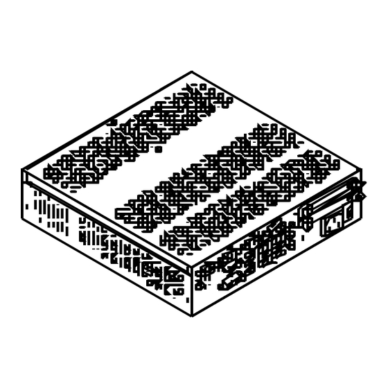
Page 76: Each Component Function
5. Each Component Function 5. Each Component Function Component Name Front View BX-1000-AC POWER SERIAL SERIAL SERIAL LAN A LAN B SATA 1 SATA 2 DVI-D HDMI AC POWER POWER USB2.0 USB3.0 MIC LED ACCESS DVI-D HDMI AC INLET LIN E LIN E Figure 5.1. - Page 77 5. Each Component Function Table 5.1. Component Function Name Function AC POWER SW AC power switch POWER SW Power switch AC INLET AC100-240V AC power input connector POWER LED Power ON display LED ACCESS LED SATA disk access display LED Line in (φ3.5 PHONE JACK) LINE IN LINE OUT...
-
Page 78: Component Function
5. Each Component Function Component Function AC power switch : AC POWER SW This is the AC power switch. You can use this component to turn the AC power supply on or off. Power switch : POWER SW This is the power switch. You can use this component to turn the product power on or off. LED : POWER LED, ACCES LED There are two LED in the front of this product. -
Page 79: Serial-Ata : Sata 1, Sata 2
5. Each Component Function Serial-ATA : SATA 1, SATA 2 The product has two serial ATA 3.0 compliant controllers, allowing a 2.5-inch SATA hard disk drive to the on-board connector using the bundled hard disk bracket. Table 5.3. SATA Connector Connector used SATA connector on the product... -
Page 80: Cfast Connector : Cfast
5. Each Component Function CFast Connector : CFast The CFast (Type I) can be connected. Table 5.4. CFast Connector Connector used CFast connector on the product Pin No. Signal name Pin No. Signal name N.C. N.C. N.C. N.C. N.C. PC10 N.C. -
Page 81: Giga Bit-Ethernet : Lan A, Lan B
5. Each Component Function Giga bit-Ethernet : LAN A, LAN B The BOX-PC is equipped with two channels for giga bit-Ethernet. Network type : 1000BASE-T/100BASE-TX/10BASE-T Transmission speed* : 1000M/100M/10M bps Max. network path length : 100m/segment Controller : LAN A : Intel 82579LM PHY Controller LAN B : Intel 82583V Controller * Operation at 1000Mbps requires a category 5e cable. -
Page 82: Usb 3.0 Ports : Usb 3.0
5. Each Component Function USB 3.0 Ports : USB 3.0 The BOX-PC is equipped with four channels for USB 3.0 interface. The Windows Embedded Standard 2009 model does not support USB 3.0. The USB 3.0 ports operate as USB 2.0 ports. Table 5.6. -
Page 83: Serial Port Interface : Serial A, B, C
5. Each Component Function Serial Port Interface : SERIAL A, B, C The product has five channels of RS-232C compliant serial ports supporting up to a baud rate of 115,200bps with a 16-byte transmission-dedicated data buffer and a 16-byte reception-dedicated data buffer. -
Page 84: Gpio Connector : Dio
5. Each Component Function GPIO Connector : DIO The product is equipped with an interface to which you can connect a remote switch and a GPIO device. GPIO is not isolated. Table 5.10. GPIO Connector Connector used on 9pin D-SUB (female) the product No.4-40UNC Inch screw... - Page 85 5. Each Component Function Usage method When controlling the general purpose I/O ports GPIO0 to GPIO5 and when using I/O, set the data to I/O port addresses 02A8h to 02AAh. Usage procedure (1) GPIO selection … Set port 02A8h to "06h" in order to enable the control of GPIO0 to GPIO5 with port 02A9h.
- Page 86 5. Each Component Function * 02AAh port: General purpose I/O register ― ― GPIO5 GPIO4 GPIO3 GPIO2 GPIO1 GPIO0 Figure 5.6 General purpose I/O (02AAh) Input mode : Read the data from GPIO0 to GPIO5. Even if you set values on GPIO ports Specified as input mode, these values will be ignored.
-
Page 87: Analog Rgb Interface : Rgb
5. Each Component Function Analog RGB Interface : RGB The product is equipped with a connector for use in connecting to an analog RGB display. Table 5.11. Analog RGB Connector HD-SUB 15 pin (FEMALE) Connector type No.4-40UNC Inch screw threads Pin No. -
Page 88: Dvi-D Interface : Dvi-D
5. Each Component Function DVI-D Interface : DVI-D A DVI-D interface is provided. Table 5.12. DVI-D Connector Connector used on DVI-D 25 pin the product Signal Signal Signal Pin No. Pin No. Pin No. name name name DATA2- N.C. N.C. DATA2+ DATA2 SHIELD... -
Page 89: Hdmi Interface : Hdmi
5. Each Component Function HDMI Interface : HDMI A HDMI interface is provided. You can connect an HDMI display. Table 5.13. HDMI Connector 19 pin HDMI Type A (male) Connector type 11 9 7 5 3 1 10 8 6 4 2 Pin No. -
Page 90: Expansion Slots (Bx-1000P2-Ac, Bx-1000P4-Ac)
5. Each Component Function Expansion slots (BX-1000P2-AC, BX-1000P4-AC) BX-1000P2-AC has two expansion slots for the implementation of PCI bus type borad. BX-1000P4-AC has one PCI-Express(x8) slots and three expansion slots for the implementation of PCI bus type borad. Board Dimensions Allowed 240mm(max.) 240mm(max.) 170mm... - Page 91 5. Each Component Function BX-1000 User’s Manual...
-
Page 92: Appendix
6. Appendix 6. Appendix POST Codes Table 6.1. POST Codes < 1 / 3 > POST Description (hex) < Security (SEC) phase > Power on. Reset type detection (software / hardware) AP initialization before microcode loading North Bridge initialization before microcode loading South Bridge initialization before microcode loading OEM initialization before microcode loading Microcode loading... - Page 93 6. Appendix Table 6.1. POST Codes < 2 / 3 > POST Description (hex) CPU DXE initialization is started 64h - 67h CPU DXE initialization (CPU module specific) PCI host bridge initialization North Bridge DXE initialization is started North Bridge DXE SMM initialization is started 6Bh - 6Fh North Bridge DXE initialization (North Bridge module specific) South Bridge DXE initialization is started...
- Page 94 6. Appendix Table 6.1. POST Codes < 3 / 3 > POST Description (hex) USB hot plug PCI bus hot plug Clean-up of NVRAM Configuration Reset (reset of NVRAM settings) B8h - BFh Reserved for future AMI codes C0h - CFh OEM BDS initialization codes ACPI/ASL Checkpoints System is entering S1 sleep state...
-
Page 95: Serial I/O Address And Register Function
6. Appendix SERIAL I/O Address and Register Function The following table lists the I/O addresses in case of SERIAL A. Table 6.2. I/O Address I/O address DLAB Read/Write Register 03F8H Transmitter holding register Receive buffer register Divisor latch register 03F9H Divisor latch register Interrupt enable register 03FAH... - Page 96 6. Appendix Table 6.3. Function of Each Register < 1 / 4 > I/O address Description 03F8H THR: Transmitter Holding Register [DLAB=0] bit7 bit0 Register dedicated to write transmitted data to 03F8H RBR: Reciever Buffer Register [DLAB=O] bit0 bit7 Register dedicated to read received data from 03F8H DLL: Divisor Latch (LSB) [DLAB=1] bit7...
- Page 97 6. Appendix Table 6.3. Function of Each Register < 2 / 4 > I/O address Description 03FAH IIR : Interrupt Identification Register Interrupt details 1: Do not generate interrupts 0: Generate interrupts bit2 bit1 bit0 Priority Description Interrupts are not generated. Generated by overrun, parity, framing error or break 1 (high) interrupt.
- Page 98 6. Appendix Table 6.3. Function of Each Register < 3 / 4 > I/O address Description 03FCH MCR: Modem Control Register Loop IRQ RTS DTR 0 : Inactive [HIGH] 1 : Active [LOW] RTS 0 : Inactive [HIGH] 1 : Active [LOW] Interrupt control bit 0 : Disable...
- Page 99 6. Appendix Table 6.3. Function of Each Register < 4 / 4 > I/O address Description 03FEH MSR : Modem Status Register DSR CTS DDCD TERI DDSR DCTS Delta CTS Delta DSR Trailing edge RI Delta data carrier detect 03FFH SCR : Scratchpad Register This is an 8-bit, readable/writable register which is available to the user to allow data to be saved temporarily.
- Page 100 6. Appendix Baud Rate Settings A baud rate is set by software by dividing the clock input (1.8432MHz). The baud rate in terms of hardware can be set to a maximum of 115,200 bps for SERIAL A, B, C. The baud rates available in practice depend on the operating environment (cable, software, etc.).
-
Page 101: Watch-Dog-Timer
6. Appendix Watch-Dog-Timer The watchdog timer serves as a safeguard against possible system lock-up in your industrial computer system. In most industrial environments, there are heavy equipment, generators, high-voltage power lines, or power drops that have adverse effects on your computer system. For instance, when a power drop occurs, it could cause the CPU to come to a halt state or enter into an infinite loop, resulting in a system lock-up. - Page 102 6. Appendix (2) Example programming The following example is written in Intel8086 assembly language. ;=============== ;<WDT Initial> ;=============== ;------------------------------------------- ;Enter the extended function mode ;------------------------------------------- MOV DX,2EH MOV AL,87H OUT DX,AL OUT DX,AL ;------------------------------------------------ ;Select logical device GPIO(number 9) ;------------------------------------------------- MOV DX,2EH MOV AL,07H OUT DX,AL...
- Page 103 6. Appendix MOV DX,2FH MOV AL,0DH OUT DX,AL ;----------------------------------- ;Set timer unit : second ;----------------------------------- MOV DX,2EH MOV AL,F5H OUT DX,AL MOV DX,2FH MOV AL,00H OUT DX,AL ;------------------------------------------ ;Exit the extended function mode ;------------------------------------------ MOV DX,2EH MOV AL,AAH OUT DX,AL ;================================ ;<WDT START : counter set and a start >...
- Page 104 6. Appendix ;Exit the extended function mode ;----------------------------------- MOV DX,2EH MOV AL,AAH OUT DX,AL ;============== ;<WDT STOP> ;============== ;----------------------------------- ;Enter the extended function mode ;----------------------------------- MOV DX,2EH MOV AL,87H OUT DX,AL OUT DX,AL ;----------------------------------- ;Select logical device WDT(number 8) ;----------------------------------- MOV DX,2EH MOV AL,07H OUT DX,AL...
-
Page 105: Battery
6. Appendix Battery Battery Specification This product uses the following battery. - Type : Lithium primary battery - Nominal voltage : 3V - Model : BR-1/2AA - Nominal capacity : 1000mAh - Maker : Panasonic - Lithium content : 1g or less Removing the battery Remove the battery according to the following figure. -
Page 106: List Of Options
7. List of Options List of Options CFast card CFS-8GB-A : CFast card 8GB CFS-16GB-A : CFast card 16GB PC-HDD 100GS-2 : 2.5inch SATA HDD 100GB For more information on this options, see the Contec’s website. BX-1000 User’s Manual... - Page 107 3-9-31, Himesato, Nishiyodogawa-ku, Osaka 555-0025, Japan Japanese http://www.contec.co.jp/ English http://www.contec.com/ Chinese http://www.contec.com.cn/ No part of this document may be copied or reproduced in any form by any means without prior written consent of CONTEC CO., LTD. [05122017] [10062014] Management No. NA05640 [05122017_rev10] Parts No. LYUZ601...
Need help?
Do you have a question about the IPC SERIES and is the answer not in the manual?
Questions and answers