
Related Manuals for Contec BX-955SD-DC6000


Summary of Contents for Contec BX-955SD-DC6000
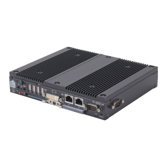
- Page 1 IPC Series BOX-PC 955S Series Fanless, Atom N2600 CFast, DC input User’s Manual CONTEC CO., LTD.
-
Page 2: Check Your Package
The product consists of the items listed below. Check, with the following list, that your package is complete. If you discover damaged or missing items, contact your retailer. If you use driver&utility software set, download it from the CONTEC’s Web site. Product Configuration List... -
Page 3: Copyright
No part of this document may be copied or reproduced in any form by any means without prior written consent of CONTEC CO., LTD. CONTEC CO., LTD. makes no commitment to update or keep current the information contained in this document. -
Page 4: Table Of Contents
Table of Contents Check your package ............................. i Copyright ..............................ii Trademarks ..............................ii Table of Contents ............................iii INTRODUCTION About the Product............................1 Features ..............................1 Supported OS ............................2 Customer Support ............................3 Web Site..............................3 Limited One-Year Warranty ........................3 How to Obtain Service .......................... - Page 5 Side View ............................23 System Configuration ..........................24 Component Function ..........................25 LED: POWER, ACCESS, STATUS ....................25 DC Power Input Connector : DC-IN ....................25 POWER SW ............................26 Line out Interface: LINE OUT ......................26 MIC in Interface: MIC ........................26 Giga bit-Ethernet: LAN A –...
- Page 6 Save & Exit ..............................60 POST Beep..............................62 Position and Settings of the ROM Clear Switches ................. 63 APPENDIX Memory Map ............................. 65 I/O Port Addresses ............................ 66 Interrupt Level List ........................... 67 POST Codes ............................... 68 SERIAL I/O Address and Register Function ..................70 Watch-Dog-Timer .............................
- Page 7 BX-955Sx Series User’s manual...
-
Page 8: Introduction
This product is available in the following 5 models : Atom Processor N2600 1.6GHz - Base model with Intel BX-955SD-DC6000 (Memory 2GB, without OS, CFast card) - Windows Embedded Standard 2009 model, VGA type with Intel Atom Processor N2600 1.6GHz... -
Page 9: Supported Os
1. Introduction Contributes to Reductions in Running Cost and Energy Usage Although this product guarantees sufficient performance, it sports low power consumption. The slitless and fanless design leads to a reduction in maintenance and inspection work. What's more, as a resource-saving PC, this product assists our customers in their implementations of plans to reduce running costs and energy usage. -
Page 10: Customer Support
You can download updated driver software and differential files as well as sample programs available in several languages. Note! For product information Contact your retailer if you have any technical question about a CONTEC product or need its price, delivery time, or estimate information. Limited One-Year Warranty CONTEC products are warranted by CONTEC CO., LTD. -
Page 11: Safety Precautions
1. Introduction Safety Precautions Understand the following definitions and precautions to use the product safely. Safety Information This document provides safety information using the following symbols to prevent accidents resulting in injury or death and the destruction of equipment and resources. Understand the meanings of these labels to operate the equipment safely. - Page 12 Avoid installation in a location where people may come into contact with that section. CONTEC does not provide any guarantee for the integrity of data on CFast card. Always disconnect the power cable from the receptacle before mounting or removing the expansion board, or before connecting or disconnecting any connector.
- Page 13 1. Introduction FCC PART 15 Class A Notice NOTE This equipment has been tested and found to comply with the limits for a Class A digital device, pursuant to part 15 of the FCC Rules. These limits are designed to provide reasonable protection against harmful interference when the equipment is operated in a commercial environment.
-
Page 14: System Reference
Full-scale input level 1.5Vrms(Typ.) CFast card slot 2 slots, CFast CARD Type I , bootable BX-955SD-DC6000 : - BX-955S-DC6311, BX-955SD-DC6311 : CFast is finished mounting. (4GB) BX-955SD-DC6312 : CFast is finished mounting. (8GB) BX-955SD-DC631N : CFast is finished mounting. (16GB) - Page 15 2. System Reference Table 2.1. Functional Specifications < 2 / 2 > Model BX-955Sx-DC6xxx 1000BASE-T/100BASE-TX/10BASE-T RJ-45 connector x 2(Wake On LAN support) Controller LAN-A : Realtek 8111E Controller LAN-B : Realtek 8111E Controller USB I/F 4channels (USB 2.0-compliant) Keyboard/mouse I/F None *5 General-purpose I/O None...
-
Page 16: Power Management Features
2. System Reference Table 2.2. Installation Environment Requirements Model BX-955Sx-DC6xxx Operating temperature 0 - 50°C (When using 1000BASE-T : 0 - 45°C) Storage temperature -10 - 60°C Humidity 10 - 90%RH (No condensation) Floating dust particles Not to be excessive Corrosive gases None AC line / ±2kV *2,... -
Page 17: Power Requirements
2. System Reference Power Requirements Your system requires a clean, steady power source for reliable performance of the high frequency CPU on the product, the quality of the power supply is even more important. For the best performance makes sure your power supply provides a range of 10.8 V minimum to 31.2 V maximum DC power source. Power Consumption For typical configurations, the CPU card is designed to operate with at least a 60W power supply. -
Page 18: Physical Dimensions
2. System Reference Physical Dimensions BX-955Sx-DC6xxx M4 scr ews *1 8-φ5 M3 sc rews *2 [m m] C F A 12 - 24 ST A TU S V D C Figure 2.1. BX-955Sx-DC6xxx CAUTION *1 : The length (L) from the tip of M4 boss to the M4 screw tip should be 5mm or less. If not doing so, it may be exactly fixed. - Page 19 2. System Reference BX-955Sx Series User’s manual...
-
Page 20: Hardware Setup
3. Hardware Setup 3. Hardware Setup Before Using the Product for the First Time Follow the next steps to set up this product: STEP1 By referring to the information in this chapter, install, connect and set this product. STEP2 Connect cables. Connect the cable of necessary external devices, such as keyboard and a display, to this product using appropriate cables. -
Page 21: Hardware Setup
3. Hardware Setup Hardware Setup Before you start, be sure that the power is turned off. Remove only those screws that are explained. Do not move any other screw. Attaching the CFast Attachment Fittings (1) After inserting a CFast Card, fasten the bundled CFast attachment fittings with a screw. Figure 3.1. -
Page 22: Attaching The Fg
3. Hardware Setup Attaching the FG (1) Use screws to attach the FG. * Attached screw (M3 x 8) Figure 3.3. Attaching the FG CAUTION The FG pin of this product is connected to the GND signal of the DC power connector (DC-IN). Note that the connection cannot be cut off. -
Page 23: Fastening The Cable
3. Hardware Setup Fastening the Cable This product comes with clamps for fixing cables. Fastening the LINEOUT, USB Cable (1) The system unit has a hole for attaching cable clamp to USB removal prevention fitting. Using a cable clamp for a cable with lock-less connector, such as the LINEOUT and USB Cable, prevents the connector from being unplugged. - Page 24 3. Hardware Setup You can fix this product to VESA holes with a pitch of 75 x 75 or 100 x 100 by using the following VESA attachment metal fittings. The liquid crystal display is possible and weight that can be the installation it is 8 kg or less possible. The VESA attachment metal fittings are optional products.
- Page 25 When a CONTEC FPD-H75XT-DC1 [weight: 3.6 kg, pitch: 75 mm] is attached, the vibration resistance and impact resistance are the values shown below.
-
Page 26: Installation Requirements
3. Hardware Setup Installation Requirements Be sure that the operating temperature is within the range specified in the installation environment requirement by making space between the product and device that generates heat or exhaust air. BX-955Sx-DC6xxx Installable directions at operating temperature 0 - +50 ° C (When using 1000BASE-T : 0 - +45 ° C) Connector 12 - 24 S TA TUS... - Page 27 3. Hardware Setup Distances between this product and its vicinity 50mm or more 100 mm or more 50mm or more 12 - 2 4 STATUS Figure 3.8. Distances between this product and its vicinity CAUTION Do not install this product into the fully-sealed space except the case in which the internal temperature is adjustable by equipment such as air conditioner.
- Page 28 3. Hardware Setup Operating temperature In this product, the operating temperature is decided from the multiple measurement points as shown below. When making use of the product, the air current should be adjusted to prevent that all the temperatures measured at the measurement points exceed the specified temperature. <Vertical installation>...
- Page 29 3. Hardware Setup BX-955Sx Series User’s manual...
-
Page 30: Each Component Function
4. Each Component Function Each Component Function Component Name Front View BX-955Sx-DC6xxx LINE POWER DVI-I STATUS 12 - 24 STATUS DC-IN LAN A LAN B SERIAL A ACCESS LED POWER CFast2 CFast1 Figure 4.1. Component Name < 1 / 2 > Side View BX-955Sx-DC6xxx SERIAL B... -
Page 31: System Configuration
4. Each Component Function System Configuration BX-955Sx-DC6xxx LINE OUT USB2.0 FD drive Display Serial port (A, B) CFast LAN port card (1, 2) (A, B) Printer USB device such as CD-ROM drive .,etc Figure 4.2. System Configuration BX-955Sx Series User’s manual... -
Page 32: Component Function
4. Each Component Function Component Function LED: POWER, ACCESS, STATUS There are 3 LED in front of this product. Table 4.2. Display Contents of LED LED name State Display contents POWER LED Indicates that this product is switched off. ON (Green) Indicates that this product is switched on. -
Page 33: Power Sw
A MIC input connector is provided. You can plug a microphone to this connector for sound input. Audio driver The audio driver is required to use the microphone input and line output interfaces. Install the appropriate audio driver for your OS from the CONTEC’s Web site. BX-955Sx Series User’s manual... -
Page 34: Giga Bit-Ethernet: Lan A - B
10M : Off, 100M : Green, 1000M : Orange LAN drivers Install the appropriate audio driver for your OS from the CONTEC’s Web site. CAUTION When using any OS other than pre-installed one, LAN-1 and LAN-2 may not be assigned to silk print “LAN-A”... -
Page 35: Usb Ports
4. Each Component Function USB Ports This product is equipped with 4 channels for USB 2.0 interface. Table 4.5. USB Connector Pin No. Function USB_VCC USB- USB+ USB_GND BX-955Sx Series User’s manual... -
Page 36: Serial Port Interface : Serial A - B
4. Each Component Function Serial Port Interface : SERIAL A - B SERIAL A,B The product has 2 channels of serial ports supporting up to a baud rate of 115,200bps with a 16-byte transmission-dedicated data buffer and a 16-byte reception-dedicated data buffer. You can use “Chapter 5 BIOS Setup”... -
Page 37: Dvi Interface : Dvi
A DVI interface is provided. You can use it to connect a CRT (even a D-SUB 15 pin connector is acceptable by using the bundled DVI-analog RGB adapter) or a CONTEC Panel Link display. The connector is named DVI (DVI-I 29-pin connector). - Page 38 VSYNC DDC CLK Display driver Install the appropriate audio driver for your OS from the CONTEC’s Web site CAUTION For Windows Embedded Standard 2009, the primary display cannot be changed. If you connect to the RGB connector displays that process the unused pins in a special manner, the PC may not start.
-
Page 39: Cfast Card Connector (Primary Ide Connection) : Cfast1
4. Each Component Function CFast Card Connector (Primary IDE Connection) : CFast1 The CFast Card (Type I) can be connected. The CFast card connector doesn't support hot plug. Please neither pulling out opening of CFast in the state of power supply ON of this product nor come in contact with CFast. This product may malfunction or cause a failure. -
Page 40: Bios Setup
5. BIOS Setup BIOS Setup Introduction This chapter discusses AMI’s Setup program built into the FLASH ROM BIOS. The Setup program allows users to modify the basic system configuration. This special information is then stored in FLASH ROM so that it retains the Setup information when the power is turned off. The rest of this chapter is intended to guide you through the process of configuring your system using Setup. -
Page 41: Using Setup
5. BIOS Setup Using Setup In general, you use the arrow keys to highlight items, press <Enter> to select, use the “+” and “-” keys to change entries, press <F1> for help and press <Esc> to quit. The following table provides more detail about how to navigate in the Setup program using the keyboard. -
Page 42: Main Menu
5. BIOS Setup Main Menu Once you enter the AMI BIOS Setup Utility, the Main Menu will appear on the screen. By pressing the left or right arrow keys, you will be able to move the tab of each item. Figure 5.1. -
Page 43: Main
5. BIOS Setup Main Use this menu to check basic system configuration. Settings that can be configured in the Main menu are described in the table below. Table 5.2 Main Menu Selections Item Options Description Set the system date. Note that the ‘Day’ System Date Month / Day / Year automatically changes when you set the... -
Page 44: Advanced
5. BIOS Setup Advanced Use this menu to set the detailed function that can setting to your system. Figure 5.2 Advanced menu Settings that can be configured in the Advanced menu are described in the table below. Table 5.3 Advanced Menu Selections Item Options Description... - Page 45 5. BIOS Setup USB Configuration Use this menu to specify USB Configuration. Super I/O Configuration Use this menu to specify Super I/O Configuration. Hardware Monitor Use this menu to specify Hardware Monitor. PPM Configuration Specify the Intel energy-saving function settings. BX-955Sx Series User’s manual...
-
Page 46: Pci Subsystem Settings
5. BIOS Setup PCI Subsystem Settings Use this menu to specify PCI Subsystem Settings. Figure 5.3 PCI Subsystem Settings Items that can be configured for PCI subsystem settings are described in the table below. Table 5.4 PCI Subsystem Settings Item Options Description In case of multiple Option ROMs (Legacy... -
Page 47: Acpi Settings
5. BIOS Setup ACPI Settings Use this menu to specify ACPI power management settings. Figure 5.4 ACPI Settings Settings that can be configured in the ACPI Settings are described in the table below. Table 5.5 ACPI Settings Item Options Description Suspend Disabled Selects the ACPI sleep mode used when the system S1 (CPU Stop Clock) -
Page 48: Cpu Configuration
5. BIOS Setup CPU Configuration Use this menu to specify CPU Configuration. Figure 5.5 CPU Configuration Settings that can be configured in the CPU Configuration are described in the table below. Table 5.6 CPU Configuraiton Item Options Description Enables or disables the Hyper-Threading Disabled Hyper-Threading function. -
Page 49: Ide Configuration
5. BIOS Setup IDE Configuration Figure 5.6 IDE Configuration Settings that can be configured in the IDE Configuration are described in the table below. Table 5.7 IDE Configuraiton Item Options Description Enables or disables the SATA port (for Disabled SATA Controller(s) the CFast card). -
Page 50: Usb Configuration
5. BIOS Setup USB Configuration Figure 5.7 USB Configuration Settings that can be configured in the USB Configuration are described in the table below. Table 5.8 USB Configuraiton Item Options Description USB Devices : Displays the names of the connected USB devices. Enabled Sets the USB keyboard support for operating Legacy USB Support... -
Page 51: Super I/O Configuration
5. BIOS Setup Super I/O Configuration Figure 5.8 Super I/O Configuration Settings that can be configured in the Super I/O Configuration are described in the table below. Table 5.9 Super I/O Configuration Item Options Description Sets whether to start the system at the same point in time that the power supply starts. -
Page 52: Serial Port A Configuration
5. BIOS Setup Serial Port A Configuration Figure 5.9 Serial Port A Configuration Settings that can be configured in the Serial Port A Configuration are described in the table below. Table 5.10 Serial Port A Configuration Item Options Description Disabled Enable or Disable Serial Port Serial Port Enabled... -
Page 53: Serial Port B Configuration
5. BIOS Setup Serial Port B Configuration Figure 5.10 Serial Port B Configuration Settings that can be configured in the Serial Port B Configuration are described in the table below. Table 5.11 Serial Port B Configuration Item Options Description Disabled Enable or Disable Serial Port Serial Port Enabled... -
Page 54: Hardware Monitor
5. BIOS Setup Hardware Monitor Use this menu to check CPU temperature, system temperature, input voltage, and other system conditions. Figure 5.11 Hardware Monitor BX-955Sx Series User’s manual... -
Page 55: Ppm Configuration
5. BIOS Setup PPM Configuration Figure 5.12 PPM Configuration Settings that can be configured in the PPM Configuration are described in the table below. Table 5.12 PPM Configuration Item Options Description Enables or disables the Intel Disabled SpeedStep function. When this is EIST Enabled set to "Enabled,"... -
Page 56: Chipset
5. BIOS Setup Chipset Use this menu to specify advanced chipset settings. Figure 5.13 Chipset menu The following sub items are available: Host Bridge Use this menu to specify Host Bridge settings. South Bridge Use this menu to specify South Bridge. BX-955Sx Series User’s manual... -
Page 57: Host Bridge
5. BIOS Setup Host Bridge Figure 5.14 Host Bridge The following sub items are available: Memory Frequency and Timing Intel IGD Configuration BX-955Sx Series User’s manual... -
Page 58: Memory Frequency And Timing
5. BIOS Setup Memory Frequency and Timing Figure 5.15 Memory Frequency and Timing Settings that can be configured in the Memory Frequency and Timing are described in the table below. Table 5.13 Memory Frequency and Timing Item Options Description Disabled Enable or disable MRC fast boot. -
Page 59: Intel Igd Configuration
* After you install the OS, do not change this setting. Selects the display for the BIOS SETUP screen. This is set as shown below when the product is shipped. BX-955SD-DC6000 : CRT+DVI Boot Display Type BX-955S-DC6311 : CRT CRT+DVI BX-955SD-DC6311 : DVI... -
Page 60: South Bridge
5. BIOS Setup South Bridge Figure 5.17 South Bridge Settings that can be configured in the South Bridge are described in the table below. Table 5.15 South Bridge Item Options Description Onboard LAN A Disabled Enable / Disable Onboard LAN A Enabled Controller Controller. - Page 61 5. BIOS Setup Item Options Description Disabled 50 C/122 F 55 C/131 F Sets the temperature at which to start 60 C/140 F Threshold Temperature reducing the clock when the CPU 65 C/149 F temperature increases. 70 C/158 F 75 C/167 F 70 C 176 F The following sub items are available: TPT Devices...
-
Page 62: Tpt Devices
5. BIOS Setup TPT Devices Figure 5.18 TPT Devices Settings that can be configured in the TPT Devices are described in the table below. Table 5.16 TPT Devices Item Options Description Enables or disables the Azalia sound Disabled Azalia Controller controller. - Page 63 5. BIOS Setup Item Options Description (When the USB mode is set to "By Disabled Controllers".) UHCI #1 (ports 0 and 1) Enabled Enables or disables USB ports 0 and 1. Normally do not change this setting. (When the USB mode is set to "By Disabled Controllers".) UHCI #2 (ports 2 and 3)
-
Page 64: Boot
5. BIOS Setup Boot Figure 5.19 Boot menu Use this menu to specify settings related to system startup. The following items are available: Table 5.17 Boot Item Options Description Sets the timeout time (in seconds) after which the system switches to the BIOS Setup Prompt Timeout 1 - 65535 setup screen. - Page 65 5. BIOS Setup CAUTION In the Boot Option #x list, the same device may be displayed as shown below. (1) USB Disk (2) UEFI : USB Disk In this situation, select (1) to perform legacy booting in which the disk is assumed to be MBR formatted and (2) to perform UEFI booting in which the disk is assumed to be GPT formatted.
-
Page 66: Security
5. BIOS Setup Security Use this menu to configure system security settings. Figure 5.20 Security menu The following items are available: Administrator Password When you press <Enter> on this item, you are required to input the password as below. Create New Password [**** Confirm New Password [****... -
Page 67: Save & Exit
5. BIOS Setup Save & Exit Use this menu to load/save settings changes, and exit the setup menu. Figure 5.21 Save & Exit menu The following items are available: Save Changes and Exit When you press <Enter> on this item you get a confirmation dialog box with a message similar to: Save &... - Page 68 5. BIOS Setup Save Changes and Reset When you press <Enter> on this item you get a confirmation dialog box with a message similar to: Save & Reset Save configuration and reset? [Yes] [No] Pressing [Yes] saves any changes made in FLASH ROM and reboots the system. The next time the computer is booted, the BIOS configures the system based on the configuration stored in FLASH ROM.
-
Page 69: Post Beep
5. BIOS Setup Save as User Defaults When you press <Enter> on this item you get a confirmation dialog box with a message similar to: Save Values as User Defaults Save Configuration? [Yes] [No] Pressing [Yes] saves the current settings as the user default settings in FLASH ROM and takes you back to the setup menu. -
Page 70: Position And Settings Of The Rom Clear Switches
5. BIOS Setup Position and Settings of the ROM Clear Switches If the BIOS settings cause unexpected system start errors, you can set the ROM clear switches and start the system to disable the BIOS settings and start the system. During normal operation, leave the ROM clear switches in their factory default settings (HSW2-1 is in the ON position). - Page 71 5. BIOS Setup BX-955Sx Series User’s manual...
-
Page 72: Appendix
6. Appendix 6. Appendix Memory Map Table 6.1. Memory Map Memory Segments Comments 00000h - 9FFFh 0 - 640K DOS Region A0000h – BFFFFh Video Buffer B0000h - B7FFFh Monochrome Adapter range C0000h – CFFFFh Video BIOS D0000h – DFFFFh Expansion Area E0000h –... -
Page 73: I/O Port Addresses
6. Appendix I/O Port Addresses Table 6.2. I/O Port Addresses < 1 / 2 > Address Size Description 0000 - 001F 32 bytes DMA controller 0020 - 0021 2 bytes Interrupt controller 0024 - 0025 2 bytes Interrupt controller 0028 - 0029 2 bytes Interrupt controller 002C –... -
Page 74: Interrupt Level List
6. Appendix Table 6.2. I/O Port Addresses < 2 / 2 > Address Size Description 03F6 1 byte IDE / SATA controller, PCI 03F8 – 03FF 8 bytes SERIAL A 0400 – 043F 64 bytes Power management 04D0 – 04D1 2 bytes Interrupt controller 0500 –... -
Page 75: Post Codes
6. Appendix POST Codes Table 6.4. POST Codes < 1 / 3 > POST Description (hex) < Security (SEC) phase > Power on. Reset type detection (software / hardware) AP initialization before microcode loading North Bridge initialization before microcode loading South Bridge initialization before microcode loading OEM initialization before microcode loading Microcode loading... - Page 76 6. Appendix Table 6.4. POST Codes < 2 / 3 > POST Description (hex) North Bridge DXE initialization is started North Bridge DXE SMM initialization is started 6Bh - 6Fh North Bridge DXE initialization (North Bridge module specific) South Bridge DXE initialization is started South Bridge DXE SMM initialization is started South Bridge devices initialization 73h –...
-
Page 77: Serial I/O Address And Register Function
6. Appendix Table 6.4. POST Codes < 3 / 3 > POST Description (hex) ACPI/ASL Checkpoints System is entering S1 sleep state System is entering S2 sleep state System is entering S3 sleep state System is entering S4 sleep state System is entering S5 sleep state System is waking up from the S1 sleep state System is waking up from the S2 sleep state... - Page 78 6. Appendix Table 6.6. Function of Each Register < 1 / 4 > I/O address Description 03F8H THR: Transmitter Holding Register [DLAB=0] bit0 bit7 Register dedicated to write transmitted data to 03F8H RBR: Reciever Buffer Register [DLAB=O] bit0 bit7 Register dedicated to read received data from 03F8H DLL: Divisor Latch (LSB) [DLAB=1] bit0...
- Page 79 6. Appendix Table 6.6. Function of Each Register < 2 / 4 > I/O address Description 03FAH IIR : Interrupt Identification Register Interrupt details 1: Do not generate interrupts 0: Generate interrupts bit2 bit1 bit0 Priority Description Interrupts are not generated. Generated by overrun, parity, framing error or break 1 (high) interrupt.
- Page 80 6. Appendix Table 6.6. Function of Each Register < 3 / 4 > I/O address Description 03FCH MCR: Modem Control Register Loop IRQ RTS DTR 0 : Inactive [HIGH] 1 : Active [LOW] RTS 0 : Inactive [HIG H] 1 : Active [LOW] Interrupt control bit 0 : Disable...
- Page 81 6. Appendix Table 6.6. Function of Each Register < 4 / 4 > I/O address Description 03FEH MSR : Modem Status Register DSR CTS DDCD TERI DDSR DCTS Delta CTS Delta DSR Trailing edge RI Delta data carrier detect 03FFH SCR : Scratchpad Register This is an 8-bit, readable/writable register which is available to the user to allow data to be saved temporarily.
- Page 82 6. Appendix Baud Rate Settings A baud rate is set by software by dividing the clock input (1.8432MHz). The baud rate in terms of hardware can be set to a maximum of 115,200 bps for SERIAL A, B, C, D. The baud rates available in practice depend on the operating environment (cable, software, etc.).
-
Page 83: Watch-Dog-Timer
6. Appendix Watch-Dog-Timer The watchdog timer serves as a safeguard against possible system lock-up in your industrial computer system. In most industrial environments, there are heavy equipment, generators, high-voltage power lines, or power drops that have adverse effects on your computer system. For instance, when a power drop occurs, it could cause the CPU to come to a halt state or enter into an infinite loop, resulting in a system lock-up. - Page 84 6. Appendix (2) Example programming The following example is written in Intel8086 assembly language. ;=============== ;<WDT Initial> ;=============== ;------------------------------------------- ;Enter the extended function mode ;------------------------------------------- MOV DX,2EH MOV AL,87H OUT DX,AL OUT DX,AL ;----------------------------------- ;Set WDT function at pin89 ;----------------------------------- MOV DX,2EH MOV AL,2BH OUT DX,AL...
- Page 85 6. Appendix MOV AL,00H OUT DX,AL ;------------------------------------------ ;Exit the extended function mode ;------------------------------------------ MOV DX,2EH MOV AL,AAH OUT DX,AL ;================================ ;<WDT START : counter set and a start > ;================================ ;--------------------------------------------- ;Enter the extended function mode ;--------------------------------------------- MOV DX,2EH MOV AL,87H OUT DX,AL OUT DX,AL ;------------------------------------------------...
- Page 86 6. Appendix ;============== ;<WDT STOP> ;============== ;----------------------------------- ;Enter the extended function mode ;----------------------------------- MOV DX,2EH MOV AL,87H OUT DX,AL OUT DX,AL ;----------------------------------- ;Select logical device WDT(number 8) ;----------------------------------- MOV DX,2EH MOV AL,07H OUT DX,AL MOV DX,2FH MOV AL,08H OUT DX,AL ;----------------------------------- ;Stop count down of WDT ;-----------------------------------...
-
Page 87: Status Led
6. Appendix Status LED The operation of the status LED can be controlled from user applications. The following is a sample program created in an MS-DOS environment with MSC version 8.03. The status LED blinks once per second for approximately 10 seconds. #include <stdio.h>... - Page 88 6. Appendix outp( IDX, 0x87 ); /* CLOSE WD83627 CR */ void close_dev( void ) IOWAIT; outp( IDX, 0xaa ); main( int argc, char *argv[] ) time_t otm,rtm, rtm2; open_dev(); set_ldev( 9 ); set_reg( 0x30, get_reg(0x30) | 0x08 ); // Enable GPIO5x set_reg( 0xe0, get_reg(0xe0) &...
-
Page 89: Battery
6. Appendix Battery Battery Specification This product uses the following battery. - Type : Lithium primary battery - Model : BR-1/2AA - Maker : Panasonic - Nominal voltage : 3V - Nominal capacity : 1000mAh - Lithium content : 1g or less Removing the battery Remove the battery according to the following figure. -
Page 90: List Of Options
CFast card CFS-4GB-A CFast card 4GB CFS-8GB-A CFast card 8GB CFS-16GB-A CFast card 16GB Bracket BX-BKT-VESA02 Bracket for VESA (“75 x 75” - “100 x 100”) * For more information on this options, see the Contec’s website. BX-955Sx Series User’s manual... - Page 91 3-9-31, Himesato, Nishiyodogawa-ku, Osaka 555-0025, Japan Japanese http://www.contec.co.jp/ English http://www.contec.com/ Chinese http://www.contec.com.cn/ No part of this document may be copied or reproduced in any form by any means without prior written consent of CONTEC CO., LTD. [12022016] [05302013] Management No. NA02683 12022016_rev7 Parts No. LYQM447...
Need help?
Do you have a question about the BX-955SD-DC6000 and is the answer not in the manual?
Questions and answers