Contec IPC Series User Manual
Flat panel display non face-plate type dc12v, 10.4"/12.1"/15.0"-tft, lvds
Hide thumbs
Also See for IPC Series:
- User manual (107 pages) ,
- Operational manual (87 pages) ,
- Manual (75 pages)

Subscribe to Our Youtube Channel
Related Manuals for Contec IPC Series


Summary of Contents for Contec IPC Series
- Page 1 IPC Series FLAT PANEL DISPLAY Non Face-Plate Type (DC12V, 10.4"-TFT, LVDS) FPD-M75VT-DC1 (DC12V, 12.1"-TFT, LVDS) FPD-L75ST-DC1 (DC12V, 15.0"-TFT, LVDS) FPD-H75XT-DC1 User’s Manual CONTEC CO.,LTD.
-
Page 2: Check Your Package
Product guide EU/FCC Declaration Conformity Serial number label (Note) The manual of this product is being offered as PDF file on the CONTEC’s Web site. Each cable for this product is not bundled. Purchase it separately. Three-point sems Sealing washer... -
Page 3: Trademarks
No part of this document may be copied or reproduced in any form by any means without prior written consent of CONTEC CO., LTD. CONTEC CO., LTD. makes no commitment to update or keep current the information contained in this document. -
Page 4: Table Of Contents
Table of Contents Check your package ..........................i Copyright ............................ii Trademarks ............................ii Table of Contents ..........................iii INTRODUCTION About the Product ..........................1 Features ............................1 Customer Support ..........................2 Web Site ............................2 Limited One-Year Warranty ....................... 2 How to Obtain Service........................ - Page 5 CONNECTION TO THE HOST COMPUTER LVDS Interface Connection ......................25 DVI-D Interface Connection ......................30 Touch Panel Data Communications ....................31 POWER SUPPLY CONNECTION DC Power Supply Input Connector : DC-IN ................33 AC Adapter Jack ........................34 AC adapter code removal prevention fitting ..................34 LED INDICATORS TOUCH PANEL DISPLAY MODE...
-
Page 6: Introduction
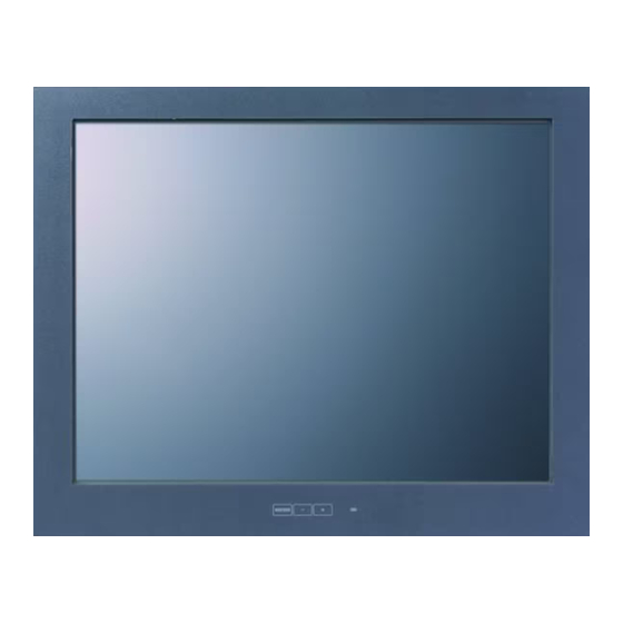
About the Product These products are two inputs (LVDS or DVI-D sign) compatible, embedded type (open-framed), TFT LCD display unit for use with host computers such as the CONTEC IPC series and SBCs (single board computers). Touch panel is available via RS-232C (Built-in video cable) or USB connection. -
Page 7: Customer Support
You can download updated driver software and differential files as well as sample programs available in several languages. Note! For product information Contact your retailer if you have any technical question about a CONTEC product or need its price, delivery time, or estimate information. Limited One-Year Warranty CONTEC Products are warranted by CONTEC CO., LTD. -
Page 8: Safety Information
Protect the touch panel against shock to prevent damage. CONTEC is not liable for a product that has been modified by the user. When the surface or frame of the touch panel has become dirty, wipe it with neutral detergent. Do not wipe the touch panel with thinner, alcohol, ammonia, or a strong chlorinated solvent. - Page 9 300g of force at a rate of two presses per second). CONTEC accepts your request for replacing each consumable in these products as a request for repair (at an additional cost). Contact your local retailer or CONTEC sales office.
-
Page 10: Specifications
2. Specifications 2. Specifications Function Specifications Table 2.1. Function Specifications Specification Item FPD-M75VT-DC1 FPD-L75ST-DC1 FPD-H75XT-DC1 Screen Assembly type Embedded type Screen size 12.1 inches 15.0 inches 10.4 inches Number of pixels 640 x 480 dots 800 x 600 dots 1024 x 768 dots Display type TFT Color LCD Number of colors... -
Page 11: General Specifications
2. Specifications Table 2.2. Power Supply Specifications Specification Item FPD-M75VT-DC1 FPD-L75ST-DC1 FPD-H75XT-DC1 Power supply input part Power supply connector 4-pin connector for +12 - 24VDC power supply AC adapter jack Corresponding to +12 (±5%) VDC output AC adapter Input power supply voltage +12V-24VDC±5%... -
Page 12: Optical Display Specifications
2. Specifications Optical Display Specifications Table 2.4. Optical Display Specifications Specifications (25ºC Typ. Value) Item Condition FPD-M75VT-DC1 FPD-L75ST-DC1 FPD-H75XT-DC1 Visual 50deg 50deg 50deg φ=180° angle Display 60deg 70deg 70deg (vertical) φ=0° CR≥10 Visual 70deg 70deg 70deg φ=+90° angle monochrome 70deg 70deg 70deg (horizontal) -
Page 13: Physical Dimensions
2. Specifications Physical Dimensions FPD-M75VT-DC1 8-M4 TAP (Maximum tapping length : 5mm) φ4.5 XXXXXXXXXXXXXXXXXX M O DEL : S ERIAL N o. : XXXXXX XXXXXXX INP UT : XXXXXX XXXXXXXX XXXXXXXX 2-M3 TAP 6-M3 TAP (Maximum (Maximum tapping tapping length : 4mm) length : 5mm) [mm] Figure 2.2. - Page 14 2. Specifications FPD-H75XT-DC1 φ8-4.5 XXXXXXXXXXXXXXXXXX MODEL : SERIAL No. : XXXXXXXXXXXXX INP UT : XXXXXXXXXXXXXXXXXXXXXX 8-M3 TAP 304.1(ACTIVE AREA) (Maximum tapping length : 4mm) [mm] Figure 2.4. Physical Dimensions of Main Unit (FPD-H75XT-DC1) FPD-M75VT-DC1, FPD-L75ST-DC1, FPD-H75XT-DC1...
- Page 15 2. Specifications FPD-M75VT-DC1, FPD-L75ST-DC1, FPD-H75XT-DC1...
-
Page 16: Part Names
3. Part Names 3. Part Names Part Names Screen & Touch panel Back Right side Left side USB touch panel connector LDVS connector DVI-D connector Dip switch MODEL : XXXXXXXXXXXXXXXXXX SERIAL No. : XXXXXXXXXXXXX INPUT : XXXXXXXXXXXXXXXXXXXXXX Power connector Power LED Backlight control switch AC adapter jack Figure 3.1. -
Page 17: Lvds Input Interface Connector
3. Part Names LVDS Input Interface Connector It can connect to the host computer which outputs to the LVDS by using the optional LVDS cable. For more details on the connectable host computer or notes in connection, refer to chapter 5, “Connection to the Host Computer”. -
Page 18: Dvi-D Input Interface Connector
3. Part Names DVI-D Input Interface Connector It can connect to the host computer which outputs to the DVI-D by using the optional DVI cable. For more details on the connectable host computer or notes in connection, refer to chapter 5, “Connection to the Host Computer”. -
Page 19: Usb Touch Panel Connector
3. Part Names USB Touch Panel Connector The USB connector for communication between the host computer and touch panel. Table 3.3. USB Touch Panel Connector Connector USB Type B(Receptacle) used ↓ Lower side is display part. Pin No. Signal name Pin No. -
Page 20: Back Sw For Backlight Control
3. Part Names Back SW For Backlight Control These products have a SW for backlight control on the back side. Backlight ON/OFF and the brightness adjustment can be done with this switch. The backlight can be controlled by the software control from the host computer side. It turns on or off the backlight. - Page 21 3. Part Names FPD-M75VT-DC1, FPD-L75ST-DC1, FPD-H75XT-DC1...
-
Page 22: Hardware Setup
4. Hardware Setup 4. Hardware Setup Installation Requirements Ambient temperature In this product, the ambient temperature is decided from the multiple measurement points as shown below. When making use of the product, the air current should be adjusted to prevent that all the temperatures measured at the measurement points exceed the specified temperature. - Page 23 4. Hardware Setup To maintain the ambient temperature within the installation environment requirement range, provide a gap of 50mm or more between the main unit and any adjacent equipment. Side view Panel 50mm or more (above) Bottom view 50mm or more (Side) Interface surface 50mm or...
-
Page 24: Panel Cut
4. Hardware Setup Panel Cut Cut the display mount panel in the following dimensions. The four corners of the solid-line rectangle define the panel cut dimensions. FPD-M75VT-DC1 282 ± 0.3 130± 0.3 6-M3 STUD (Or 6-φ4) 4-R1 or less ± 0.3 [mm] Figure 4.4. - Page 25 4. Hardware Setup FPD-H75XT-DC1 ± 0.3 ± 0.3 8-M3 STUD (Or 8-φ4) 4-R1 or less ± 0.3 [mm] Figure 4.6. Panel Cut Dimensions (FPD-H75XT-DC1) FPD-M75VT-DC1, FPD-L75ST-DC1, FPD-H75XT-DC1...
-
Page 26: Attaching The Attachment Fittings To The Main Unit
4. Hardware Setup Attaching the attachment fittings to the Main Unit When installing on a STUD installation panel M3 STUD Installation panel Waterproof packing (supplied) Main unit M3 Washer / Spring washer / Nut (supplied) Figure 4.7. Example attachment < 1 / 2 > FPD-M75VT-DC1, FPD-L75ST-DC1, FPD-H75XT-DC1... - Page 27 4. Hardware Setup When using installation panel with screw holes Three-point sems screw 4-M3 x 20 Sealing washer 4-M3 (supplied) Installation panel Waterproof packing (supplied) Main unit M3 Washer / Spring washer / Nut (supplied) Figure 4.7. Example attachment < 2 / 2 > FPD-M75VT-DC1, FPD-L75ST-DC1, FPD-H75XT-DC1...
-
Page 28: Other Panel Attachment Examples
4. Hardware Setup Other Panel Attachment Examples As the FPD-75 series are suitable for a wide range of embedded applications, the units can be attached using methods other than the attachment brackets. Note that the front part no longer complies with IP65 waterproofing if attached using the following method. - Page 29 4. Hardware Setup Installation screw (for Note! Assume the invasion length to the main body of the installation screw to be 4mm or less. Installation panel Main unit Example : FPD-L75-DC1 Figure 4.9. Example attachment FPD-M75VT-DC1, FPD-L75ST-DC1, FPD-H75XT-DC1...
- Page 30 LVDS connecting cable. As for the specific IPC Series or SBC, you need to change the BIOS setting to display it appropriately by the LVDS input. For more details on this, refer to the manual for each HOST computer.
- Page 31 4. Hardware Setup When connecting to a SPI-855x/IPC-BX8x0 series The LVDS output is set to Disabled by default. It is required to change the LVDS output to Enabled via BIOS menu. 1. Select “Video Features” from “Advanced” menu. Main Advanced Security Power PC_Health Boot Exit Reset Configuration Data: [Yes] Installed O/S:...
- Page 32 4. Hardware Setup 2. Change “Boot Type” to “CRT+LCD”. Main Advanced Security Power PC_Health Boot Exit Video Features IGD - Device 2: [Enabled] IGD - Device 2, Function 1: [Enabled] IGD - Memory Size: [UMA = 8MB] IGD - Boot Type [VBIOS Default] IGD - LCD Panel Type [1024x768 LVDS]...
- Page 33 4. Hardware Setup When connecting to a SEH-9450-LAS/SPC-9450-LV/SPI-845x-LLVA/SLC-85xx-LxA/SPC-852x-LA/IPC-BX701/IPC-BX9 00/IPC-BX950 series It is required to set the output resolution to a right one via BIOS according to the supported resolution of the connected flat panel display. 1. Select the “Advanced Chipset Features”. Figure 5.3.
- Page 34 Depending on the following IPC Series or SBC, you may fail to set the VGA (640 x 480) in the resolution. In such a case, it is required to update the BIOS, so please contact your retailer.
- Page 35 Connect the DVI-D input on this unit to the DVI-D connector on the host computer or the PanelLink connector. You can use a CONTEC IPC series or SBC (single board computer) as the host computer. In this case, settings are required on each host computer.
- Page 36 4. Hardware Setup Touch Panel Data Communications These connections are used to send touch panel data to the host computer via the USB or RS-232C. If you use the touch panel via the RS-232C connection, you do not have to use the RS-232C cable because both LVDS and DVD-D interface includes the RS-232C signal line.
- Page 37 4. Hardware Setup - When connecting to BOX-PC Note that the following IPC series products do not have the RS-232C in the DVI-D interface so the touch panel must be connected via USB. IPC-BX950TxD series (DVI-D interface) For more details on the allocation to RS-232C port No. in the LVDS/DVI-D connector, refer to the manual for each PC.
- Page 38 6. Power Supply Connection 6. Power Supply Connection These products can connect the DC power or AC adapter for the power supply. CAUTION Input the power supply to the DC power supply connector only or the AC adapter jack only. Never supply power to both of them at the same time as it can cause a fault.
- Page 39 6. Power Supply Connection AC Adapter Jack The AC adapter jack is used to connect the AC adapter [IPC-ACAP12-01] available as an option. Do not connect any AC adapter other than the option. +12V Figure 6.2. AC Adapter Jack AC adapter code removal prevention fitting (1) Insert the plug of AC Adapter.
- Page 40 7. LED Indicators 7. LED Indicators The POWER LED on the back face indicates each state of the display as follows: Table 7.1. LED Indicators LED status Description The power supply off or these product not started normally Green(ON) Normal operation Green (Flashing) Power save mode Orange (Flashing)
- Page 41 7. LED Indicators FPD-M75VT-DC1, FPD-L75ST-DC1, FPD-H75XT-DC1...
- Page 42 Before the touch panel can be used, touch panel driver software must be installed. Note that the driver software is not bundled with this product. Purchase the one separately or download it from the CONTEC’s web site. For further details, refer to the READ_ME file for each driver.
- Page 43 8. Touch Panel FPD-M75VT-DC1, FPD-L75ST-DC1, FPD-H75XT-DC1...
- Page 44 9. Display Mode 9. Display Mode This equipment supports the following display modes: Display Horizontal Vertical Video Number of Dot clock frequency frequency pixels (dot) (MHz) mode (kHz) (Hz) 640 x 480 25.18 31.47 Ο Ο VESA 800 x 600 40.00 37.88 Ο...
- Page 45 9. Display Mode FPD-M75VT-DC1, FPD-L75ST-DC1, FPD-H75XT-DC1...
- Page 46 *1 LVDS cable FPD-26M26M-005, FPD-26M26M-020 or FPD-26M26M-050 is required separately. Driver IPC-SLIB-01 : Driver & Utility Soft Set (CD-ROM version) *2 *2 You can download the driver from the CONTEC Web site (free of charge) Others IPC-ACAP12-02 : AC ADAPTER (DC12V) Input : Voltage is 90 - 264VAC, current is 1.3A or less...
- Page 47 3-9-31, Himesato, Nishiyodogawa-ku, Osaka 555-0025, Japan Japanese http://www.contec.co.jp/ English http://www.contec.com/ Chinese http://www.contec.com.cn/ No part of this document may be copied or reproduced in any form by any means without prior written consent of CONTEC CO., LTD. [12092008] [10062008] Management No. A-51-624 [08052015_rev3] Part No.
Need help?
Do you have a question about the IPC Series and is the answer not in the manual?
Questions and answers