Toshiba TOSVERT VF-nC3 Instruction Manual
Hide thumbs
Also See for TOSVERT VF-nC3:
- Instruction manual (243 pages) ,
- Manual (11 pages) ,
- Instruction manual (66 pages)
Table of Contents
Advertisement
Industrial Inverter
For 3-phase induction motors
Instruction Manual
<Detailed manual>
1-phase 120V class 0.1 to 0.75kW
1-phase 240V class 0.1 to 2.2kW
3-phase 240V class 0.1 to 4kW
1. Make sure that this instruction manual is delivered to the
end user of the inverter unit.
2. Read this manual before installing or operating the inverter
unit, and store it in a safe place for reference.
NOTICE
E6581595
I
Safety
precautions
II II
Introduction
Contents
1
Read first
2
Connection
3
Operations
4
Setting
parameters
5
Main
parameters
6
Other
parameters
7
Operation
with external
signal
8
Monitoring the
operation status
9
Measures
to satisfy the
standards
10 10
Peripheral
devices
11 11
Table of
parameters
and data
12 12
Specifications
13 13
Before Contacting
your Toshiba
distributor
14 14
Inspection and
maintenance
15 15
Warranty
16 16
Disposal of the
inverter
17 17
Appendix
Advertisement
Table of Contents

Related Manuals for Toshiba TOSVERT VF-nC3


Summary of Contents for Toshiba TOSVERT VF-nC3
-
Page 1: Industrial Inverter
11 11 Table of parameters and data 12 12 Specifications 13 13 Before Contacting your Toshiba distributor 14 14 NOTICE Inspection and maintenance 1. Make sure that this instruction manual is delivered to the 15 15 end user of the inverter unit. - Page 2 E6581595 Safety precautions The items described in these instructions and on the inverter itself are very important so that you can use the inverter safely, prevent injury to yourself and other people around you as well as to prevent damage to property in the area.
-
Page 3: Safety Precautions
Reference Warning section Never disassemble, modify or repair. This can result in electric shock, fire and injury. Call your Toshiba distributor for repairs. Disassembly prohibited Never remove the terminal block cover when power is on. The unit contains many high voltage parts and contact with them will result in electric shock. - Page 4 Do not install or operate the inverter if it is damaged or any component is missing. 1.4.4 This can result in electric shock or fire. Contact your Toshiba distributor for repairs. Do not place any inflammable objects near the inverter.
- Page 5 E6581595 Reference Caution section When removing and installing the terminal cover with a screwdriver, be sure not to scratch 1.3.2 your hand as these results in injury. 1.3.2 Pressing too hard on the screwdriver can scratch the inverter. 1.3.2 ...
- Page 6 E6581595 Reference Warning section Ground must be connected securely. If the ground is not securely connected, it could lead to electric shock or fire. Be Grounded Reference Caution section Do not attach devices with built-in capacitors (such as noise filters or surge absorbers) to the output (motor side) terminals.
- Page 7 E6581595 Reference Caution section Use an inverter that conforms to the specifications of power supply and three-phase 1.4.1 induction motor being operated. If the inverter being used does not conform to those specifications, not only will the three-phase induction motor not rotate correctly, but it will cause serious accidents through overheating and fire.
-
Page 8: Maintenance And Inspection
Do not replace parts. 14.2 This could be a cause of electric shock, fire and bodily injury. To replace parts, contact your Toshiba distributor. Prohibited The equipment must be inspected daily. If the equipment is not inspected and maintained, errors and malfunctions can not be discovered and that could result in accidents. -
Page 9: Industrial Inverter
E6581595 II. Introduction Thank you for your purchase of the Toshiba "TOSVERT VF-nC3” industrial inverter. This instruction manual is for the Ver. 110 or later CPU of the inverter. Please be informed that CPU version will be frequently upgraded. -
Page 10: Table Of Contents
E6581595 Contents Safety precautions ................................. 1 Introduction ..................................8 1. Read first ..................................A-1 Check product purchase ............................ A-1 Contents of the product ............................. A-2 Names and functions ............................A-3 Notes on the application ............................ A-12 2. Connection ..................................B-1 Cautions on wiring ............................. - Page 11 E6581595 5.11 Selecting control mode ............................E-17 5.12 Manual torque boost - increasing torque boost at low speeds ................E-21 5.13 Setting the electronic thermal ..........................E-22 5.14 Preset-speed operation (speeds in 15 steps) .....................E-22 5.15 Standard default setting .............................E-22 5.16 Checking the region setting selection ........................E-22 5.17 EASY key mode selection ..........................E-22 6.
- Page 12 12.1 Models and their standard specifications ......................L-1 12.2 Outside dimensions and mass ........................... L-4 13. Before Contacting your Toshiba distributor - Trip information and remedies ..............M-1 13.1 Trip causes/warnings and remedies ........................M-1 13.2 Restoring the inverter from a trip ........................M-6 13.3...
-
Page 13: Read First
E6581595 1. Read first Check product purchase Before using the product you have purchased, check to make sure that it is exactly what you ordered. Caution Use an inverter that conforms to the specifications of power supply and three-phase induction motor being used. -
Page 14: Contents Of The Product
E6581595 Instruction manual Danger label kit E6581597 Danger labels for sticking in 6 languages WARNING DANGER ADVERTENCIA Risk of injury, electric shock or fire. Read the instruction manual. Do not open the cover while power is applied DANGER or for 15 minutes after power has been removed. Risk of injury, electric shock or fire. -
Page 15: Names And Functions
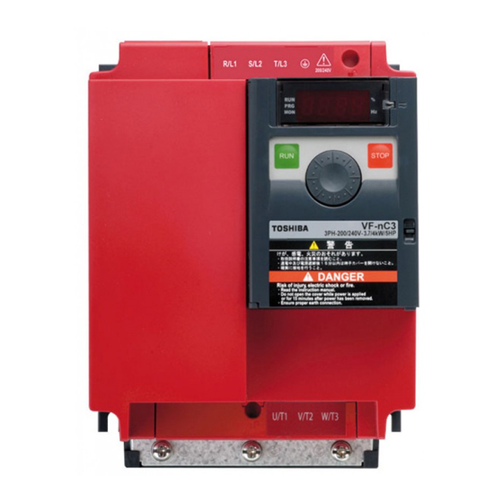
E6581595 Names and functions 1.3.1 Outside view With cover closed Charge lamp Indicate s there is a high voltage still in the inverter. Do not open the terminal block cover when this lamp is lit because it is dangerous. Cover This is the body or terminal block cover. - Page 16 E6581595 Example of the label [Opening the cover] l 14 About the monitor display The LED on the operation panel uses the following symbols to indicate parameters and operations. LED display (numbers) LED display (letters)
- Page 17 E6581595 Warning Never touch the internal terminals in the upper right while the front cover is open. There is a risk of shock because it carries a high voltage. Prohibited [With cover open] RUN lamp % lamp Lit when a frequency is Dispalyed numbers are not output with the ON percents.
- Page 18 E6581595 1.3.2 Opening the terminal cover Caution When removing and installing the terminal cover with a screwdriver, be sure not to scratch your hand as this results in injury. Pressing too hard on the screwdriver may scratch the inverter. Mandatory ...
- Page 19 E6581595 (2) Removing the upper terminal (input terminal) block cover Insert a screwdriver or other thin object into the Press in on the screwdriver. hole indicated with the mark. While pressing on the screwdriver, rotate the Pull the terminal cover up at an angle. terminal cover upward to remove it.
- Page 20 E6581595 1.3.3 Power circuit and control circuit terminal boards 1) Power circuit terminal board In case of the crimp-style terminal, cover the crimp-style terminal with insulated tube, or use the crimp- style terminal with insulation sleeve. Refer to section 2.3.1 for details about terminal functions. Crimp-style terminal NOTE) Screw size Tightening torque...
- Page 21 E6581595 VFNC3-2015 2037P R/L1 S/L2 T/L3 M4 screw Grounding terminal Shorting-bar Short-circuit cover M4 screw PA/+ PC/- U/T1 V/T2 W/T3 Grounding terminal Grounding terminal Grounding terminal M4 screw: 2015, 2202 (M5 screw) M4 screw: 2015, 2202 M5 screw: 2037 M5 screw: 2037 EMC plate for installation (Note 1)
- Page 22 E6581595 VFNC3S-1007P,2015PL,2022PL Grounding terminal Grounding capacitor switch R/L1 S/L2/N (2015, 2022 PL only) M4 screw Short-circuit cover Shorting-bar M4 screw PA/+ PC/- U/T1 V/T2 W/T3 Grounding Grounding terminal Grounding terminal terminal (M4 screw) (M4 screw) (M5 screw) EMC plate for installation (Note 1) * Bend the clips on the wiring port of the terminal cover to connect the PO, PA/+, and PC/- terminals.
- Page 23 E6581595 3) Control circuit terminal board The control circuit terminal board is common to all equipment. FLA FLB FLC CC VI P5 FM RS485 connector OUT NO CC S2 P24 Recommended Stripping length: 6 (mm) Screw size tightening torque Screwdriver: Small-sized flat-blade screwdriver Optional connector 0.5 Nm (Blade thickness: 0.5 mm, blade width: 3.5 mm)
-
Page 24: Notes On The Application
E6581595 Notes on the application 1.4.1 Motors When the VF-nC3 and the motor are used in conjunction, pay attention to the following items. Caution Use an inverter that conforms to the specifications of power supply and three-phase induction motor being operated. If the inverter being used does not conform to those specifications, not only will the three-phase induction motor not rotate correctly, but it may cause serious accidents through overheating Mandatory and fire. - Page 25 E6581595 Low loads and low inertia loads The motor may demonstrate instability such as abnormal vibrations or overcurrent trips at light loads of 5% or under of the load percentage, or when the load's inertia moment is extremely small. If that happens reduce the carrier frequency.
- Page 26 E6581595 Motors with a brake When motors with a brake are directly connected to the inverter's output, the brake cannot be released at startup because of low voltage. Wire the brake circuit separately from the main circuit. 3-phase FLB FLC S2 (ST) NO CC 3-phase power...
- Page 27 E6581595 Power factor correction capacitor Power factor correction capacitors cannot be installed on the output side of the inverter. When a motor is run that has a power factor correction capacitor attached to it, remove the capacitors. This can cause inverter malfunction and capacitor destruction.
- Page 28 E6581595 Disposal Refer to chapter 16. 1.4.3 What to do about the leakage current Caution Current may leak through the inverter's input/output wires because of insufficient electrostatic capacity on the motor with bad effects on peripheral equipment. The leakage current’s value is affected by the carrier frequency and the length of the input/output wires. Mandatory Test and adopt the following remedies against leak current.
- Page 29 E6581595 Remedies: 1. If there is no radio-frequency interference or similar problem, detach the built-in noise filter capacitor, using the grounding capacitor disconnecting switch. (Refer to section 1.3.3-2)) 2. Reduce : PWM carrier frequency. However the motor magnetic noise is increased. (Refer to section 6.11) 3.
- Page 30 E6581595 CT and ammeter If a CT and ammeter are connected externally to detect inverter output current, the leak current's high frequency component may destroy the ammeter. If the wires are more than 50 meters long, it will be easy for the high frequency component to pass through the externally connected CT and be superimposed on and burn the ammeter with models having motors of low rated current (several A (ampere) or less), because the leakage current will increase in proportion to the motor's rated current.
-
Page 31: Instruction Manual
E6581595 1.4.4 Installation Installation environment The VF-nC3 Inverter is an electronic control instrument. Take full consideration to installing it in the proper operating environment. Warning Do not place any inflammable substances near the VF-nC3 Inverter. If an accident occurs in which flame is emitted, this could lead to fire. ... - Page 32 If the VF-nC3 Inverter is installed in a location that is subject to vibration, anti-vibration measures are required. Please consult with Toshiba about these measures. If the VF-nC3 Inverter is installed near any of the equipment listed below, provide measures to insure against errors in operation.
- Page 33 Warning Do not install or operate the inverter if it is damaged or any component is missing. This can result in electric shock or fire. Contact your Toshiba distributor for repairs. Prohibited Mount the inverter on a metal plate.
- Page 34 E6581595 The space shown in the diagram is the minimum allowable space. Because air cooled equipment has cooling fans built in on the top or bottom surfaces, make the space on top and bottom as large as possible to allow for air passage.
- Page 35 E6581595 Panel designing taking into consideration the effects of noise The inverter generates high frequency noise. When designing the control panel setup, consideration must be given to that noise. Examples of measures are given below. Wire so that the main circuit wires and the control circuit wires are separated. Do not place them in the same conduit, do not run them parallel, and do not bundle them.
- Page 36 E6581595 Installing more than one unit in a cabinet If you are installing two or more inverters in one cabinet, pay attention to the following. Inverters may be installed side by side with each other with no space left between them. ...
-
Page 37: Connection
2. Connection Warning Never disassemble, modify or repair. This can result in electric shock, fire and injury. Call your Toshiba distributor for repairs. Disassembly prohibited Don't stick your fingers into openings such as cable wiring hole and cooling fan covers. - Page 38 E6581595 Warning Ground must be connected securely. If the ground is not securely connected, it could lead to electric shock or fire when a malfunction or current leak occurs. Be Grounded Caution Do not attach devices with built-in capacitors (such as noise filters or surge absorber) to the output (motor side) terminal.
-
Page 39: Standard Connections
E6581595 Standard connections Warning Do not connect input power to the output (motor side) terminals (U/T1, V/T2, W/T3). Connecting input power to the output could destroy the inverter or cause a fire. Do not insert a resistor between DC terminals (between PA/+ and PC/-, or between PO and PC/-). It could cause a fire. -
Page 40: Standard Connection Diagram
E6581595 2.2.1 Standard connection diagram 1 This diagram shows a standard wiring of the main circuit. Standard connection diagram - SINK (Negative) (common:CC) DC reactor (DCL) *2 , *5 (option) PA/+ PC/- Main circuit power supply Motor MCCB U/T1 R/L1 3ph-240V class: three-phase 200-240V S/L2 V/T2... - Page 41 E6581595 2.2.2 Standard connection diagram 2 Standard connection diagram - SOURCE (Positive) (common:P24) DC reactor (DCL) *2 , *5 (option) PA/+ Main circuit power supply Motor MCCB U/T1 R/L1 3ph-240V class: three-phase 200-240V S/L2 Noise V/T2 -50/60Hz Power circuit filter T/L3 W/T3 1ph-240V class: single-phase 200-240V...
-
Page 42: Description Of Terminals
E6581595 Description of terminals 2.3.1 Power circuit terminals This diagram shows an example of wiring of the main circuit. Use options if necessary. Power supply and motor connections Power supply No-fuse Power lines are connected +0 breaker ,S/L and T/L VF-nC3 Motor lines are connected to ,V/T... - Page 43 E6581595 Power circuit Terminal symbol Terminal function Grounding terminal for connecting inverter. There are 4 terminals in total. (1 terminal on upper side, 3 terminals on down side) 240V class: three-phase 200 to 240V-50/60Hz single-phase 200 to 240V-50/60Hz R/L1,S/L2,T/L3 120V class: single-phase 100 to 120V-50/60Hz * Single-phase input: R/L1 and S/L2/N terminals Connect to a (three-phase induction) motor.
- Page 44 E6581595 Terminal Input / Electrical Function Inverter internal circuits symbol output specifications 5Vdc Output Analog power supply output (permissible load current: 10mA) Multifunction programmable analog input. Factory default setting: 0-10Vdc (1/1000 resolution) and 0-60Hz (0-50Hz) frequency input. The function can be changed to 0-20mAdc (4-20mA) current input by parameter 5V/10Vdc ...
- Page 45 E6581595 Terminal Input / Electrical Function Inverter internal circuits symbol output specifications Multifunction programmable open Open collector output collector output. Standard default setting 24Vdc-100mA detect and output low speed signal. Multifunction output terminals to which To output pulse two different functions can be assigned. trains, The NO terminal is an isoelectric output a current of 10mA...
- Page 46 E6581595 Connection of SINK (Negative) logic/SOURCE (Positive) logic Current flowing out turns control input terminals on. These are called sink logic terminals. The general used method in Europe is source logic in which current flowing into the input terminal turns it Sink logic is sometimes referred to as negative logic, and source logic is referred to as positive logic.
- Page 47 E6581595 <Examples of connections when an external power supply is used> f127=200 f127=100 Sink (Negative) logic Source (Positive) logic Input Input Common Output Output (f127=200) (f127=100) Note 4) Common Output Output Common Input Input Common Programmable Programmable Inverter Inverter controller controller Note 4) Be sure to connect 0V of external power supply and CC terminal of the inverter.
- Page 48 E6581595 Selecting the functions of the VI terminal between analog input and logic input The functions of the VI terminal can be selected between analog input and logic input by changing parameter settings (). (Factory default setting: Analog input 0-10V) Be sure to connect a resistor between P24 and VI terminals in case of sink logic, between VI and CC terminals in case of source logic.
-
Page 49: Operations
If the inverter begins to emit smoke or an unusual odor, or unusual sounds, immediately turn power off. If the equipment is continued in operation in such a state, the result may be fire. Contact your Toshiba distributor for repairs. -
Page 50: How To Set The Setup Menu
E6581595 How to Set the Setup Menu Warning If incorrect setting, the drive may has some damage or unexpected movement. Be sure to set the setup parameter correctly. Mandatory action Set the setup menu according to the logic for control input signals used and the base frequency of the motor connected. - Page 51 E6581595 Values set by each setup parameter Title Function (Mainly in (Mainly in North (Mainly in Asia, (Mainly in Japan) Europe) America) Oceania) Maximum 50.0(Hz) 60.0(Hz) 50.0(Hz) 80.0(Hz) frequency Frequency / 50.0(Hz) 60.0(Hz) 50.0(Hz) / settings 60.0(Hz)
-
Page 52: Simplified Operation Of The Vf-Nc3
E6581595 Simplified Operation of the VF-nC3 Operation command and Operation frequency command are necessary to operate the inverter. Operation method and operation frequency setting can be selected from the following. At default setting, the inverter runs and stops with RUN/STOP key on the panel keypad, and frequency can be set with the setting dial. - Page 53 E6581595 3.2.1 How to run and stop [Example of a setting procedure] Panel operation LED display Operation Displays the output frequency (operation stopped). (When standard monitor display selection = [Output frequency]) MODE Displays the first basic parameter [History ()]. ...
- Page 54 E6581595 (3) Coast stop Motor Coast stop speed Assign parameters as described below in case of Coast stop. Inverter will display off at Coast stop. 1) Assign "6 (ST)" to an input terminal. Set parameter F-CC =. Open the ST-CC for coast stop(see the status described on the right).
- Page 55 E6581595 Example of operating from the panel (=: save even if power is off) Panel operation LED display Operation Displays the output frequency. (When standard monitor display selection = [Output frequency]) Set the frequency command value. The frequency will be saved even if the power is turned off in this ...
-
Page 56: Frequency Setting
E6581595 (2) Setting of frequency using external signals to terminal block (=) Frequency setting Setting the frequency using external potentiometer ★Potentiometer Setting frequency using the potentiometer (1-10k, 1/4W) Refer to section 6.5.2 for detailed adjustment. : Setting frequency 50 or 60Hz using potentiometer Frequency Note) Set parameter =. -
Page 57: How To Operate The Vf-Nc3
E6581595 How to operate the VF-nC3 Overview of how to operate the inverter with simple examples. Operation Command: Panel Operation Ex.1 Frequency Command: Setting Dial 1 Wiring PA/+ PC/- Motor U/T1 R/L1 V/T2 S/L2 W/T3 T/L3 Operation panel Parameter setting (default setting) Title Function Programmed value... - Page 58 E6581595 Operation Command: Panel Operation Ex.2 Frequency Command: Setting Dial 2 Wiring PA/+ PC/- Motor U/T1 R/L1 V/T2 S/L2 W/T3 T/L3 Operation panel Parameter setting Title Function Programmed value Command mode selection Frequency setting mode selection Operation Run/stop: Press the keys on the panel.
- Page 59 E6581595 Operation Command: External Signal Ex.3 Frequency Command: Setting Dial Wiring PA/+ PC/- Motor MCCB U/T1 R/L1 S/L2 V/T2 W/T3 T/L3 Forward Operation panel signal Reverse signal Common Parameter setting Title Function Programmed value Command mode selection Frequency setting mode selection 1 or 2 ...
- Page 60 E6581595 Operation Command: External Signal Ex.4 Frequency Command: External Analog Signal Wiring PA/+ PC/- Motor MCCB R/L1 U/T1 S/L2 V/T2 T/L3 W/T3 Forward signal Reverse signal Common Current signal: 420mA Voltage signal: 010V / 05V External potentiometer (Otherwise, input voltage signal between the terminals VI-CC.) Parameter setting Title Function...
-
Page 61: Meter Setting And Adjustment
E6581595 Meter setting and adjustment : Meter selection : Meter adjustment gain Function Output of 0 - 1mAdc, 0 (4) - 20mAdc, 0 - 10vdc can be selected for the output signal from the FM terminal, depending no the setting. Adjust the scale at . Use an ammeter with a full-scale 0 - 1mAdc meter. - Page 62 E6581595 Resolution All FM terminals have a maximum of 1/255. Example of 4-20mA output adjustment (Refer to section 6.17.2 for details) =1, =0 =1, =20 (mA) (mA) Output Output currrent currrent f692 100% 100% Internal calculated value Internal calculated value Note 1) When using the FM terminal for current output, be sure that the external load resistance is less than 750Ω.
- Page 63 E6581595 [Example of how to adjustment the FM terminal frequency meter] Use the meter's adjustment screw to pre-adjust zero-point. Operation panel action LED display Operation Displays the output frequency. . (When standard monitor display selection = [Output frequency]) The first basic parameter “” (history function) is displayed. MODE ...
-
Page 64: Setting The Electronic Thermal
E6581595 Setting the electronic thermal : Motor electronic-thermal protection level 1 : Electronic-thermal protection characteristic selection 3 : Motor electronic-thermal protection level 2 : Motor 150% overload detection time : Electronic-thermal memory Function This parameter allows selection of the appropriate electronic thermal protection characteristics according to the particular rating and characteristics of the motor. - Page 65 E6581595 1) Setting the electronic thermal protection characteristics selection and motor electronic thermal protection level 1 , 2 The electronic thermal protection characteristics selection is used to enable or disable the motor overload trip function () and the overload stall function. While the inverter overload trip () will be in constant detect operation, the motor overload trip () can be selected using the parameter ...
- Page 66 E6581595 Output current reduction factor [%]/[A] ×1.0 ×0.6 30Hz Output frequency (Hz) Note: The motor overload protection start level is fixed at 30Hz. [Example of setting: When the VFNC3-2007P is running with a 0.4kW motor having 2A rated current] Operation LED display Operation panel action...
- Page 67 E6581595 Setting of motor electronic thermal protection level 1 (Same as f173) If the capacity of the motor is smaller than the capacity of the inverter, or the rated current of the motor is smaller than the rated current of the inverter, adjust the electronic thermal protection level 1 so that it fits the motor's rated current.
- Page 68 E6581595 Note1 : At extremely low speeds of lower than 1 Hz, an overload trip (ol3) occurs in a short period of time to protect the inverter. Note2 : At over 150%, an overload trip (ol1 ) occurs in a short period of time to protect the inverter. 4) Electronic thermal memory f632 When the power is OFF, it is possible to reset or maintain the overload totaling level.
-
Page 69: Preset-Speed Operation (Speeds In 15 Steps
E6581595 Preset-speed operation (speeds in 15 steps) - : Preset-speed frequency 1-7 - : Preset-speed frequency 8-15 Function A maximum of 15 speed steps can be selected just by switching an external logic signal. Multi-speed frequencies can be programmed anywhere from the lower limit frequency ... - Page 70 E6581595 Preset-speed logic input signal example: (sink/source switching) =: With sink settings O: ON -: OFF (Speed commands other than preset-speed commands are valid when all are OFF) Preset-speed Terminal S1-CC S2-CC ...
- Page 71 E6581595 3) Using other speed commands with preset-speed command 1: Panel keypad (including extension panel), Command mode selection 0: Terminal board 2: RS485 communication 1: Setting dial 1 0: Terminal board 0: Terminal block (press in center to 1: Setting dial Frequency setting save) 3: RS485...
-
Page 72: Setting Parameters
E6581595 4. Setting parameters Setting and Display Modes The VF-nC3 has the following three display modes. Standard monitor mode The standard inverter mode. This mode is enabled when inverter power goes on. This mode is for monitoring the output frequency and setting the frequency reference value. If also displays information about status alarms during running and trips. - Page 73 E6581595 Status monitor mode The mode for monitoring all inverter status. Allows monitoring of set frequencies, output current/voltage and terminal information. Refer to chapter 8. The inverter can be moved through each of the modes by pressing the MODE key. ...
-
Page 74: How To Set Parameters
E6581595 How to set parameters There are two types of setting monitor modes: Easy mode and Standard setting mode. The mode active when power is turned on can be selected at (EASY key mode selection), and the mode can be switched by the EASY key. Note, however, that the switching method differs when only the Easy mode is selected. - Page 75 E6581595 Standard setting mode : The mode changes to the Standard setting mode when the EASY key is pressed and "" is displayed. Both basic and extended all parameters are displayed. Basic parameters : This parameter is a basic parameter for the operation of the inverter.
- Page 76 E6581595 4.2.1 Settings in the Easy setting mode The inverter enters this mode by pressing the MODE key when the Easy setting mode is selected Easy setting mode (Default registered parameters) When you are unsure of something Title Function during operation: Command mode selection ...
- Page 77 E6581595 4.2.2 Settings in the Standard setting mode The inverter enters this mode by pressing the MODE key when the Standard setting mode is selected. How to set basic parameters When you are unsure of something (1) Selects parameter to be changed. (Turn the setting dial.) during operation: You can return to the Standard monitor (2) Reads the programmed parameter setting.
-
Page 78: Functions Useful In Searching For A Parameter Or Changing A Parameter Setting
E6581595 How to set extended parameters Each extended parameter is composed of an ""suffixed with a 3-digit figure, so first select and read out the heading of the parameter you want "" to "". ("": Parameter starting point is 100, "": Parameter starting point is 800.) (5) Select the title of the parameter you want to change. - Page 79 E6581595 Reset parameters to default settings Use the parameter to reset all parameters back to their default settings. To use this function, set parameter = or . Refer to section 4.3.2 for details. Call saved customer settings Customer settings can be batch-saved and batch-called.
- Page 80 E6581595 How to search and reprogram parameters Panel operation LED display Operation Displays the output frequency (operation stopped). (When standard monitor display selection = [Output frequency]) MODE Displays the first basic parameter "History function ()." Turn the setting dial, and select . ...
- Page 81 E6581595 4.3.2 Return to default settings : Default setting Function It is possible to return groups of parameters to their defaults, clear run times, and record/recall set parameters. [Parameter setting] Title Function Adjustment range Default setting 0: - 1: 50Hz default setting 2: 60Hz default setting 3: Default setting 1 (Initialization)
- Page 82 E6581595 Default setting 1 ( = ) Setting to will return parameters to the standard values that were programmed at the factory. When is set, is displayed for a short time after the settings are configured, and then disappears.
-
Page 83: Checking The Region Settings Selection
E6581595 Checking the region settings selection : Checking the region setting Function The region selected on the setup menu can be checked. Also, the setup menu can be started to change to a different region. [Parameter setting] Title Function Adjustment range Default setting... -
Page 84: Easy Key Function
E6581595 EASY key function : EASY key mode selection - : Easy setting mode parameter 1 to 24 • Function It is possible to switch between standard mode and easy setting mode using the EASY key. Up to 24 arbitrary parameters can be registered to easy setting mode. [Parameter setting] Title Function... - Page 85 E6581595 [How to select parameters] In easy setting mode, only parameters registered to parameters 1 to 24 are displayed in order of registration. The values of the default settings are shown in the table below. [Parameter setting] Title Function Adjustment range Default setting -...
-
Page 86: Main Parameters
E6581595 5. Main parameters Before you operate the inverter, the parameters that you must first program are the basic parameters. Refer to section 11 tables of basic parameters. Searching for changes using the history function () : History function History function (): Automatically searches for 5 latest parameters that are programmed with values different from the standard default setting and displays them in the . -
Page 87: Setting A Parameter Using The Guidance Function
E6581595 Parameter display MODE Press the MODE key to return to the parameter setting mode “.” MODE After that you can press the MODE key to return to the status monitor mode or the standard monitor mode (display of output ... - Page 88 E6581595 How to use the guidance function Here are the steps to follow to set parameters, using the guidance function. (When the basic setting guidance (auf) is set to 1) Operation panel LED display Operation action Displays the output frequency (operation stopped). ...
- Page 89 E6581595 Table of parameters that can be changed using the guidance function Preset-speed setting Analog input operation Motor 2 switching operation Motor constant setting guidance guidance guidance guidance auf=2 auf=3 auf=4 auf=5 ...
-
Page 90: Setting Acceleration/Deceleration Time
E6581595 Setting acceleration/deceleration time 5.3.1 Automatic acceleration/deceleration :Automatic acceleration/deceleration Function This automatically adjusts acceleration and deceleration time in line with load. Refer to section 5.3.2 for setting acceleration/ deceleration time manually. = * Adjusts the acceleration/deceleration time automatically within the range of 1/8 to 8 times as long as the time set with the ... - Page 91 E6581595 [Methods of setting automatic acceleration/deceleration] Operation panel LED display Operation action Displays the output frequency. (When standard monitor display selection = [Output frequency]) MODE The first basic parameter “” (history function) is displayed. Turn the setting dial to the right to change the parameter to . ...
-
Page 92: Increasing Starting Torque
E6581595 If the programmed value is shorter than the optimum acceleration/deceleration time determined by load conditions, overcurrent stall or overvoltage stall function may make the acceleration/deceleration time longer than the programmed time. If an even shorter acceleration/deceleration time is programmed, there may be an overcurrent trip or overvoltage trip for inverter protection. - Page 93 E6581595 Note 1: The same characteristic can be obtained by setting the V/F control mode selection parameter to (automatic torque boost control) and the auto-tuning parameter to (auto-tuning). Refer to section 6.14 Note 2: Setting to automatically programs to . 2) When using vector control (increasing starting torque and high-precision operations) ...
- Page 94 E6581595 When vector control cannot be programmed First read the precautions about vector control in section 5.11-6). 1) If the desired torque cannot be obtained ⇒ Refer to section 6.14 selection 2 2) If auto-tuning error "" appears ⇒ Refer to section 6.14 selection 3 ...
-
Page 95: Selection Of Operation Mode
E6581595 Selection of operation mode : Command mode selection : Frequency setting mode selection Function These parameters are used to specify which input device (panel keypad, terminal block, or RS485 communication) takes priority in entering an operation stop command or frequency setting mode (terminal VI, setting dial, RS485 communication, or UP/DOWN from external logic). - Page 96 E6581595 [Programmed value] A frequency command is set by means of external signals (VI terminal: 0 - 5/ : Terminal board VI 0 - 10 Vdc, or 0 (4) - 20 mAdc). Refer to section 3.2.2 and 7.3 Frequencies are set by rotating the setting dial on the inverter. Press the center of the setting dial to save the frequency setting value.
- Page 97 E6581595 Example of run and frequency command switching Command mode and frequency setting mode switching Command mode selection With extension panel Terminal block RS485 communication (option) RKP007Z active (CMTB) priority clear Input terminal (SCLC) function Input terminal function :108/109 :48/49 Terminal block...
-
Page 98: Meter Setting And Adjustment
E6581595 Meter setting and adjustment : Meter selection : Meter adjustment gain Refer to section 3.4 for details. Forward/reverse run selection (Panel keypad) : Forward/reverse run selection (Panel keypad) Function Program the direction of rotation of the motor when the running and stopping are made using the RUN key and STOP key on the operation panel. -
Page 99: Maximum Frequency
E6581595 The inverter was factory-configured by default so that shorting terminals F-CC and terminals R-CC simultaneously would cause the motor to slow down to a stop. Using the parameter , however, you can select between forward run and reverse run. Maximum frequency : Maximum frequency ... -
Page 100: Upper Limit And Lower Limit Frequencies
E6581595 Upper limit and lower limit frequencies : Upper limit frequency : Lower limit frequency Function Programs the lower limit frequency that determines the lower limit of the output frequency and the upper limit frequency that determines the upper limit of that frequency. Lower limit Upper limit Command frequency (Hz) -
Page 101: Base Frequency
E6581595 5.10 Base frequency : Base frequency 1 : Base frequency voltage 1 Function Set the base frequency and the base frequency voltage in conformance with load specifications or the base frequency. Note: This is an important parameter that determines the constant torque control area. Base frequency voltage ... -
Page 102: Selecting Control Mode
E6581595 5.11 Selecting control mode : V/F control mode selection Function With VF-nC3, the V/F controls shown below can be selected. V/F constant Variable torque Automatic torque boost control *1 Vector control *1 Energy saving *1 (*1) Parameter setting macro torque boost: ... - Page 103 E6581595 Caution: When the V/F control mode selection is set to : Automatic torque boost control, : Vector control, or : Energy-saving, be sure to set the following parameters according to the motor's name plate. : Base frequency 1 (rated frequency) : Base frequency voltage 1 (rated voltage) ...
- Page 104 Motor constant must be set If the motor you are using is a 4P Toshiba standard motor and if it has the same capacity as the inverter, there is basically no need to set the motor constant. In any other case, set the following parameters according to the motor's name plate.
- Page 105 Motor constant must be set If the motor you are using is a 4P Toshiba standard motor and if it has the same capacity as the inverter, there is basically no need to set the motor constant. In any other case, set the following parameters according to the motor's name plate.
-
Page 106: Manual Torque Boost - Increasing Torque Boost At Low Speeds
E6581595 5) Use a motor that has 2-8 P. 6) Always operate the motor in single operation (one inverter to one motor). Sensorless vector control cannot be used when one inverter is operated with more than one motor. When using a combination of several motors, set the V/F constant (=). 7) The maximum length of wires between the inverter and motor is 30 meters. -
Page 107: Setting The Electronic Thermal
E6581595 5.13 Setting the electronic thermal t : Motor electronic-thermal protection level 1 o : Electronic thermal protection characteristic selection Refer to section 3.5 for details 5.14 Preset-speed operation (speeds in 15 steps) s - : Preset-speed frequency 1-7 Refer to section 3.6 for details. -
Page 108: Other Parameters
E6581595 6. Other parameters Extended parameters are provided for sophisticated operation, fine adjustment and other special purposes. Modify parameter settings as required. Refer to section 11 tables of extended parameters. Input/output parameters 6.1.1 Low-speed signal : Low-speed signal output frequency ... - Page 109 E6581595 An example of the connection of the open collector An example of the connection of the relay OUT terminal (sink logic) output terminals +24V +24V Output terminal setting Default outputs low-speed signal (ON signal) to OUT terminal. This setting must be changed to invert the polarity of the signal.
- Page 110 E6581595 Output frequency [Hz] Designated frequency Setting frequency Designated frequency Time [s] Output frequency attainment signal : OUT-NO terminals Inversion of output frequency attainment signal 6.1.3 Output of set frequency speed reach signal : Speed reach setting frequency ...
-
Page 111: Input Signal Selection
E6581595 If the detection band value + the set frequency is less than the designated frequency Output frequency [Hz] + - Time [s] Set frequency attainment signal : OUT-NO terminals Inversion of set frequency attainment signal Input signal selection 6.2.1 Priority selection (Both F and R are ON) - Page 112 E6581595 (1) [ = (Reverse)]: If an F command and an R command are entered simultaneously, the motor will run in the reverse direction. Output frequency [Hz] Setting frequency Forward run Time [s] Reverse run Setting frequency Forward run command Reverse run command (2) [...
- Page 113 E6581595 6.2.2 Changing the functions of VI terminal : Analog/logic input selection (VI terminal) Function This parameter allows you to choose between analog input and logic input for the VI terminal. [Parameter setting] Title Function Adjustment range Default setting 0: Voltage signal input (0 - 10V) Analog/logic input 1: Current signal input (4 - 20mA)
-
Page 114: Terminal Function Selection
E6581595 Terminal function selection 6.3.1 Changing control logic switching : Sink/source switching Function Logic input terminal sink logic (minus common)/source logic (plus common) and using an external power supply are switched. [Parameter setting] Title Function Adjustment range Default setting 0: Sink(Internal power supply), 100: Source, ... -
Page 115: Modifying Input Terminal Functions
E6581595 Explanation of the coast stop function Coast stop When ST (Standby) is OFF, coast stops. Motor speed The default setting for ST (Standby) is ON, change the following settings. (no function) F-CC Assign open input terminal 6: ST (Standby). Coast stops if terminal set for ST (Standby) is set to ST-CC OFF. -
Page 116: Basic Parameters 2
E6581595 Basic parameters 2 6.4.1 Switching motor characteristics via terminal input : Base frequency 2 : Base frequency voltage 2 : Torque boost value 2 : Motor electronic-thermal protection level 2 : Stall prevention level 2 ... - Page 117 E6581595 Setting of switching terminals To switch to motor 2, assign the following functions to a terminal not being used. It is also possible to switch to acceleration/deceleration 2 (AD2). Refer to section 6.15.1 for details. It is possible to set 3 functions for terminal F and R, and 2 functions for terminal S1 and S2. Input terminal function number Parameters changed from applicable parameters and default standards...
-
Page 118: Setting Frequency Command
E6581595 Setting frequency command 6.5.1 Switching frequency command : Frequency setting mode selection - : Input terminal selection 1A, 2A, 3A, 4A, 5 - : Input terminal selection 1B, 2B, 3B, 4B, 1C, 2C Function Frequency command can be changed according to the terminal block input. -
Page 119: Setting Frequency Command Characteristics
E6581595 6.5.2 Setting frequency command characteristics : Analog/logic input selection (VI terminal) : VI Input point 1 setting : VI Input point 1 frequency : VI Input point 2 setting : VI Input point 2 frequency ... - Page 120 E6581595 0-10Vdc voltage input adjustment VI terminal Point settings adjust the frequency command for the 50/60 (Hz) voltage input. Gradient and bias can be set easily. 0 ( Hz) (Voltage input: 0-10V) 0 (%) 100 (%) 10V voltage signal Frequency commnd...
- Page 121 E6581595 6.5.3 Setting of frequency with the input from an external logic : External logic input - UP response time : External logic input - UP frequency steps : External logic input - DOWN response time : External logic input - DOWN frequency steps ...
- Page 122 E6581595 Adjustment with continuous signals (Operation example 1) Set parameters as follows to adjust the output frequency up or down in proportion to the frequency adjustment signal input time: Panel frequency incremental gradient = / setting time Panel frequency decremental gradient = / setting time Set parameters as follows to adjust the output frequency up or down almost in synchronization with the adjustment by the panel frequency command: ...
- Page 123 E6581595 <<Sample sequence diagram 2: Adjustment with pulse signals>> Forward / reverse command UP signal DOWN signal Set frequency clearing signal Upper limit frequency Command frequency(Hz) (The dotted lines represent effective output frequencies) If two signals are impressed simultaneously ...
-
Page 124: Fine Adjustment Of Frequency Setting Signal
E6581595 6.5.4 Fine adjustment of frequency setting signal : VI voltage bias : VI voltage gain Function These parameters are used to fine adjust the relation between the frequency setting signal input through the analog input terminal VI and the output frequency. Use these parameters to make fine adjustments after making rough adjustments using the parameters f201 to f204. -
Page 125: Operation Frequency
E6581595 Operation frequency 6.6.1 Starting frequency : Starting frequency Function The frequency set with is put out as soon as operation is started. Use the parameter when a delay in response of starting torque according to the acceleration/deceleration time is probably affecting operation. -
Page 126: Dc Braking
E6581595 DC braking : DC braking starting frequency : DC braking current : DC braking time Function A large braking torque can be obtained by applying a direct current to the motor. These parameters set the direct current to be applied to the motor, the application time and the starting frequency. [Parameter setting] Title Function... -
Page 127: Time Limit For Lower-Limit Frequency Operation
E6581595 Time limit for lower-limit frequency operation : Time limit for lower-limit frequency operation : Hysteresis for lower-limit frequency operation Function If operation is carried out continuously at a frequency below the lower-limit frequency () for the period of time set with , the inverter will automatically slow down the motor to a stop. -
Page 128: Jump Frequency - Avoiding Frequency Resonance
E6581595 Jump frequency - Avoiding frequency resonance : Jump frequency : Jumping width Function Resonance due to the natural frequency of the mechanical system can be avoided by jumping the resonant frequency during operation. During jumping, hysteresis characteristics with respect to the jump frequency are given to the motor. -
Page 129: Pwm Carrier Frequency
E6581595 6.11 PWM carrier frequency : PWM carrier frequency : Random mode : Carrier frequency control mode selection Function These parameters are effective in preventing the magnetic noise reduction from the motor, noise reduction, the measure against resonance with load machine, etc. 1) When you reduce the magnetic noise from the motor, increase the f300: PWM carrier frequency. - Page 130 E6581595 Load reduction (current reduction) by carrier frequency and ambient temperature [Three phase 200 V class] Carrier frequency Ambient VFNC3 temperature 2 - 4 kHz 5 - 12 kHz 13 - 16 kHz 2001P 0.7 A 0.7 A 0.7 A 60C or less 1.4 A 1.4 A...
-
Page 131: Trip-Less Intensification
E6581595 6.12 Trip-less intensification 6.12.1 Auto-restart (Restart of coasting motor) : Auto-restart control selection Caution Stand clear of motors and mechanical equipment If the motor stops due to a momentary power failure, the equipment will start suddenly when power is restored. - Page 132 E6581595 2) Restarting motor during coasting (Motor speed search function) Motor speed Forward / reverse ST-CC Setting to or : This function operates after the ST-CC terminal connection has been opened first and then connected again. Note 1: The terminal function ST needs to be assigned to an input terminal, using the parameters to .
- Page 133 E6581595 6.12.2 Regenerative power ride-through control (Deceleration stop) : Regenerative power ride-through control (Deceleration stop) Function 1) Regenerative power ride-through control: When momentary power failure occurs during operation, this function makes operation continue using the regeneration energy from a motor. 2) Deceleration stop during power failure: When momentary power failure occurs during operation, this function stops the motor quickly and compulsorily using the regeneration energy from the motor.
- Page 134 E6581595 [If momentary power failure occurs] Input voltage DC Voltage Motor speed Normal acceleration Note 5: If momentary power failure occurs during deceleration stop, power ride-through control will not be performed. An example of setting when f302=2 Input voltage Motor speed Time Deceleration stop...
-
Page 135: Retry Function
E6581595 6.12.3 Retry function : Retry selection (number of times) Caution Do not go near the motor in alarm-stop status when the retry function is selected. The motor may suddenly restart, which could result in injury. Take measures for safety, e.g. attach a cover to the motor, to prevent accidents if the motor suddenly Mandatory restarts. -
Page 136: Avoiding Overvoltage Tripping
E6581595 6.12.4 Avoiding overvoltage tripping : Overvoltage limit operation Function These parameters are used to keep the output frequency constant or increase it to prevent overvoltage tripping in case the voltage in the DC section rises during deceleration or varying speed operation. - Page 137 E6581595 6.12.5 Output voltage adjustment/Supply voltage correction : Base frequency voltage 1 : Supply voltage correction (output voltage limitation) Function Supply voltage correction: Prevent torque decline during low-speed operation. Maintains a constant V/F ratio, even when the input voltage fluctuates. Output voltage limitation: Limits the voltage to prevent outputting the voltage over base frequency voltage (vlv).
- Page 138 E6581595 [: No voltage compensation/output voltage limited] [: Voltage compensation/output voltage limited] Input voltage High Input voltage Input voltage High Output frequency Output frequency * The above applies when V/F control mode selection parameter is set to "0" or "1". ...
-
Page 139: Pid Control
E6581595 6.12.6 Reverse-run prohibition : Reverse-run prohibition Function This function prevents the motor from running in the forward or reverse direction when it receives the wrong operation signal. [Parameter setting] Title Function Adjustment range Default setting 0: Forward/reverse run permitted Reverse-run prohibition 1: Reverse run prohibited ... - Page 140 E6581595 1) Example of External connection Inverter Motor R/L1 U/T1 S/L2 V/T2 Pressure Pressure T/L3 W/T3 transmitter transmitter Pump (1) Panel setting ①PID set value setting (1) Panel keypad setting (2) Internal preset-speed Setting dial setting ②Feedback value: Current signal input (4-20mA) Feedback signals (1)DC : 4~20mA (2)DC : 0~10V (3)DC : 0~5V 2) Selecting PID set value and feedback value PID set value (frequency) and feedback value can be combined as follows for the PID control.
- Page 141 E6581595 4) Adjusting the PID control gain level Adjust the PID control gain level according to the PID set value, the feedback value and the object to be controlled. The following parameters are provided for gain adjustment: Title Function Adjustment range Default setting Proportional gain (P) 0.01 - 100.0...
- Page 142 E6581595 (D-gain adjustment parameter) This parameter adjusts the differential gain level during PID control. This gain increases the speed of response to a rapid change in deviation (difference between the PID set value and the feedback value). Note that setting the gain more than necessary may cause fluctuations in output frequency, and thus operation to become unstable.
- Page 143 E6581595 7) PID control forward/reverse characteristic switch PID input characteristics can be reversed. Opposite ×(-1) PID set value Output Original characteristic Feedback value Characteristic selection (parameter or terminal input) When characteristic is reversed according to parameters Set : PID forward/reverse characteristics selection=1 (Reverse). When characteristic is reversed using logic input terminal ...
-
Page 144: Setting Motor Constants
E6581595 6.14 Setting motor constants : Auto-tuning : Motor rated current : Slip frequency gain : Motor no-load current : Automatic torque boost value : Motor rated speed : Motor rated capacity : Load inertia moment ratio To use vector control, automatic torque boost and automatic energy saving, motor constant setting (motor tuning) is required. - Page 145 E6581595 [Selection 2: Setting vector control and auto-tuning independently] Set vector control, automatic torque boost, and energy saving and auto-tuning individually. After setting (V/F control mode selection), auto-tuning occurs. Set the auto-tuning parameter to (Auto-tuning enabled) [Parameter setting] Title Function Adjustment range...
- Page 146 E6581595 Setting procedure Adjust the following parameters: : Set the compensation gain for the slipping of the motor. A higher slip frequency reduces motor slipping correspondingly. After setting , set to adjust in detail. Be careful as inputting a value larger than necessary causes hunting and other unstable operation. : Adjust the primary resistive component of the motor.
-
Page 147: 2Nd Acceleration/Deceleration
E6581595 6.15 2nd acceleration/deceleration 6.15.1 Switching acceleration/deceleration time 1 & 2 :Acceleration time 2 :Deceleration time 2 : Acceleration/deceleration 1 & 2 switching frequency Function Acceleration and deceleration times can be set individually. Select from the following two methods for selecting and switching. - Page 148 E6581595 2) Switching according to terminal (switching acceleration/deceleration time by external terminal) Output frequency [Hz] Time [s] Second acceleration/deceleration selection signal (3) Acceleration at ramp of (1) Acceleration at ramp of deceleration time acceleration time (2) Acceleration at ramp of (4) Acceleration at ramp of acceleration time ...
- Page 149 E6581595 1) Linear acceleration/deceleration Normal acceleration/deceleration Output frequency [Hz] pattern. Max. frequency Normally, this setting can be used. Time [s] 2) S-pattern acceleration/deceleration 1 Select this pattern to accelerate/decelerate the motor rapidly to an output frequency over 60Hz or to minimize the shocks applied during acceleration/deceleration.
-
Page 150: Protection Functions
E6581595 6.16 Protection functions 6.16.1 Setting motor electronic thermal protection : Motor electronic-thermal protection level 1 173 : Motor electronic-thermal protection level 2 : Motor 150% overload detection time : Electronic-thermal memory Function This parameter allows selection of the appropriate electronic thermal protection characteristics according to the particular rating and characteristics of the motor. - Page 151 E6581595 [Parameter setting] Title Function Adjustment range Default setting Stall prevention level 1 10-199 (%) / (A), 200: Disabled Stall prevention level 2 [Display during operation of the stall prevention] During an alarm status, (that is , when there is a current flow in excess of the stall prevention level), the output frequency changes.
-
Page 152: Emergency Stop
E6581595 ■ Flow of operation when = Reset the Completion of reset Normal operation inverter by panel or terminal Occurrence of a operation. The relay trips again. trip If the cause of the ・Display of the cause trip is not ・Failure signal FL Turn power off, eliminated... -
Page 153: Output Phase Failure Detection
E6581595 2) Emergency stopping from the operation panel Emergency stopping from the operation panel is possible by pressing the STOP key on the panel twice while the inverter is not in the panel control mode. (1) Press the STOP key ......"" will blink. (2) Press the STOP key once again .. - Page 154 E6581595 6.16.6 Input phase failure detection : Input phase failure detection selection Function This parameter detects inverter input Phase failure. If the abnormal voltage status of main circuit capacitor persists for few minutes or more, the tripping function and the FL relay will be activated. Trip display is .
- Page 155 E6581595 [Parameter setting] Function Adjustment range Default setting Title Small current detection hysteresis 1-20 (%) 0: Alarm only Small current trip/alarm selection 1: Tripping Small current detection current 0-150 (%) / (A) Small current detection time 0-255 (s) ...
- Page 156 E6581595 [Parameter setting] Function Adjustment range Default setting Title 0: Each time (standard pulse) 1: Only one time after power on Detection of output short-circuit at (standard pulse) start-up 2: Each time (short pulse) 3: Only one time after power on (short pulse) 6.16.9 Over-torque trip ...
-
Page 157: Cooling Fan Control Selection
E6581595 <Example of operation> 1) Output terminal function: 28 (OT) Over-torque detection = (Alarm only) Over-torque signal output less than - Torque (%) Time [sec] When = (tripping), the inverter will trip if over-torque lasts for the period of time set with . - Page 158 E6581595 6.16.11 Cumulative operation time alarm setting : Cumulative operation time alarm setting Function This parameter allows you to set the inverter so that it will put out an alarm signal after a lapse of the cumulative operation time set with . "0.1"...
- Page 159 E6581595 6.16.13 VI analog input break detection : VI analog input break detection level Function The inverter will trip if the VI value remains below the specified value for about 0.3 seconds. In such a case, "" is displayed. =0: Disabled..Not detected.
-
Page 160: Adjustment Parameters
E6581595 6.17 Adjustment parameters 6.17.1 Pulse train output for meters : Logic output/pulse train output selection (OUT) : Pulse train output function selection (OUT) : Maximum numbers of pulse train Function Pulse trains can be sent out through the OUT output terminals. To do so, it is necessary to select a pulse output mode and specify the number of pulses. - Page 161 E6581595 6.17.2 Calibration of analog output : Analog output signal selection : Inclination characteristic of analog output : Analog output bias Function Output signal from the FM terminal can be switched between 0 to 1mAdc output, 0 to 20mAdc output, and 0 to 10Vdc output with the ...
-
Page 162: Operation Panel Parameter
E6581595 6.18 Operation panel parameter 6.18.1 Prohibition of key operations and parameter settings : Parameter write protection selection : Panel frequency setting prohibition (fc) : Local/remote key prohibition of extension panel : Panel operation prohibition (RUN/STOP keys) ... - Page 163 E6581595 Assigning the parameter editing permission (function number 110, 111) to any logic input terminal, parameters can be written regardless of the setting of f700. Note1: f700=2 will be available after reset operation. When protection using a password is necessary, set and remove with the following method. ■...
- Page 164 E6581595 6.18.2 Changing the unit (A/V) from a percentage of current and voltage :Current/voltage unit selection Function These parameters are used to change the unit of monitor display. % A (ampere)/V (volt) Current 100% = Rated current of inverter 100 V class: Input voltage 100% = 100Vac Output voltage 100% = 200Vac 200 V class: Input/output voltage 100% = 200Vac...
- Page 165 E6581595 6.18.3 Displaying the motor or the line speed : Free unit display scale Function The frequency or any other item displayed on the monitor can be converted freely into the rotational speed of the motor, the operating speed of the load, and so on. The value obtained by multiplying the displayed frequency by the -set value will be displayed as follows: Value displayed = Monitor-displayed or parameter-set frequency ...
-
Page 166: Operation Example
E6581595 [Parameter setting] Title Function Adjustment range Default setting 0.00: Disabled (display of frequency) Free unit display scale 0.00 0.01-200.0 The converts the following parameter settings: Free unit Frequency monitor display Output frequency, Frequency command value, PID feedback value, Stator frequency , , , , ... - Page 167 E6581595 6.18.5 Changing the initial display of the panel : Initial panel display selection : Initial extension panel display selection Function This parameter specifies display format while power is ON. Changing the display format while power is ON When the power is ON, the standard monitor mode displays the output frequency (default setting) in the format of ""...
- Page 168 E6581595 6.18.7 Cancel the operation command f719 : Selection of operation command clear Function This parameter allows you to select operation command retained or operation command canceled, when coast stop occurs due to standby terminal function (ST) or coast stop command terminal function(FRR), and when under voltage in main circuit alarm() occurs, during panel operation or RS485 communication operation.
-
Page 169: Communication Function (Rs485
E6581595 6.19 Communication function (RS485) : Baud rate : Block write data 1 : Parity : Block write data 2 : Inverter number : Block read data 1 : Communication time-out time : Block read data 2 ... - Page 170 condition fmod or cmod 2: 1 during operation Selection of communication 0: Toshiba inverter protocol protocol 1: ModbusRTU protocol *1: Disabled ..Indicates that the inverter will not be tripped even if a communication error occurs. *2: Trip ....The inverter trips when a communication time-over occurs.
- Page 171 E6581595 Title Function Adjustment range Default setting 0: No selection 1: Command information Block write data 1 2: - 3: Frequency command value 4: Output data on the terminal board Block write data 2 5: Analog output for communication 0: No selection ...
- Page 172 E6581595 Communication function settings Commands and frequency settings are given priority by communication. (Prioritized by commands from the panel or terminal block.) Thus, command and frequency settings from communication are activated, regardless of the command mode selection () or frequency settings mode selection settings (). However, setting 48: SCLC (switching from communication to local) with input terminal function selection and when inputting from an external device, it is possible to operate at command mode selection () and frequency setting mode selection () settings.
- Page 173 E6581595 Configuration of RS485 connector and wiring Inverter viewed RS485 Name Description from bottom number communication For factory Do not connect (SG) Ground Same phase RXD+/TXD+ reception data Using Anti-phase RXD-/TXD- reception data Pin-1 Pin-8 Open Power supply Do not connect for option Ground Using...
- Page 174 E6581595 Connection example when using the computer link function <Independent communication> Perform computer-inverter connection as follows to send operation frequency commands from the host computer to inverter No. 3: ~ ~ : Wiring Host computer : Data (Host → INV) : Response data (INV →...
-
Page 175: Free Notes
E6581595 <Broadcast communication> When sending an operation frequency command via a broadcast from the host computer ~ ~ : Wiring Host computer : Data (Host → INV) : Response data (INV → Host) nC3 No.00 nC3 No.01 nC3 No.02 nC3 No.03 nC3 No.29 nC3 No.30 ... -
Page 176: Operations With External Signal
E6581595 7. Operations with external signal Operating external signals You can control the inverter externally. The parameter settings differ depending upon your method of operation. Determine your method of operation (the operational signal input method, speed command input method) before using the procedure below to set the parameters. -
Page 177: Applied Operations By An I/O Signal (Operation From The Terminal Block
E6581595 Applied operations by an I/O signal (operation from the terminal block) Input terminal sink and source logic are set according to the selection on the setup menu. (Refer to section 3.1) 7.2.1 Input terminal function This function is used to send a signal to the input terminal from an external programmable controller to operate or configure the inverter. - Page 178 E6581595 Connecting For logic input a Inverter With sink settings Relay a-contact Input terminal Operates by short circuiting between the input terminal and CC (common). Use for forward rotation, reverse rotation, and multi-stage speed. For connection (sink logic) via transistor output Inverter Programmable controller Input terminal...
- Page 179 E6581595 Usage example 1 ··· 3-wire operation (one-push operation) Use the 3-wire operation function to operate the inverter, maintaining operation without using the sequence circuit by inputting an external signal (reset logic signal). Forward run Forward run (F) : Pressing forward run (F) rotates forward at the specified frequency command value.
- Page 180 E6581595 Note 5) Be aware that DC braking continues even if a startup signal is input during DC braking. Note 6) Only F and R maintain HD (operation hold). When using F or R in combination with other functions, be aware that the other functions do not hold. For example, when F and SS1 are assigned, F holds, but SS1 does not.
- Page 181 E6581595 List of logic input terminal function settings Parameter Parameter programmed value programmed value Function Function Positive Negative Positive Negative logic logic logic logic No function PID control prohibition ...
- Page 182 E6581595 7.2.2 Output terminal function (sink logic) This function is used to output a variety of signals to external devices from the inverter. With the logic output terminal function, you can select from multiple output terminal functions. Set two types of functions for the OUT terminal and then you can output when either one or both of them is ON.
- Page 183 E6581595 Assign two types of functions to the output terminal (OUT) Terminal Title Function Adjustment range Default setting symbol Output terminal 4 (Low-speed detection selection 1A signal) 0 - 255 Output terminal 255 (Always ON) selection 1B Output terminal logic 0: ...
- Page 184 E6581595 List of output terminal function settings <Explanation of terminology> Alarm …... Alarm output when a setting has been exceeded. Pre-alarm …... Alarm output when the inverter may cause a trip during continued operation. List of detection levels for output terminal selection Parameter programmed Parameter value...
-
Page 185: Speed Instruction (Analog Signal) Settings From External Devices
E6581595 Speed instruction (analog signal) settings from external devices You can select from voltage input (0 to 10V, 0 to 5V), and current input (4 to 20mA) for an analog input terminal (VI). The maximum resolution is 1/1000. [Control terminal block] FLA FLB FLC CC VI P5 FM... - Page 186 E6581595 7.3.1 Settings depending on voltage (0 to 10 V) input You can set the frequency settings by inputting an analog voltage signal of 0 to 10Vdc between the VI and CC terminals. The following shows examples when the run command is input from the terminal. Title Function Adjustment range...
- Page 187 E6581595 7.3.2 Settings depending on current (4 to 20 mA) input You can set the frequency settings by inputting an analog current signal of 4 (0) to 20mA dc between the VI and CC terminals. The following shows examples when the run command is input from the terminal. Title Function Adjustment range...
- Page 188 E6581595 7.3.3 Settings depending on voltage (0 to 5 V) input <external potentiometer> You can set the frequency by connecting the FRH kit (optional), or a potentiometer (1 to 10kΩ – 1/4W) to the VI terminal. Connect the potentiometer between the P5, VI, and CC terminals. The standard voltage for the P5 terminal is 5Vdc. Instead of using the potentiometer, you can set the frequency settings by inputting an analog voltage signal of 0 to 5Vdc between the VI and CC terminals.
-
Page 189: Monitoring The Operation Status
E6581595 8. Monitoring the operation status Flow of status monitor mode Status monitor mode Flow of monitor as following About Setting monitor mode 20 kinds of data MODE MODE ☆ Display mode ( Refer to section 4.1) Standard monitor mode 60.0 ... -
Page 190: Status Monitor Mode
E6581595 Status monitor mode 8.2.1 Status monitor under normal conditions In this mode, you can monitor the operation status of the inverter. To display the operation status during normal operation: Press the MODE key twice. Setting procedure (eg. operation at 60Hz) Panel Communic Item displayed... - Page 191 E6581595 (Continued) Panel Communic Item displayed Description operated display ation No. The ON/OFF status of each of the control signal input terminals (F, R, S1, S2, VI) is displayed in bits. ON: }}i}i FE06 OFF: a }}i}i Note 4 Input terminal The ON/OFF status of each of the control signal output terminals (OUT and FL) is displayed in bits.
-
Page 192: Display Of Detailed Information On A Past Trip
E6581595 (Continued) Panel Communic Item displayed Description operated display ation No. The ON/OFF status of each of the cooling fan, circuit board capacitor, main circuit capacitor of parts replacement alarm or cumulative operation time are displayed in bits. ON: Note 7 Parts replacement OFF: ... - Page 193 E6581595 (Continued) Panel Item displayed LED display Description operated The inverter output voltage when the trip occurred is Output voltage displayed. (%/V) The ON/OFF statuses of the control input terminals ( F, R, S1, S2, V I ) are displayed in bits. ON: ...
-
Page 194: Display Of Trip Information
E6581595 Display of trip information 8.3.1 Trip code display If the inverter trips, an error code is displayed to suggest the cause. Since trip records are retained, information on each trip can be displayed anytime in the status monitor mode. Refer to section 13.1 for details about trip code display. - Page 195 E6581595 (Continued) Panel Communic Item displayed Description operated display ation No. The ON/OFF statuses of the control input terminals (F, R, S1, S2, VI) are displayed in bits. }}i}i ON: Note 4 Input terminal FE06 OFF: a }}i}i The ON/OFF status of each of the control signal output terminals (OUT and FL) at the occurrence of a trip is displayed in bits.
- Page 196 E6581595 (Continued) Panel Communic Item displayed Description operated display ation No. The ON/OFF status of each of the cooling fan, circuit board capacitor, main circuit capacitor of parts replacement alarm or cumulative operation time are displayed in bits. ON: Note 7 Parts replacement OFF: ...
- Page 197 E6581595 Input voltage: The voltage displayed is the voltage determined by converting the voltage measured in the DC section into an AC voltage. The reference value (100% value) is 200 volts for 240V models, 100 volts for 120V models. The unit can be switched to V (volts).
-
Page 198: Measures To Satisfy The Standards
E6581595 9. Measures to satisfy the standards How to cope with the CE directive In Europe, the EMC directive and the low-voltage directive, which took effect in 1996 and 1997, respectively, made it obligatory to put the CE mark on every applicable product to prove that it complies with the directives. Inverters do not work alone but are designed to be installed in a control panel and always used in combination with other machines or systems which control them, so they themselves are not considered to be subject to the EMC directive. -
Page 199: Measures To Satisfy The Emc Directive
E6581595 Table 1 EMC standards Product Category Subcategory Test standard standards Radiation noise CISPR11(EN55011) Emission Transmission noise CISPR11(EN55011) Static discharge IEC61000-4-2 Radioactive radio-frequency IEC61000-4-3 magnetic contactor field IEC 61800-3 First transient burst IEC61000-4-4 Immunity Lightning surge IEC61000-4-5 Radio-frequency IEC61000-4-6 induction/transmission interference Voltage dip/Interruption of power IEC61000-4-11 9.1.2... - Page 200 E6581595 Single-phase 240 V class Combination of inverter and filter Transmission noise Transmission noise Transmission noise Transmission noise IEC61800-3 IEC61800-3 IEC61800-3, IEC61800-3, Category C1 Category C2 category C1 category C2 Applicable filters Applicable filters Inverter type applicable filters applicable filters (Length of motor (Length of motor (motor wiring...
- Page 201 9.1.3 About the low-voltage directive The low-voltage directive provides for the safety of machines and systems. All Toshiba inverters are CE-marked in accordance with the standard EN 50178 specified by the low-voltage directive, and can therefore be installed in machines or systems and imported without problem to European countries.
-
Page 202: Compliance With Ul Standard And Csa Standard
E6581595 9.1.4 Measures to satisfy the low-voltage directive When incorporating the inverter into a machine or system, it is necessary to take the following measures so that the inverter satisfies the low-voltage directive. Install the inverter in a cabinet and ground the inverter enclosure. When doing maintenance, be extremely careful not to put your fingers into the inverter through a wiring hole and touch a charged part, which may occur depending on the model and capacity of the inverter used. - Page 203 E6581595 ■Current reduction According to the carrier frequency f300 setting, you may need to reduce the inverter’s continuous output current. Reduction rates vary depending on the capacity of the inverter. [Three-phase/Single-phase 200 V class] Input voltage 200V to 240V Ambient temperature PWM Carrier frequency Inverter model 2 to 4 kHz...
- Page 204 E6581595 9.2.3 Compliance with Connection Use the UL conformed cables (Rating 75 °C or more, Use the copper conductors only.) to the main circuit terminals (R/L1, S/L2, S/L2/N, T/L3, U/T1, V/T2, W/T3). For instruction in the United States, Integral solid state short circuit protection does not provide branch circuit protection.
- Page 205 E6581595 Table 2 AIC, Fuse and Wire sizes Input Output Maximum Branch circuit withstand interrupt Rating Wire sizes of voltage protection Earth Cable rating (kA) rating (kA) power circuit Inverter model Y X Z1 Z2 VFNC3-2001P Class CC AWG 14 AWG 14 Class CC VFNC3-2002P...
-
Page 206: Motor Thermal Protection
For setting parameters of the motor thermal protection, refer to section 3.5. 9.2.7 Other Please contact where you purchase the inverter, your Toshiba sales representative, if you need the hard copy (paper) of CD-ROM. Or please contact to phone number of back cover in instruction manual. -
Page 207: Peripheral Devices
E6581595 10. Peripheral devices Warning When supplying power from a wall socket, do not exceed the rated capacity of the socket. Otherwise, this may generate excessive heat which can start a fire. Prohibited When using switchgear for the inverter, it must be installed in a cabinet. Failure to do so can lead to risk of electric shock and can result in death or serious injury. - Page 208 0.75 18.9 Note 1: Models made by Toshiba Industrial Products and Systems Corporation are shown. Note 2: Be sure to attach a surge killer to the exciting coil of the relay and the magnetic contactor. Note 3: When using the auxiliary contacts 2a of the magnetic contactor MC for the control circuit, connect the contacts 2a in parallel to increase reliability.
-
Page 209: Installation Of A Magnetic Contactor
E6581595 10.2 Installation of a magnetic contactor If using the inverter without installing a magnetic contactor (MC) in the primary circuit, use an MCCB (with a power cutoff device) to open the primary circuit when the inverter protective circuit is activated. When using an optional brake module, install a magnetic contactor (MC) or non-fuse circuit breaker with a power cutoff device on the primary power supply of the inverter, so that the power circuit opens when the failure detection relay (FL) in the inverter or the externally installed overload relay is actuated. -
Page 210: Installation Of An Overload Relay
() and appropriate to the motor used should be installed between the inverter and the motor. When using a motor with a current rating different to that of the corresponding Toshiba general-purpose motor When operating a single motor with an output smaller than that of the applicable standard motor or more than one motor simultaneously. -
Page 211: Optional External Devices
E6581595 10.4 Optional external devices The following external devices are optionally available for this inverter. Power supply Non-fuse breaker MCCB Magnetic contactor ① Input AC reactor (ACL) (10) Parameter writer : PWU003Z : RKP002Z ③ High-attenuation ⑥ EMC noise reduction filter radio noise (11) Extension panel : RKP007Z... -
Page 212: Table Of Parameters And Data
E6581595 11. Table of parameters and data 11.1 User parameters Minimum setting unit User Title Function Unit Adjustment range Default setting Reference Panel/Comm setting unication Operation 0.1/0.01 - 3.2.2 frequency of operation panel 11.2 Basic parameters Four navigation functions Minimum Communication setting unit... - Page 213 E6581595 Minimum Communication setting unit Default User Title Function Unit Adjustment range Reference Panel/Commun setting setting ication 0005 Meter selection 0: Output frequency 1: Output current 2: Frequency command value 3: Input voltage (DC detection) 4: Output voltage (command value) 5 to 11: - 12: Stator frequency 13: VI input value...
- Page 214 E6581595 Minimum Communication setting unit Default User Title Function Unit Adjustment range Reference Panel/Commun setting setting ication Setting Overload protection OL stall 0017 Electronic-thermal valid invalid protection valid valid Standard characteristic motor invalid invalid selection invalid valid valid invalid valid valid VF motor...
-
Page 215: Extended Parameters
E6581595 11.3 Extended parameters Input/output parameters 1 Minimum Communication setting unit Default User Title Function Unit Adjustment range Reference Panel/Commun setting setting ication 0100 Low-speed signal 0.1/0.01 0.0- 6.1.1 output frequency 0101 Speed reach 0.1/0.01 0.0- 6.1.3 setting frequency 0102 Speed reach... - Page 216 E6581595 Minimum Communication setting unit Default User Title Function Unit Adjustment range Reference Panel/Commun setting setting ication 0151 Input terminal 6.3.3 selection 1B (F) 6.5.1 0152 Input terminal 7.2.1 selection 2B (R) 0153 Input terminal selection 3B (S1) 0-201 *7 0154 Input terminal...
- Page 217 E6581595 Minimum Communication setting unit Default User Title Function Unit Adjustment range Reference Panel/Commun setting setting ication 0250 DC braking 0.1/0.01 0.0- starting frequency 0251 DC braking %(A) 0-100 current 0252 DC braking time 0.1/0.1 0.0-25.5 0256 Time limit for 0.1/0.1 0: Disabled...
- Page 218 E6581595 Operation mode parameters Minimum Communication setting unit Default User Title Function Unit Adjustment range Reference Panel/Commun setting setting ication 0300 PWM carrier 1/0.1 2 -16 6.11 frequency 0301 Auto-restart 0: Disabled 6.12.1 control selection 1: At auto-restart after momentary stop 2: At ST terminal off and on 3: 1+2...
- Page 219 E6581595 Torque boost parameters 1 Minimum Communication setting unit Default User Title Function Unit Adjustment range Reference Panel/Commun setting setting ication 0400 Auto-tuning 6.14 0: Auto-tuning disabled 1: Initialization of (reset to 0) 2: Auto-tuning executed (after execution: 0) 0401 Slip frequency 0-250...
- Page 220 E6581595 Acceleration/deceleration time parameters Minimum Communication setting unit Default User Title Function Unit Adjustment range Reference Panel/Commun setting setting ication 0500 Acceleration time 0.1/0.1 0.0-3000 10.0 6.15 0501 Deceleration time 0.1/0.1 0.0-3000 10.0 0502 Acceleration/decel 0: Linear ...
- Page 221 E6581595 Minimum Communication setting unit Default User Title Function Unit Adjustment range Reference Panel/Commun setting setting ication 0609 Small current 1-20 6.16.7 detection hysteresis 0610 Small current 0: Alarm only trip/alarm 1: Tripping selection 0611 Small current 0-150 ...
- Page 222 E6581595 Output parameters Minimum Communication setting unit Default User Title Function Unit Adjustment range Reference Panel/Commun setting setting ication 0669 Logic output/pulse 0: Logic output 6.17.1 train output 1: Pulse train output selection (OUT) 0676 Pulse train output 0: Output frequency 6.17.1 ...
- Page 223 E6581595 Minimum Communication setting unit Default User Title Function Unit Adjustment range Reference Panel/Commun setting setting ication 0710 Initial panel 0: Output frequency (Hz/free unit) 6.18.5 display selection 1: Output current (%/A) 8.2.1 2: Frequency command value 8.3.2 (Hz/free unit) 3 to 17: - 18: Arbitrary code from communication 19 to 51: -...
- Page 224 E6581595 Minimum Communication setting unit Default User Title Function Unit Adjustment range Reference Panel/Commun setting setting ication 0746 Factory specific coefficient 7A 0751 Easy setting mode parameter 1 0752 Easy setting mode parameter 2 0753 Easy setting mode ...
- Page 225 0: Valid at any time time-out detection 1: Communication selection of condition fmod or cmod 2: 1 + during operation 0829 Selection of 0: Toshiba inverter protocol communication 1: Modbus RTU protocol protocol 0870 Block write data 1 0: No selection ...
-
Page 226: Default Settings By Inverter Rating
E6581595 11.4 Default settings by inverter rating Automatic Torque boost Motor rated Motor rated Motor no-load torque boost value capacity current current value Inverter type / (kW) VFNC3-2001P 10.3 0.10 VFNC3-2002P 0.20 VFNC3-2004P 0.40 VFNC3-2007P 0.75 VFNC3-2015P 1.50 VFNC3-2022P... -
Page 227: Input Terminal Function
E6581595 11.6 Input Terminal Function Table of input terminal functions 1 Function Code Function Action Reference No function Disabled Forward run command ON: Forward run, OFF: Slowdown stop 3.2.1 Inversion of forward run command Inversion of F 7.2.1 Reverse run command ON: Reverse run, OFF: Slowdown stop 3.2.1 Inversion of reverse run command... - Page 228 E6581595 Table of input terminal functions 2 Function Code Function Action Reference Frequency UP ON: Frequency increased 6.5.3 OFF: Frequency increase canceled Inversion of frequency UP Inversion of UP Frequency DOWN ON: Frequency decreased OFF: Frequency decrease canceled DWNN Inversion of frequency DOWN Inversion of DWN Clear frequency UP/DOWN...
- Page 229 E6581595 Input terminal function priority 6,7 8,9 10,11 24,25 36,37 88,89 12,13 28,29 52,53 90,91 Function 14,15 32,33 54,55 92,93 Code 16,17 ○ ○ ○ ○ ○ ○ ○ ○ ○ ◎ ○ ◎ ◎ ○ ◎ ○ ○ ○...
-
Page 230: Output Terminal Function
E6581595 11.7 Output Terminal Function Table of output terminal functions 1 Function Code Function Action Reference Frequency lower limit ON: Output frequency is more than OFF: Output frequency is or less Inversion of frequency lower limit Inversion of LL ... - Page 231 E6581595 Table of output terminal functions 2 Function Code Function Action Reference Run/stop ON: While operation frequency is output or DC braking is in 3.2.1 operation () OFF: Operation stopped RUNN Inversion of run/stop Inversion of RUN Cumulative operation time alarm ON: Cumulative operation time is ...
-
Page 232: Unchangeable Parameters In Running
E6581595 11.8 Unchangeable parameters in running For reasons of safety, the following parameters cannot be changed during inverter running. Change parameters while inverter stops. [Basic parameters] (Guidance function) (Maximum frequency) (Automatic acceleration/deceleration) (V/F control mode selection) (Torque boost setting macro function) (Default setting) ... -
Page 233: Specifications
E6581595 12. Specifications 12.1 Models and their standard specifications Standard specifications Item Specification Input voltage class 3-phase 240V class Applicable motor (kW) 0.75 Type VFNC3 Form 2001P 2002P 2004P 2007P 2015P 2022P 2037P Capacity (kVA) Note 1) Output current 10.0 16.7 (A) Note 2) - Page 234 E6581595 Common specification Item Specification Control system Sinusoidal PWM control Output voltage range Adjustable within the range of 50 to 330V by correcting the supply voltage Note1) Output frequency range 0.1 to 400.0Hz, default setting: 0.5 to 60Hz, maximum frequency: 30 to 400Hz Minimum setting steps of Analog input: 1/1000 of the max.
- Page 235 E6581595 <Continued> Item Specification Protective function Stall prevention, current limitation, over-current, output short circuit, over-voltage, over-voltage limitation, undervoltage, ground fault detection, input phase failure, output phase failure, overload protection by electronic thermal function, armature over-current at start-up, load side over-current at start-up, over-torque, undercurrent, overheating, cumulative operation time, life alarm, emergency stop, various pre-alarms Electronic thermal Switching between standard motor and constant-torque VF motor, switching between motors 1 &...
-
Page 236: Outside Dimensions And Mass
E6581595 12.2 Outside dimensions and mass Outside dimensions and mass Dimensions (mm) Applicable motor Approx. weight Voltage class Inverter type Drawing (kW) (kg) VFNC3-2001P VFNC3-2002P VFNC3-2004P 3-phase 240V 0.75 VFNC3-2007P VFNC3-2015P VFNC3-2022P VFNC3-2037P VFNC3S-2001PL VFNC3S-2002PL VFNC3S-2004PL 1-phase 240V 0.75 VFNC3S-2007PL VFNC3S-2015PL VFNC3S-2022PL... - Page 237 E6581595 φ5 φ5 R2.5 W1(Mounting dimension) R2.5 (6.5) W1(Mounting dimension) VF-nC3 VF-nC3 EMC plate (option) Note2) EMC plate (option) Note2) Fig.B Fig.C 2-φ5 φ5 R2.5 W1(Mounting dimension) 2-R2.5 W1(Mounting dimension) VF-nC3 VF-nC3 EMC plate EMC plate (option) (option) Note2) Note2) Fig.D Fig.E...
-
Page 238: Before Contacting Your Toshiba Distributor - Trip Information And Remedies
E6581595 13. Before Contacting your Toshiba distributor - Trip information and remedies 13.1 Trip causes/warnings and remedies When a problem arises, diagnose it in accordance with the following table. If it is found that replacement of parts is required or the problem cannot be solved by any remedy described in the table, contact your Toshiba distributor. - Page 239 Reduce f300: PWM carrier frequency. Set f316=1 (Carrier frequency with automatic reduction). The temperature sensor is fault. Contact your Toshiba distributor. (Even if it resets after much time, When always generating) * You can select a trip ON/OFF by parameters.
- Page 240 Check the suitable detection level for the Trip system (, , ). Contact your Toshiba distributor if the setting is correct. 001E Undervoltage trip The input voltage (in the main circuit) is ...
- Page 241 E6581595 [Trip information] Error code Failure code Name Description Remedies A communications error occurs between Contact your Toshiba distributor. 0033 CPU communications error control CPUs. 0034 Excessive torque The automatic torque boost parameter Set a lower automatic torque boost boosted ...
- Page 242 E6581595 [Alarm information] Each message in the table is displayed to give a warning but does not cause the inverter to trip. Error code Name Description Remedies Auto-tuning in process Normal if it the message disappears after a few Auto-tuning seconds.
-
Page 243: Restoring The Inverter From A Trip
E6581595 13.2 Restoring the inverter from a trip Do not reset the inverter when tripped because of a failure or error before eliminating the cause. Resetting the tripped inverter before eliminating the problem causes it to trip again. The inverter can be restored from a trip by any of the following operations: (1) By turning off the power (Keep the inverter off until the LED turns off.) Note) See inverter trip hold selection ... -
Page 244: If The Motor Does Not Run While No Trip Message Is Displayed
Check the terminal P0 and PA/+. P0 and PA/+. Is the shorting-bar being connected ? Contact your Toshiba distributor. The ST-CC circuit is opened. Close the circuit between CC and the terminal to which Is displayed? the ST (standby) function on the control circuit terminal is assigned. -
Page 245: How To Determine The Causes Of Other Problems
E6581595 13.4 How to determine the causes of other problems The following table provides a listing of other problems, their possible causes and remedies. Problems Causes and remedies The motor runs in the Invert the phases of the output terminals U, V and W. ... -
Page 246: Inspection And Maintenance
E6581595 14. Inspection and maintenance Warning The equipment must be inspected every day. If the equipment is not inspected and maintained, errors and malfunctions may not be discovered which could lead to accidents. Before inspection, perform the following steps. (1) Shut off all input power to the inverter. -
Page 247: Periodical Inspection
Performing an inspection without carrying out these steps first could lead to electric shock. Never replace any part. This could be a cause of electric shock, fire and bodily injury. To replace parts, Contact your Toshiba distributor. Prohibited ... - Page 248 E6581595 (Note) Before an insulation test, always disconnect all cables from the main circuit terminal board and test the inverter separately from other equipment.. R/L 1 S/L 2 T/L 3 U/T 1 V/T 2 W/T 3 500V (megger) 7. Never test the inverter for pressure. A pressure test may cause damage to its components. 8.
-
Page 249: Contacting With Your Toshiba Distributor
Note 4: The standard replacement cycle is not the warranty life time of the inverter. 14.3 Contacting with your Toshiba distributor For the Toshiba distributor, refer to the back cover of this instruction manual. If defective conditions are encountered, please contact the Toshiba service section in charge via your Toshiba distributor. -
Page 250: Warranty
Failure or damage caused by the use of the inverter for any purpose or application other than the intended one All expenses incurred by Toshiba for on-site services shall be charged to the customer, unless a service contract is signed beforehand between the customer and Toshiba, in which case the service contract has priority over this... -
Page 251: Disposal Of The Inverter
E6581595 16. Disposal of the inverter Caution If you dispose of the inverter, have it done by a specialist in industry waste disposal(*). If you dispose of he inverter by yourself, this can result in explosion of capacitor or produce noxious gases, resulting in injury. -
Page 252: Appendix
E6581595 17.Appendix ■ 한국 KC 마크 도시바산업용 인버터 TOSVERT VF-nC3 은, 한국 전파법에 적합한 기기 입니다. 한국에서 본제품을 사용하게될 경우, 아래내용에 주의하여 주십시오. A 급 기기 (업무용 방송통신기자재) 이 기기는 업무용(A 급) 전자파적합기기로서 판매자 또는 사용자는 이 점을 주의하시기 바라며, 가정이외의... - Page 253 E6581595 표 인버터와 EMC 필터 결합 3 상 240V 급 인버터 타입 인버터와 필터의 결합 20m 이하의 모터 배선 길이 VFNC3-2001P EMFA2006Z VFNC3-2002P EMFA2006Z VFNC3-2004P EMFA2006Z VFNC3-2007P EMFA2006Z VFNC3-2015P EMFA2015Z VFNC3-2022P EMFA2015Z 단상 240V 급 인버터 타입 인버터와 필터의 결합 10m 이하의...
- Page 254 6F, No66, Sec1 Shin Sheng N.RD, Taipei, Taiwan TEL : +65-6305-5515 TEL : +886-(0)2-2581-3639 FAX : +65-6305-5561 FAX : +886-(0)2-2581-3631 Business Division For further information, please contact your nearest Toshiba Representative or Global -Producer Goods. The data given in this manual are subject to change without notice.
Need help?
Do you have a question about the TOSVERT VF-nC3 and is the answer not in the manual?
Questions and answers