Table of Contents
Advertisement
Quick Links
http://sp-t.ru Для заказов : Email: i@sp-t.ru Телефоны :
+7(499)707-11-20, 8-800-511-65-88(Бесплатно по РФ)
Industrial Inverter
(For 3-phase induction motors)
Instruction Manual
<Detailed manual>
3-phase 400V class 0.4 to 0.11kW
3-phase 400V class 0.4 to 11kW
1. Make sure that this instruction manual is delivered to the
end user of the inverter unit.
2. Read this manual before installing or operating the inverter
unit, and store it in a safe place for reference.
NOTICE
E6581975
E6582233
I
Safety
precautions
II
Contents
1
2
3
4
Setting
parameters
5
Main
parameters
6
Other
parameters
7
Operation
with external
signal
8
Monitoring the
Monitoring inverter
status in operation /
operation status
before tripping
9
Peripheral
devices
10
Table of
parameters
and data
11
12
Before Contacting
your Toshiba
distributor
13
Inspection and
maintenance
14
15
Disposal of the
inverter
16
Advertisement
Table of Contents

Related Manuals for Toshiba TOSVERT VF-nC3E


Summary of Contents for Toshiba TOSVERT VF-nC3E
- Page 1 3-phase 400V class 0.4 to 0.11kW 3-phase 400V class 0.4 to 11kW Table of parameters and data Specifications Before Contacting your Toshiba distributor Inspection and maintenance NOTICE Warranty 1. Make sure that this instruction manual is delivered to the end user of the inverter unit.
- Page 2 E6582233 Safety precautions The items described in these instructions and on the inverter itself are very important so that you can use the inverter safely, prevent injury to yourself and other people around you as well as to prevent damage to property in the area.
- Page 3 E6582233 Safety precautions (Limits in purpose) Our inverters are designed to control the speeds of three-phase induction motors for general industry. Single-phase power input is output by the inverter as three-phase output and cannot drive a single-phase motor. Safety precautions ▼This product is an electronic component for general industrial uses in industrial application.
- Page 4 Reference Warning section Never disassemble, modify or repair. This can result in electric shock, fire and injury. Call your Toshiba distributor for repairs. Disassembly prohibited Do not open the terminal block cover while the inverter is on. The unit contains many high voltage parts and contact with them will result in electric shock.
- Page 5 Do not install or operate the inverter if it is damaged or any component is missing. 1.4.4 This can result in electric shock or fire. Call your Toshiba distributor for repairs. Do not place any inflammable objects nearby.
- Page 6 E6582233 Wiring Reference Warning section Do not connect input power to the output (motor side) terminals (U/T1,V/T2,W/T3). That will destroy the inverter and may result in fire. Within 15 minutes after turning off input power, do not touch wires of devices (MCCB) connected to the input side of the inverter.
- Page 7 E6582233 Operations Reference Warning section Never touch the internal terminals in the upper right while the front cover is open. 1.3.1 There is a risk of shock because it carries a high voltage. Prohibited Reference Warning section Do not touch inverter terminals when electrical power is going to the inverter even if the motor is stopped.
- Page 8 Do not replace parts. 13.2 This could be a cause of electric shock, fire and bodily injury. To replace parts, call your Toshiba distributor. Prohibited The equipment must be inspected every day. If the equipment is not inspected and maintained, errors and malfunctions may not be discovered and that could result in accidents.
- Page 9 E6582233 Disposal Reference Caution section If you dispose of the inverter, have it done by a specialist in industry waste disposal(*). If you dispose of the inverter in an inappropriate way, this can result in explosion of capacitor or produce noxious gases, resulting in injury. (*) Persons who specialize in the processing of waste and known as "industrial waste Mandatory product collectors and transporters"...
- Page 10 E6582233 II. Introduction Thank you for your purchase of the Toshiba "TOSVERT VF-nC3E” industrial inverter. This instruction manual is for the Ver. 102 or later CPU of the inverter. Please be informed that CPU version will be frequently upgraded.
- Page 11 E6582233 Contents Safety precautions ................................. 1 Introduction ..................................8 1. Read first ..................................A-1 Check product purchase ............................ A-1 Contents of the product ............................. A-2 Names and functions ............................A-3 Notes on the application ............................ A-13 2. Connection ..................................B-1 Cautions on wiring .............................
- Page 12 E6582233 5.13 Setting the electronic thermal ..........................E-24 5.14 Preset-speed operation (speeds in 15 steps) .....................E-24 5.15 Standard default setting .............................E-24 5.16 Registered parameters display selection ......................E-24 6. Other parameters ................................F-1 Input/output parameters .............................F-1 Input signal selection ............................F-4 Terminal function selection ..........................F-7 Basic parameters 2 ............................F-9 V/f 5-point setting ...............................F-11 Setting frequency command ..........................F-11...
- Page 13 11.1 Models and their standard specifications ......................K-1 11.2 Outside dimensions and mass ........................... K-4 12. Before Contacting your Toshiba distributor - Trip information and remedies ..............L-1 12.1 Trip causes/warnings and remedies ........................L-1 12.2 Restoring the inverter from a trip ........................L-6 12.3...
- Page 14 E6582233 1. Read first Check product purchase Before using the product you have purchased, check to make sure that it is exactly what you ordered. Caution Use an inverter that conforms to the specifications of power supply and three-phase induction motor being used.
- Page 15 E6582233 Contents of the product Explanation of the name plate label. Type Form V F N C 3 E - 4 0 0 7 P Applicable motor Model name Input (AC) voltage Operation panel capacity TOSVERT 004 : 0.4kW P: Provided 4 : 380V to 460V VF-nC3E series 007 : 0.75kW...
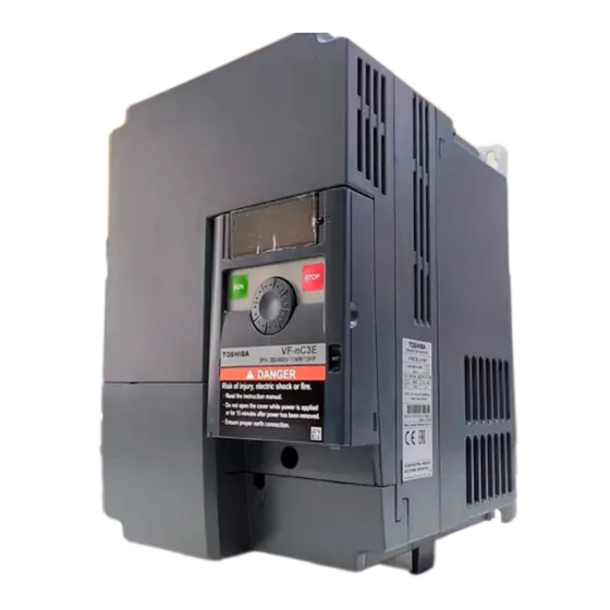
- Page 16 E6582233 Names and functions 1.3.1 Outside view With cover closed Charge lamp Indicates there is a high voltage still in the inverter. Do not open the terminal block cover when this lamp is lit because it is dangerous. Cover this is the body or terminal block cover.
- Page 17 E6582233 Example of the label [Opening the cover] l 14 About the monitor display The LED on the operation panel uses the following symbols to indicate parameters and operations. LED display (numbers) LED display (letters)
- Page 18 E6582233 Warning Never touch the internal terminals in the upper right while the front cover is open. There is a risk of shock because it carries a high voltage. Prohibited [With cover open] RUN lamp % lamp Lit when a frequency is Dispalyed numbers are not output with the ON percents.
- Page 19 E6582233 1.3.2 Opening the terminal cover Caution When removing and installing the terminal cover with a screwdriver, be sure not to scratch your hand as this results in injury. Pressing too hard on the screwdriver may scratch the inverter. Mandatory ...
- Page 20 E6582233 (2) Removing the power terminal cover (VFNC3E-4015P to 4055P) Insert a screwdriver or other thin object into the Press in on the screwdriver. hole indicated with the mark. While pressing on the screwdriver, rotate the Pull the terminal cover up at an angle. terminal cover downward to remove it.
- Page 21 E6582233 (3) Removing the power terminal cover (VFNC3E-4075P, 4110P) Insert a screwdriver or other thin object into the Press the screwdriver. hole indicated with the mark. While pressing on the screwdriver, pull the Pull up the wire trapping cover upward to terminal cover downward to remove it.
- Page 22 E6582233 1.3.3 Power circuit and control circuit terminal boards In case of the lug connector, cover the lug connector with insulated tube, or use the insulated lug connector. 1) Power circuit terminal board In case of the lug connector, cover the lug connector with insulated tube, or use the insulated lug connector.
- Page 23 E6582233 VFNC3E-4015P, 4022P M3.5 screw Earth Earth Earth terminal terminal terminal (M4 screw) (M5 screw) (M4 screw) ★ Bend the clips on the wiring port of the terminal cover to connect the PA/+, and PB terminals. VFNC3E-4037P , 4055P M4 screw Earth terminal (M5 screw)
- Page 24 E6582233 VFNC3E-4075P , 4110P M5 screw M5 screw Earth terminal (M5 screw) ★ Bend the clips on the wiring port of the terminal cover to connect the PA/+ and PB terminals. When using a crimping terminal, be sure to cover the fastener with an insulating tube or use an insulated crimping terminal.
- Page 25 E6582233 2) Control circuit terminal board The control circuit terminal board is common to all equipment. FLA FLB FLC CC VI P5 FM Connector for option (RJ45) OUT NO CC S2 P24 Recommended Stripping length: 6 (mm) Screw size tightening torque Screwdriver: Small-sized flat-blade screwdriver Optional connector 0.4 to 0.5 N ...
- Page 26 E6582233 Notes on the application 1.4.1 Motors When this inverter and the motor are used in conjunction, pay attention to the following items. Caution Use an inverter that conforms to the specifications of power supply and three-phase induction motor being operated. If the inverter being used does not conform to those specifications, not only will the three-phase induction motor not rotate correctly, but it may cause serious accidents through overheating Mandatory and fire.
- Page 27 E6582233 Low loads and low inertia loads The motor may demonstrate instability such as abnormal vibrations or overcurrent trips at light loads of 5% or under of the load percentage, or when the load's inertia moment is extremely small. If that happens reduce the carrier frequency.
- Page 28 E6582233 Motors with a brake When motors with a brake are directly connected to the inverter's output, the brake cannot be released at startup because of low voltage. Wire the brake circuit separately from the main circuit. 3-phase FLB FLC S2 (ST) NO CC 3-phase power...
- Page 29 E6582233 Power factor correction capacitor Power factor correction capacitors cannot be installed on the output side of the inverter. When a motor is run that has a power factor correction capacitor attached to it, remove the capacitors. This can cause inverter malfunction and capacitor destruction.
- Page 30 E6582233 Disposal Refer to chapter 15. 1.4.3 What to do about the leakage current Caution Current may leak through the inverter's input/output wires because of insufficient electrostatic capacity on the motor with bad effects on peripheral equipment. The leakage current’s value is affected by the carrier frequency and the length of the input/output wires. Mandatory Test and adopt the following remedies against leak current.
- Page 31 E6582233 Remedies: 1. Reduce PWM carrier frequency. The setting of PWM carrier frequency is done with the parameter Although the electromagnetic noise level is reduced, the motor acoustic noise is increased. 2. Use high frequency remedial products for earth leakage breakers (3) Influence of leakage current across lines Thermal relays Inverter...
- Page 32 E6582233 CT and ammeter If a CT and ammeter are connected externally to detect inverter output current, the leak current's high frequency component may destroy the ammeter. If the wires are ling (50 meters or more), or in case of models with motors of low rated current (several A (ampere) or less), the high frequency component of leakage current may pass through the externally connected CT and it may burn the ammeter connected CT, because the ratio of leakage current against the motor's rated current will increase.
- Page 33 If the inverter is installed in a location that is subject to vibration, anti-vibration measures are required. Please consult with Toshiba about these measures. If the inverter is installed near any of the equipment listed below, provide measures to insure against errors in operation.
- Page 34 Warning Do not install or operate the inverter if it is damaged or any component is missing. This can result in electric shock or fire. Contact your Toshiba distributor for repairs. Prohibited Mount the inverter on a metal plate.
- Page 35 E6582233 The space shown in the diagram is the minimum allowable space. Because air cooled equipment has cooling fans built in on the top or bottom surfaces, make the space on top and bottom as large as possible to allow for air passage.
- Page 36 E6582233 Panel designing taking into consideration the effects of noise The inverter generates high frequency noise. When designing the control panel setup, consideration must be given to that noise. Examples of measures are given below. Wire so that the main circuit wires and the control circuit wires are separated. Do not place them in the same conduit, do not run them parallel, and do not bundle them.
- Page 37 2. Connection Warning Never disassemble, modify or repair. This can result in electric shock, fire and injury. Call your Toshiba distributor for repairs. Disassembly prohibited Don't stick your fingers into openings such as cable wiring hole and cooling fan covers.
- Page 38 E6582233 Warning Ground must be connected securely. If the ground is not securely connected, it could lead to electric shock or fire when a malfunction or current leak occurs. Be Grounded Caution Do not attach devices with built-in capacitors (such as noise filters or surge absorber) to the output (motor side) terminal.
- Page 39 E6582233 Standard connections Warning Do not connect input power to the output (motor side) terminals (U/T1, V/T2, W/T3). Connecting input power to the output could destroy the inverter or cause a fire. First shut off input power and wait at least 15 minutes before touching wires on equipment (MCCB) that Prohibited is connected to inverter power side.
- Page 40 E6582233 2.2.1 Standard connection diagram 1 This diagram shows a standard wiring of the main circuit. Standard connection diagram - SINK (Negative) (common:CC) Braking resistor(Option) *1 PA/+ Motor MCCB U/T1 R/L1 Main circuit power supply S/L2 V/T2 Power 3ph-400V class: three-phase 380-460V T/L3 circuit W/T3...
- Page 41 E6582233 2.2.2 Standard connection diagram 2 Standard connection diagram - SOURCE (Positive) (common:P24) Braking resistor(Option) *1 PA/+ Motor MCCB Main circuit power supply U/T1 R/L1 S/L2 V/T2 3ph-400V class: three-phase 380-460V Power -50/60Hz circuit T/L3 W/T3 Control circuit VF-nC3C VF-nC3E Protective function Forward run command activation output...
- Page 42 E6582233 Description of terminals 2.3.1 Power circuit terminals This diagram shows an example of wiring of the main circuit. Use options if necessary. Power supply and motor connections VF-nC3E Connect the power Connect the motor Power supply cables to R/L1, S/L2, cables to U/T1, V/T2 and T/L3.
- Page 43 E6582233 Power circuit Terminal symbol Terminal function Grounding terminal for connecting inverter. There are 3 terminals in total. R/L1,S/L2,T/L3 400V class: three-phase 380 to 460V-50/60Hz U/T1,V/T2,W/T3 Connect to a (three-phase induction) motor. Connect to braking resistors. PA/+,PB Change parameters ,,, if necessary. The arrangements of power circuit terminals are different from each range.
- Page 44 E6582233 Terminal Input / Electrical Function Inverter internal circuits symbol output specifications Common Control circuit's equipotential terminal (2 to Input / terminals) output 5Vdc Output Analog power supply output (permissible load current: 10mA) Multifunction programmable analog input. Factory default setting: 0-10Vdc (1/1000 resolution) and 0-60Hz (0-50Hz) frequency input.
- Page 45 E6582233 Terminal Input / Electrical Function Inverter internal circuits symbol output specifications +24V Output 24Vdc power output 24Vdc-100mA Over current protection circuit This terminal can be used as an external OFF:f127=200 Input 24Vdc input for logic input terminal by changing parameter f127=200. Multifunction programmable open Open collector output collector output.
- Page 46 E6582233 Connection of SINK (Negative) logic/SOURCE (Positive) logic Current flowing out turns control input terminals on. These are called sink logic terminals. The general used method in Europe is source logic in which current flowing into the input terminal turns it Sink logic is sometimes referred to as negative logic, and source logic is referred to as positive logic.
- Page 47 E6582233 <Examples of connections when an external power supply is used> f127=200 f127=100 Sink (Negative) logic Source (Positive) logic Input Input Common Output Output (f127 = 100) (f127 = 200) Note 4) Common Output Output Common Input Input Common Programmable Programmable Inverter Inverter...
- Page 48 E6582233 Selecting the functions of the VI terminal between analog input and logic input The functions of the VI terminal can be selected between analog input and logic input by changing parameter settings (). (Factory default setting: Analog input 0-10V) Be sure to connect a resistor between P24 and VI terminals in case of sink logic, between VI and CC terminals in case of source logic.
- Page 49 If the inverter begins to emit smoke or an unusual odor, or unusual sounds, immediately turn power off. If the equipment is continued in operation in such a state, the result may be fire. Call your Toshiba distributor for repairs.
- Page 50 E6582233 Simplified Operation of the VF-nC3E The procedures for setting operation frequency and the methods of operation can be selected from the following. : (1) Run and stop using the panel keypad Run / Stop (2) Run and stop using external signals to terminal board : (1) Setting using setting dial Setting the frequency...
- Page 51 E6582233 3.1.1 How to run and stop [Example of a setting procedure] Panel operation LED display Operation Displays the operation frequency (operation stopped). (When standard monitor display selection = [Operation frequency]) MODE Displays the first basic parameter [History ()]. ...
- Page 52 E6582233 (3) Coast stop Coast stop The standard default is slowdown stop. To make a Motor coast stop, assign "6 (ST)" to an idle terminal. speed Change to = . For coast stop, open the ST-CC when stopping the motor in the state described at left.The monitor on the F-CC inverter at this time will display ...
- Page 53 E6582233 Example of operating from the panel (=: save even if power is off) Panel operation LED display Operation Display the operation frequency. (When standard monitor display selection is set as = [operation frequency]) Set the operation frequency. ...
- Page 54 E6582233 (2) Setting of frequency using external signals to terminal block (=) Frequency setting Setting the frequency using external potentiometer ★Potentiometer Setting frequency using the potentiometer (1-10k, 1/4W) Refer to section 6.6.2 for detailed adjustment. : Setting frequency 50 or 60Hz using potentiometer Frequency Note) Set parameter =.
- Page 55 E6582233 How to operate the VF-nC3E Overview of how to operate the inverter with simple examples. Setting the frequency using the setting dial, and run/stop using the Ex.1 panel keypad (1) Wiring PA/+ Motor U/T1 R/L1 V/T2 S/L2 W/T3 T/L3 Operation panel Parameter setting (default setting) Title...
- Page 56 E6582233 Setting the frequency using the setting dial, and run/stop using the Ex.2 panel keypad (2) Wiring PA/+ Motor U/T1 R/L1 V/T2 S/L2 W/T3 T/L3 Operation panel Parameter setting Title Function Programmed value Command mode selection Frequency setting mode selection ...
- Page 57 E6582233 Setting the frequency using the setting dial, and run/stop using Ex.3 external signals Wiring PA/+ Motor MCCB U/T1 R/L1 S/L2 V/T2 W/T3 T/L3 Forward Operation panel signal Reverse signal Common Parameter setting Title Function Programmed value Command mode selection ...
- Page 58 E6582233 Setting the frequency using external signals, run/stop using external Ex.4 signals. Wiring PA/+ Motor MCCB R/L1 U/T1 S/L2 V/T2 T/L3 W/T3 Forward signal Reverse signal Common Current signal: 420mA Voltage signal: 010V / 05V External potentiometer (Otherwise, input voltage signal between the terminals VI-CC.) Parameter setting Title Function...
- Page 59 E6582233 Meter setting and adjustment : Meter selection : Meter adjustment gain Function Output of 0 - 1mAdc, 0 (4) - 20mAdc, 0 - 10vdc can be selected for the output signal from the FM terminal, depending no the setting. Adjust the scale at . Use an ammeter with a full-scale 0 - 1mAdc meter.
- Page 60 E6582233 Resolution All FM terminals have a maximum of 1/255. Example of 4-20mA output adjustment (Refer to section 6.17.2 for details) =1, =0 =1, =20 (mA) (mA) Output Output currrent currrent f692 100% 100% Internal calculated value Internal calculated value Note 1) When using the FM terminal for current output, be sure that the external load resistance is less than 750Ω.
- Page 61 E6582233 [Example of how to adjustment the FM terminal frequency meter] Use the meter's adjustment screw to pre-adjust zero-point. Operation panel action LED display Operation Displays the output frequency. . (When standard monitor display selection is set to ) The first basic parameter “”...
- Page 62 E6582233 Setting the electronic thermal : Motor electronic-thermal protection level 1 : Electronic-thermal protection characteristic selection 3 : Motor electronic-thermal protection level 2 : Motor 150% overload detection time : Electronic-thermal memory Function This parameter allows selection of the appropriate electronic thermal protection characteristics according to the particular rating and characteristics of the motor.
- Page 63 E6582233 1) Setting the electronic thermal protection characteristics selection and motor electronic thermal protection level 1 , 2 The electronic thermal protection characteristics selection is used to enable or disable the motor overload trip function () and the overload stall function. While the inverter overload trip () will be in constant detect operation, the motor overload trip () can be selected using the parameter ...
- Page 64 E6582233 Output current reduction factor [%]/[A] ×1.0 ×0.6 30Hz Output frequency (Hz) Note: The motor overload protection start level is fixed at 30Hz. [Example of setting: When the VFNC3E-4007P is running with a 0.4kW motor having 1A rated current] Operation LED display Operation panel action...
- Page 65 E6582233 Setting of motor electronic thermal protection level 1 (Same as f173) If the capacity of the motor is smaller than the capacity of the inverter, or the rated current of the motor is smaller than the rated current of the inverter, adjust the electronic thermal protection level 1 so that it fits the motor's rated current.
- Page 66 E6582233 Note 1: At extremely low speeds of lower than 1 Hz or over 150%, an overload trip () occurs in a short period of time to protect the inverter. Note 2: If an inverter overload occurs with the factor default settings, the inverter is set to lower the carrier frequency automatically and overload tripping is () controlled.
- Page 67 E6582233 Preset-speed operation (speeds in 15 steps) - : Preset-speed frequency 1-7 - : Preset-speed frequency 8-15 Function A maximum of 15 speed steps can be selected just by switching an external logic signal. Multi-speed frequencies can be programmed anywhere from the lower limit frequency ...
- Page 68 E6582233 Preset-speed logic input signal example: (sink/source switching) =: With sink settings O: ON -: OFF (Speed commands other than preset-speed commands are valid when all are OFF) Preset-speed Terminal S1-CC S2-CC ...
- Page 69 E6582233 3) Using other speed commands with preset-speed command 1: Panel keypad (including extension panel), Command mode selection 0: Terminal board 2: RS485 communication 1: Setting dial 1 0: Terminal board 0: Terminal block (press in center to 1: Setting dial Frequency setting save) 3: RS485...
- Page 70 E6582233 4. Setting parameters Setting and Display Modes The VF-nC3E has the following three display modes. Standard monitor mode The standard inverter mode. This mode is enabled when inverter power goes on. This mode is for monitoring the output frequency and setting the frequency reference value. If also displays information about status alarms during running and trips.
- Page 71 E6582233 Status monitor mode The mode for monitoring all inverter status. Allows monitoring of set frequencies, output current/voltage and terminal information. Refer to chapter 8. The inverter can be moved through each of the modes by pressing the MODE key. ...
- Page 72 E6582233 How to set parameters There are two types of setting monitor modes: Easy mode and Standard setting mode. The mode active when power is turned on can be selected at (Registered parameter display selection), and the mode can be switched by the EASY key.
- Page 73 E6582233 Standard setting mode : The mode changes to the Standard setting mode when the EASY key is pressed and "" is displayed. Both basic and extended all parameters are displayed. Basic parameters : This parameter is a basic parameter for the operation of the inverter.
- Page 74 E6582233 4.2.1 Settings in the Easy setting mode The inverter enters this mode by pressing the MODE key when the Easy setting mode is selected Easy setting mode (Default registered parameters) When you are unsure of something Title Function during operation: ...
- Page 75 E6582233 4.2.2 Settings in the Standard setting mode The inverter enters this mode by pressing the MODE key when the Standard setting mode is selected. How to set basic parameters When you are unsure of something (1) Selects parameter to be changed. (Turn the setting dial.) during operation: You can return to the Standard monitor (2) Reads the programmed parameter setting.
- Page 76 E6582233 How to set extended parameters Each extended parameter is composed of an ""suffixed with a 3-digit figure, so first select and read out the heading of the parameter you want "" to "". ("": Parameter starting point is 100, "": Parameter starting point is 800.) (5) Select the title of the parameter you want to change.
- Page 77 E6582233 Reset parameters to default settings Use the parameter to reset all parameters back to their default settings. To use this function, set parameter =. Refer to section 4.3.2 for details. Call saved customer settings Customer settings can be batch-saved and batch-called. These settings can be used as customer-exclusive default settings.
- Page 78 E6582233 How to search and reprogram parameters Panel operation LED display Operation Displays the operation frequency (operation stopped). (When standard monitor display selection is set as = [operation frequency]) MODE Displays the first basic parameter "History function ()." Turn the setting dial, and select .
- Page 79 E6582233 4.3.2 Return to default settings : Default setting Function It is possible to return groups of parameters to their defaults, clear run times, and record/recall set parameters. [Parameter setting] Title Function Adjustment range Default setting 0: - 1: 50Hz default setting 2: 60Hz default setting 3: Default setting 1 (Initialization)
- Page 80 E6582233 Default setting 1 ( = ) Setting to will return parameters to the standard values that were programmed at the factory. ☆ When is set, is displayed for a short time after the settings are configured, and then disappears.
- Page 81 E6582233 EASY key function : Registered parameters display selection - : Easy setting mode parameter 1 to 24 • Function It is possible to switch between standard mode and easy setting mode using the EASY key. Up to 24 arbitrary parameters can be registered to easy setting mode. [Parameter setting] Title Function...
- Page 82 E6582233 [How to select parameters] In easy setting mode, only parameters registered to parameters 1 to 24 are displayed in order of registration. The values of the default settings are shown in the table below. [Parameter setting] Title Function Adjustment range Default setting -...
- Page 83 E6582233 5. Main parameters Before you operate the inverter, the parameters that you must first program are the basic parameters. Refer to section 11 tables of basic parameters. Searching for changes using the history function : History function History function (): Automatically searches for 5 latest parameters that are programmed with values different from the standard default setting and displays them in the .
- Page 84 E6582233 Parameter display MODE Press the MODE key to return to the parameter setting mode “.” MODE After that you can press the MODE key to return to the status monitor mode or the standard monitor mode (display of operation ...
- Page 85 E6582233 How to use the guidance function Here are the steps to follow to set parameters, using the guidance function. (When the basic setting guidance (auf) is set to 1) Operation panel LED display Operation action Displays the operation frequency (operation stopped). (When standard monitor display selection =...
- Page 86 E6582233 Table of parameters that can be changed using the guidance function Preset-speed setting Analog input operation Motor 2 switching operation Motor constant setting guidance guidance guidance guidance auf=2 auf=3 auf=4 auf=5 ...
- Page 87 E6582233 Setting acceleration/deceleration time :Automatic acceleration/deceleration :Acceleration time 1 :Deceleration time 1 Function 1) For acceleration time 1 programs the time that it takes for the inverter output frequency to go from 0Hz to maximum frequency . 2) For deceleration time 1 ...
- Page 88 E6582233 ☆ Setting acceleration/deceleration time (,) in conformance with mean load allows optimum setting that conforms to further changes in load. ☆ Use this parameter after actually connecting the motor. ☆ When the inverter is used with a load that fluctuates considerably, it may fail to adjust the acceleration or deceleration time in time, and therefore may be tripped.
- Page 89 E6582233 ☆ If the programmed value is shorter than the optimum acceleration/deceleration time determined by load conditions, overcurrent stall or overvoltage stall function may make the acceleration/deceleration time longer than the programmed time. If an even shorter acceleration/deceleration time is programmed, there may be an overcurrent trip or overvoltage trip for inverter protection.
- Page 90 E6582233 Note 1: The same characteristic can be obtained by setting the V/F control mode selection parameter to (automatic torque boost control) and the auto-tuning parameter to (auto-tuning). Refer to section 6.16 Note 2: Setting to automatically programs to . 2) When using vector control (increasing starting torque and high-precision operations) ...
- Page 91 E6582233 If vector control cannot be programmed First read the precautions about vector control in section 5.11-7). 1) If the desired torque cannot be obtained ⇒ Refer to section 6.16 selection 2 2) If auto-tuning error "" appears ⇒ Refer to section 6.16 selection 3 ...
- Page 92 E6582233 Selection of operation mode : Command mode selection : Frequency setting mode selection Function These parameters are used to specify which input device (operation panel, terminal board, or RS485 communication) takes priority in entering an operation stop command or frequency setting command (terminal block VI, setting dial 1 (storing by pressing center of setting dial), RS485 communication, or UP/DOWN from external logic).
- Page 93 E6582233 [Programmed value] A frequency command is set by means of external signals (VI terminal: 0 - 5/ : Terminal board VI 0 - 10 Vdc, or 0 (4) - 20 mAdc). Frequencies are set by rotating the setting dial on the inverter. Press the center : Setting dial 1 of the setting dial to save the frequency setting value.
- Page 94 E6582233 Example of run and frequency command switching Command mode and frequency setting mode switching Command mode selection With extension panel Terminal block RS485 communication (option) RKP007Z active (CMTB) priority clear Input terminal (SCLC) function Input terminal function :108/109 :48/49 Terminal block...
- Page 95 E6582233 Meter setting and adjustment : Meter selection : Meter adjustment gain Refer to section 3.3 for details. Forward/reverse run selection (Panel keypad) : Forward/reverse run selection (Panel keypad) Function Program the direction of rotation of the motor when the running and stopping are made using the RUN key and STOP key on the operation panel.
- Page 96 E6582233 ★ The inverter was factory-configured by default so that shorting terminals F-CC and terminals R-CC simultaneously would cause the motor to slow down to a stop. Using the parameter , however, you can select between forward run and reverse run. Maximum frequency : Maximum frequency ...
- Page 97 E6582233 Upper limit and lower limit frequencies : Upper limit frequency : Lower limit frequency Function Programs the lower limit frequency that determines the lower limit of the output frequency and the upper limit frequency that determines the upper limit of that frequency. Lower limit Upper limit Command frequency (Hz)
- Page 98 E6582233 5.10 Base frequency : Base frequency 1 : Base frequency voltage 1 Function Set the base frequency and the base frequency voltage in conformance with load specifications or the base frequency. Note: This is an important parameter that determines the constant torque control area. Base frequency voltage ...
- Page 99 E6582233 5.11 Selecting control mode : V/F control mode selection Function The V/F controls shown below can be selected. V/F constant Variable torque Automatic torque boost control *1 Vector control *1 Energy saving *1 ...
- Page 100 E6582233 [Setting V/F control mode selection to 3 (sensorless vector control)] Operation panel LED display Operation action Displays the operation frequency. (Perform during operation stopped.) . (When standard monitor display selection is set to [Operation frequency]) MODE ...
- Page 101 E6582233 2) Setting for fans and pumps Setting of V/F control mode selection to (variable torque) This is appropriate for load characteristics of such things as fans, pumps and blowers in which the torque in relation to load rotation speed is proportional to its square. Base frequency voltage ...
- Page 102 ★ Motor constant must be set If the motor you are using is a 4P Toshiba standard motor and if it has the same capacity as the inverter, there is basically no need to set the motor constant. In any other case, set the following parameters according to the motor's name plate.
- Page 103 ★ Motor constant must be set If the motor you are using is a 4P Toshiba standard motor and if it has the same capacity as the inverter, there is no need to set the motor constant. In any other case, set the following parameters according to the motor’s name plate.
- Page 104 E6582233 Base frequency V/f 5-point setting voltage 1 [V]/[%] Output frequency [Hz] Base frequency 1 Note 1: Restrict the value of torque to boost (vb) to 3% or so. Boosting the torque too much may impair the linearity between points.
- Page 105 E6582233 7) The maximum length of wires between the inverter and motor is 30 meters. If the wires are longer than 30 meters, set standard auto-tuning with the wires connected to improve low-speed torque during sensorless vector control. However the effects of voltage drop cause motor-generated torque in the vicinity of rated frequency to be somewhat lower.
- Page 106 E6582233 5.13 Setting the electronic thermal t : Motor electronic-thermal protection level 1 o : Electronic thermal protection characteristic selection Refer to section 3.4 for details 5.14 Preset-speed operation (speeds in 15 steps) s - : Preset-speed frequency 1-7 Refer to section 3.5 for details.
- Page 107 E6582233 6. Other parameters Extended parameters are provided for sophisticated operation, fine adjustment and other special purposes. Modify parameter settings as required. Refer to section 10 tables of extended parameters. Input/output parameters 6.1.1 Low-speed signal : Low-speed signal output frequency ...
- Page 108 E6582233 +24V +24V An example of the connection of the open collector An example of the connection of the relay OUT terminal (sink logic) output terminals Output terminal setting Default outputs low-speed signal (ON signal) to OUT terminal. This setting must be changed to invert the polarity of the signal.
- Page 109 E6582233 Output frequency [Hz] Designated frequency Setting frequency Designated frequency Time [s] Output frequency attainment signal : OUT-NO terminals Inversion of output frequency attainment signal 6.1.3 Output of set frequency speed reach signal : Speed reach setting frequency ...
- Page 110 E6582233 If the detection band value + the set frequency is less than the designated frequency Output frequency [Hz] + - Time [s] Set frequency attainment signal : OUT-NO terminals Inversion of set frequency attainment signal Input signal selection 6.2.1 Priority selection (Both F and R are ON)
- Page 111 E6582233 (1) [ = (Reverse)]: If an F command and an R command are entered simultaneously, the motor will run in the reverse direction. Output frequency [Hz] Setting frequency Forward run Time [s] Reverse run Setting frequency Forward run command Reverse run command (2) [ ...
- Page 112 E6582233 6.2.2 Changing the functions of VI terminal : Analog/logic input selection (VI terminal) Function This parameter allows you to choose between analog input and logic input for the VI terminal. [Parameter setting] Title Function Adjustment range Default setting 0: Voltage signal input (0 - 10V) Analog/logic input 1: Current signal input (4 - 20mA)
- Page 113 E6582233 Terminal function selection 6.3.1 Changing control logic switching : Sink/source switching Function Logic input terminal sink logic (minus common)/source logic (plus common) and using an external power supply are switched. [Parameter setting] Title Function Adjustment range Default setting 0: Sink(Internal power supply), 100: Source, ...
- Page 114 E6582233 Explanation of the coast stop function Coast stop When ST (Standby) is OFF, coast stops. Motor speed The default setting for ST (Standby) is ON, change the following settings. (no function) F-CC Assign open input terminal 6: ST (Standby). Coast stops if terminal set for ST (Standby) is set to ST-CC OFF.
- Page 115 E6582233 Basic parameters 2 6.4.1 Switching motor characteristics via terminal input : Base frequency 2 : Base frequency voltage 2 : Torque boost value 2 : Motor electronic-thermal protection level 2 : Stall prevention level 2 ...
- Page 116 E6582233 Setting of switching terminals To switch to motor 2, assign the following functions to a terminal not being used. It is also possible to switch to acceleration/deceleration 2 (AD2). Refer to section 6.17.1 for details. It is possible to set 3 functions for terminal F and R, and 2 functions for terminal S1 and S2. Input terminal function number Parameters changed from applicable parameters and default standards ...
- Page 117 E6582233 V/f 5-point setting f190 : V/f5-point setting VF1 frequency f196 : V/f 5-point setting VF4 frequency f191 : V/f 5-point setting VF1 voltage f197 : V/f 5-point setting VF4 voltage f192 : V/f 5-point setting VF2 frequency f198 : V/f 5-point setting VF5 frequency f193 : V/f 5-point setting VF2 voltage f199 : V/f 5-point setting VF5 voltage f194 : V/f 5-point setting VF3 frequency...
- Page 118 E6582233 6.6.2 Setting frequency command characteristics : Analog/logic input selection (VI terminal) : VI Input point 1 setting : VI Input point 1 frequency : VI Input point 2 setting : VI Input point 2 frequency ...
- Page 119 E6582233 1) 0-10Vdc voltage input adjustment VI termin al Po in t settin gs a dj ust the fre qu en cy co mma nd fo r the 50 ( H z) vo lta ge inp u t. ...
- Page 120 E6582233 6.6.3 Setting of frequency with the input from an external logic : External logic input - UP response time : External logic input - UP frequency steps : External logic input - DOWN response time : External logic input - DOWN frequency steps ...
- Page 121 E6582233 Adjustment with continuous signals (Operation example 1) Set parameters as follows to adjust the output frequency up or down in proportion to the frequency adjustment signal input time: Panel frequency incremental gradient = / setting time Panel frequency decremental gradient = ...
- Page 122 E6582233 <<Sample sequence diagram 2: Adjustment with pulse signals>> Forward / reverse command UP signal DOWN signal Set frequency clearing signal Upper limit frequency Command frequency(Hz) (The dotted lines represent effective output frequencies) If two signals are impressed simultaneously ...
- Page 123 E6582233 6.6.4 Fine adjustment of frequency setting signal : VI voltage bias : VI voltage gain Function These parameters are used to fine adjust the relation between the frequency setting signal input through the analog input terminal VI and the output frequency. Use these parameters to make fine adjustments after making rough adjustments using the parameters f201 to f204 .
- Page 124 E6582233 Operation frequency 6.7.1 Starting frequency : Starting frequency setting Function The frequency set with is put out as soon as operation is started. Use the parameter when a delay in response of starting torque according to the acceleration/deceleration time is probably affecting operation.
- Page 125 E6582233 DC braking : DC braking starting frequency : DC braking current : DC braking time Function A large braking torque can be obtained by applying a direct current to the motor. These parameters set the direct current to be applied to the motor, the application time and the starting frequency. [Parameter setting] Title Function...
- Page 126 E6582233 Time limit for lower-limit frequency operation : Time limit for lower-limit frequency operation : Hysteresis for lower-limit frequency operation Function If operation is carried out continuously at a frequency below the lower-limit frequency ( ) for the period of time set with ...
- Page 127 E6582233 6.10 Jump frequency - Avoiding frequency resonance : Jump frequency : Jumping width Function Resonance due to the natural frequency of the mechanical system can be avoided by jumping the resonant frequency during operation. During jumping, hysteresis characteristics with respect to the jump frequency are given to the motor.
- Page 128 E6582233 6.12 PWM carrier frequency : PWM carrier frequency : Random mode : Carrier frequency control mode selection Function 1) The parameter allows the tone of the magnetic noise from the motor to be changed by switching the PWM carrier frequency.
- Page 129 E6582233 Reduction of rated current. 55 ℃ or less *1 50 ℃ or less 55 ℃ *2 Ambient temperature Carrier frequency 2-4kHz 4.1-12kHz 4.1-12kHz VFNC3E-4004P 1.5A 1.2A 1.1A VFNC3E-4007P 2.3A 1.5A 1.2A VFNC3E-4015P 4.1A 4.0A 3.6A VFNC3E-4022P 5.5A 4.2A 4.0A VFNC3E-4037P 9.5A 8.8A...
- Page 130 E6582233 6.13 Trip-less intensification 6.13.1 Auto-restart (Restart of coasting motor) : Auto-restart control selection Caution Stand clear of motors and mechanical equipment If the motor stops due to a momentary power failure, the equipment will start suddenly when power is restored.
- Page 131 E6582233 2) Restarting motor during coasting (Motor speed search function) Motor speed Forward / reverse ST-CC ★ Setting = or : This function operates after the ST-CC terminal connection has been opened first and then connected again. Note 1: The terminal function ST needs to be assigned to an input terminal, using the parameters to .
- Page 132 E6582233 6.13.2 Regenerative power ride-through control (Deceleration stop) : Regenerative power ride-through control (Deceleration stop) Function 1) Regenerative power ride-through control: When momentary power failure occurs during operation, this function makes operation continue using the regeneration energy from a motor. 2) Deceleration stop during power failure: When momentary power failure occurs during operation, this function stops the motor quickly and compulsorily using the regeneration energy from the motor.
- Page 133 E6582233 [If momentary power failure occurs] Input voltage DC Voltage Motor speed Normal acceleration Note 3: If momentary power failure occurs during deceleration stop, power ride-through control will not be performed. An example of setting when f302=2 Input voltage Motor speed Time Deceleration stop...
- Page 134 E6582233 6.13.3 Retry function : Retry selection (number of times) Caution Do not go near the motor in alarm-stop status when the retry function is selected. The motor may suddenly restart, which could result in injury. Take measures for safety, e.g. attach a cover to the motor, to prevent accidents if the motor suddenly Mandatory restarts.
- Page 135 E6582233 6.13.4 Dynamic (regenerative) braking - For abrupt motor stop f304 : Dynamic braking selection f308 : Dynamic braking resistance f309 : Dynamic braking resistor capacity f626 : Over-voltage stall protection level Function VFNC3E-4004P,4007P models don’t have the PA/+ and PB terminals and cannot be used with the braking resistor.
- Page 136 E6582233 1) Connecting an external braking resistor (optional) Separate-optional resistor (with thermal fuse) Braking resistor (optional) MCCB PA/+ Motor U/T1 R/L1 Three-phase main circuits V/T2 S/L2 Power supply W/T3 T/L3 Inverter Connecting thermal relays and an external braking resistor TH -R Braking resistor (optional) MCCB PA/+...
- Page 137 E6582233 [Parameter setting] Title Function Setting Dynamic braking selection f304 Overvoltage limit operation f305 Dynamic braking resistance Proper value f308 f309 Dynamic braking resistor capacity Proper value f626 Over-voltage stall protection level 136 (%) ★ To use this inverter in applications that create a continuously regenerative status (such as downward movement of a lift, a press or a tension control machine), or in applications that require deceleration stopping of a machine with a significant load inertial moment, increase the dynamic braking resistor capacity according to the operation rate required.
- Page 138 Note 3: Type-form of “PBR-” indicates the thermal fuse”. Type-form of “PBR7-“ indicates the thermal fuse and thermal relay. Note 4: VFNC3E-4055P and VFNC3E-4110P: Default setting of parameter f308 and f309 is for previous Toshiba breaking resistor PBR3-. Set parameter f308 and f309 to following table value. f308...
- Page 139 E6582233 6.13.5 Avoiding overvoltage tripping : Overvoltage limit operation f626 : Over-voltage stall protection level Function These parameters are used to keep the output frequency constant or increase it to prevent overvoltage tripping in case the voltage in the DC section rises during deceleration or varying speed operation.
- Page 140 E6582233 6.13.6 Output voltage adjustment/Supply voltage correction : Base frequency voltage 1 : Supply voltage correction (output voltage limitation) Function Base frequency voltage1 The parameter adjusts the voltage corresponding to the base frequency 1 so that no voltage exceeding the ...
- Page 141 E6582233 [ : No voltage compensation/output voltage limited] [ : Voltage compensation/output voltage limited] Input voltage High Input voltage Input voltage High Output frequency Output frequency * The above applies when V/F control mode selection parameter ...
- Page 142 E6582233 6. 14 Braking function 6.14.1 Brake sequence control f340 : Creeping time 1 f345 : Brake release time f341 : Braking mode selection f346 : Creeping frequency f343 : Torque bias input f347 : Creeping time 2 • Function These parameters can be used as brake sequences for lifts and similar equipment.
- Page 143 E6582233 Creepinjg frequency Output frequency Torque control Speed control [Hz] Starting frequency Time [s] Torque Issue of torque command Braking request Braking signal Brake release request Braking operation RUN command Note 1) Do not change the RUN/STOP and the forward/reverse signal during creep operation. Set the interlock circuit not to change the above switching.
- Page 144 E6582233 [Parameter setting] Title Function Adjustment range Default setting PID control waiting time 0-2400 [s] PID control 0: Disabled, 1: Enabled Proportional gain 0.01-100.0 0.30 Integral gain 0.01-100.0 0.20 Differential gain 0.00-2.55 0.00 PID forward/reverse characteristics 0: Forward ...
- Page 145 E6582233 3) Setting PID control Set "" in the extended parameter (PID control) Set parameters (acceleration time), and (deceleration time) to the system fitting values. To limit the output frequency, set parameters (upper limit frequency) and (lower limit frequency).
- Page 146 E6582233 Assign an input terminal function 52 (PID integral/derivative) to an input terminal, when that input ★ terminal is ON, it is possible to calculate integral/derivative amounts always as 0 (zero). (D-gain adjustment parameter) This parameter adjusts the differential gain level during PID control. This gain increases the speed of response to a rapid change in deviation (difference between the process value and the feedback value).
- Page 147 E6582233 6) Setting the time elapsed before PID control starts You can specify a waiting time for PID control to prevent the inverter from starting PID control before the control system becomes stable, for example, after start-up. The inverter ignores feedback input signals, carries out operation at the frequency determined by the amount of processing for the period of time specified with ...
- Page 148 E6582233 6.16 Setting motor constants : Auto-tuning : Motor rated current : Slip frequency gain : Motor no-load current : Automatic torque boost value : Motor rated speed : Motor rated capacity : Load inertia moment ratio To use vector control, automatic torque boost and automatic energy saving, motor constant setting (motor tuning) is required.
- Page 149 E6582233 [Selection 2: Setting vector control and auto-tuning independently] Set vector control, automatic torque boost, and energy saving and auto-tuning individually. After setting (V/F control mode selection), auto-tuning occurs. Set the auto-tuning parameter to (Auto-tuning enabled) [Parameter setting] Title Function Adjustment range...
- Page 150 E6582233 Setting procedure Adjust the following parameters: : Set the compensation gain for the slipping of the motor. A higher slip frequency reduces motor slipping correspondingly. After setting , set to adjust in detail. Be careful as inputting a value larger than necessary causes hunting and other unstable operation. : Adjust the primary resistive component of the motor.
- Page 151 E6582233 6.17 2nd acceleration/deceleration 6.17.1 Switching acceleration/deceleration time 1 & 2 :Acceleration time 2 :Deceleration time 2 : Acceleration/deceleration 1 & 2 switching frequency Function Acceleration and deceleration times can be set individually. Select from the following two methods for selecting and switching.
- Page 152 E6582233 2) Switching according to terminal (switching acceleration/deceleration time by external terminal) Output frequency [Hz] Time [s] Second acceleration/deceleration selection signal (3) Acceleration at ramp of (1) Acceleration at ramp of deceleration time acceleration time (2) Acceleration at ramp of (4) Acceleration at ramp of acceleration time ...
- Page 153 E6582233 1) Linear acceleration/deceleration Normal acceleration/deceleration Output frequency [Hz] pattern. Max. frequency Normally, this setting can be used. Time [s] 2) S-pattern acceleration/deceleration 1 Used when necessary to accelerate or decelerate in a short period of time up to a high-speed area over 60 Hz, and to moderate shock at acceleration.
- Page 154 E6582233 6.18 Protection functions 6.18.1 Setting motor electronic thermal protection : Motor electronic-thermal protection level 1 173 : Motor electronic-thermal protection level 2 : Motor 150% overload detection time : Electronic-thermal memory Function This parameter allows selection of the appropriate electronic thermal protection characteristics according to the particular rating and characteristics of the motor.
- Page 155 E6582233 [Parameter setting] Title Function Adjustment range Default setting Stall prevention level 1 10-199 (%) / (A), 200: Disabled Stall prevention level 2 [Display during operation of the stall prevention] During an alarm status, (that is , when there is a current flow in excess of the stall prevention level), the output frequency changes.
- Page 156 E6582233 ■ Flow of operation when = Reset the Completion of reset Normal operation inverter by panel or terminal Occurrence of a operation. The relay trips again. trip If the cause of the ・Display of the cause trip is not ・Failure signal FL Turn power off, eliminated...
- Page 157 E6582233 2) Emergency stopping from the operation panel Emergency stopping from the operation panel is possible by pressing the STOP key on the panel twice while the inverter is not in the panel control mode. (1) Press the STOP key ......" " will blink. (2) Press the STOP key once again ...
- Page 158 E6582233 6.18.6 Input phase failure detection : Input phase failure detection selection Function This parameter detects inverter input Phase failure. If the abnormal voltage status of main circuit capacitor persists for few minutes or more, the tripping function and the FL relay will be activated. Trip display is ...
- Page 159 E6582233 [Parameter setting] Function Adjustment range Default setting Title Small current detection hysteresis 1-20 (%) 0: Alarm only Small current trip/alarm selection 1: Tripping Small current detection current 0-150 (%) / (A) Small current detection time 0-255 (s) <Example of operation>...
- Page 160 E6582233 [Parameter setting] Function Adjustment range Default setting Title 0: Each time (standard pulse) 1: Only one time after power on Detection of output short-circuit at (standard pulse) start-up 2: Each time (short pulse) 3: Only one time after power on (short pulse) 6.18.9 Over-torque trip ...
- Page 161 E6582233 <Example of operation> 1) Output terminal function: 28 (OT) Over-torque detection = (Alarm only) Over-torque signal output less than - Torque (%) Time [sec] When = (tripping), the inverter will trip if over-torque lasts for the period of time set with .
- Page 162 E6582233 6.18.11 Cumulative operation time alarm setting : Cumulative operation time alarm setting Function This parameter allows you to set the inverter so that it will put out an alarm signal after a lapse of the cumulative operation time set with . "0.1"...
- Page 163 E6582233 6.18.13 VI analog input break detection : VI analog input break detection level Function The inverter will trip if the VI value remains below the specified value for about 0.3 seconds. In such a case, "" is displayed. =0: Disabled..Not detected.
- Page 164 E6582233 6.18.15 Number of starting alarm f648 : Number of starting alarm Function Counting the number of starting, when it will reach the value of parameter f648 setting, it will be displayed and alarm signal is output. [Parameter setting] Title Function Adjustment range...
- Page 165 E6582233 6.19 Adjustment parameters 6.19.1 Pulse train output for meters : Logic output/pulse train output selection (OUT) : Pulse train output function selection (OUT) : Maximum numbers of pulse train Function Pulse trains can be sent out through the OUT output terminals. To do so, it is necessary to select a pulse output mode and specify the number of pulses.
- Page 166 E6582233 6.19.2 Calibration of analog output : Analog output signal selection : Inclination characteristic of analog output : Analog output bias Function Output signal from the FM terminal can be switched between 0 to 1mAdc output, 0 to 20mAdc output, and 0 to 10Vdc output with the ...
- Page 167 E6582233 6.20 Operation panel parameter 6.20.1 Prohibition of key operations and parameter settings f700 : Parameter protection selection f730 : Panel frequency setting prohibition (fc) f731 : Disconnection detection of extension panel f732 : Local/remote key prohibition of extension panel f733 : Panel operation prohibition (RUN key) f734 : Panel emergency stop operation prohibition f735 : Panel reset operation prohibition...
- Page 168 E6582233 Title Function Adjustment range Default setting 0: Password unset f738 Password setting ( f700 ) 1-9998 9999: Password set 0: Password unset f739 Password verification 1-9998 9999: Password set ★ Assigning the parameter editing permission (function number 110, 111) to any logic input terminal, parameters can be written regardless of the setting of f700 .
- Page 169 E6582233 ■Prohibit changing parameter settings with logic input Set "Parameter editing prohibited" for any input terminal. Activating the "Parameter editing prohibited" function prevents changes to all parameters. The following table shows an example of setting input terminal S2. Title Function Adjustment range Setting Input terminal selection 4A...
- Page 170 E6582233 6.20.2 Changing the unit (A/V) from a percentage of current and voltage :Current/voltage unit selection Function These parameters are used to change the unit of monitor display. % A (ampere)/V (volt) Current 100% = Rated current of inverter Input voltage 100% = 400Vac Output voltage 100% = 400Vac ...
- Page 171 E6582233 6.20.3 Displaying the motor or the line speed : Free unit display scale Function The frequency or any other item displayed on the monitor can be converted freely into the rotational speed of the motor, the operating speed of the load, and so on. The value obtained by multiplying the displayed frequency by the -set value will be displayed as follows: Value displayed = Monitor-displayed or parameter-set frequency ...
- Page 172 E6582233 [Parameter setting] Title Function Adjustment range Default setting 0.00: Disabled (display of frequency) Free unit display scale 0.00 0.01-200.0 The converts the following parameter settings: Free unit Frequency monitor display Operation frequency command, Operation frequency, PID feedback, Frequency command value After correction, Operation frequency command at trip , , , , ...
- Page 173 E6582233 6.20.5 Changing the initial display of the panel : Initial panel display selection : Initial extension panel display selection Function This parameter specifies display format while power is ON. Changing the display format while power is ON When the power is ON, the standard monitor mode displays the operation frequency (default setting) in the format of ""...
- Page 174 E6582233 6.20.8 Parameter registration to easy setting mode - : Easy setting mode parameter 1 to 24 Up to 24 arbitrary parameters can be registered to easy setting mode. Refer to section 4.4 for details. 6.21 Communication function (RS485) ...
- Page 175 E6582233 ★ 2-wire RS485 communication option is as follows. (1) USB communication exchange unit (Type: USB001Z) Cable for communication between the inverter and the unit (Type: CAB0011 (1m), CAB0013 (3m), CAB0015 (5m)) Cable for communication between the unit and computer: Use a commercially available USB 1.1 or 2.0 cables.
- Page 176 Communication time-out detection 1: Communication selection of condition fmod or cmod 2: 1 during operation Selection of communication 0: Toshiba inverter protocol protocol 1: ModbusRTU protocol 0: No selection 1: Command information Block write data 1 ...
- Page 177 E6582233 Communication function settings Commands and frequency settings are given priority by communication. (Prioritized by commands from the panel or terminal block.) Thus, command and frequency settings from communication are activated, regardless of the command mode selection () or frequency settings mode selection settings (). However, setting 48: SCLC (switching from communication to local) with input terminal function selection and when inputting from an external device, it is possible to operate at command mode selection () and frequency setting mode selection () settings.
- Page 178 E6582233 Configuration of RS485 connector and wiring Inverter viewed RS485 Name Description from bottom number communication For factory Do not connect (SG) Ground Same phase RXD+/TXD+ reception data Using Anti-phase RXD-/TXD- reception data Pin-1 Pin-8 Open Power supply Do not connect for option Ground Using...
- Page 179 E6582233 Connection example when using the computer link function <Independent communication> Perform computer-inverter connection as follows to send operation frequency commands from the host computer to inverter No. 3: ~ ~ : Wiring H ost c omputer : Data (Host → INV) : Response data (INV →...
- Page 180 E6582233 <Broadcast communication> When sending an operation frequency command via a broadcast from the host computer ~ ~ : Wiring H ost c omputer : Data (Host → INV) : Response data (INV → Host) INV N o.00 INV No.01 INV No.02 INV No.03 INV No.29...
- Page 181 E6582233 7. Operations with external signal Operating external signals You can control the inverter externally. The parameter settings differ depending upon your method of operation. Determine your method of operation (the operational signal input method, speed command input method) before using the procedure below to set the parameters.
- Page 182 E6582233 Applied operations by an I/O signal (operation from the terminal block) 7.2.1 Input terminal function This function is used to send a signal to the input terminal from an external programmable controller to operate or configure the inverter. The ability to select from a variety of functions allows for flexible system design. [Control terminal board] FLA FLB FLC CC VI P5 FM...
- Page 183 E6582233 Connecting For logic input a Inverter With sink settings Relay a-contact Input terminal Operates by short circuiting between the input terminal and CC (common). Use for forward rotation, reverse rotation, and multi-stage speed. For connection (sink logic) via transistor output Inverter Programmable controller Input terminal...
- Page 184 E6582233 Usage example 1 ··· 3-wire operation (one-push operation) Use the 3-wire operation function to operate the inverter, maintaining operation without using the sequence circuit by inputting an external signal (reset logic signal). Forward run Forward run (F) : Pressing forward run (F) rotates forward at the specified frequency command value.
- Page 185 E6582233 Note 5) Be aware that DC braking continues even if a startup signal is input during DC braking. Note 6) Only F and R maintain HD (operation hold). When using F or R in combination with other functions, be aware that the other functions do not hold. For example, when F and SS1 are assigned, F holds, but SS1 does not.
- Page 186 E6582233 List of logic input terminal function settings Parameter Parameter programmed value programmed value Function Function Positive Negative Positive Negative logic logic logic logic No function PID control prohibition ...
- Page 187 E6582233 7.2.2 Output terminal function (sink logic) This function is used to output a variety of signals to external devices from the inverter. With the logic output terminal function, you can select from multiple output terminal functions. Set two types of functions for the OUT terminal and then you can output when either one or both of them is ON.
- Page 188 E6582233 Assign two types of functions to the output terminal (OUT) Terminal Title Function Adjustment range Default setting symbol Output terminal 4 (Low-speed detection selection 1A signal) 0 - 255 Output terminal 255 (Always ON) selection 1B Output terminal logic 0: ...
- Page 189 E6582233 List of output terminal function settings <Explanation of terminology> Alarm …... Alarm output when a setting has been exceeded. Pre-alarm …... Alarm output when the inverter may cause a trip during continued operation. List of detection levels for output terminal selection Parameter programmed Parameter value...
- Page 190 E6582233 Speed instruction (analog signal) settings from external devices You can select from voltage input (0 to 10V, 0 to 5V), and current input (4 to 20mA) for an analog input terminal (VI). The maximum resolution is 1/1000. [Control terminal block] FLA FLB FLC CC VI P5 FM OUT NO CC F...
- Page 191 E6582233 7.3.1 Settings depending on voltage (0 to 10 V) input You can set the frequency settings by inputting an analog voltage signal of 0 to 10Vdc between the VI and CC terminals. The following shows examples when the run command is input from the terminal. Title Function Adjustment range...
- Page 192 E6582233 7.3.2 Settings depending on current (4 to 20 mA) input You can set the frequency settings by inputting an analog current signal of 4 (0) to 20mA dc between the VI and CC terminals. The following shows examples when the run command is input from the terminal. Title Function Adjustment range...
- Page 193 E6582233 7.3.3 Settings depending on voltage (0 to 5 V) input <external potentiometer> You can set the frequency by connecting the FRH kit (optional), or a potentiometer (1 to 10kΩ – 1/4W) to the VI terminal. Connect the potentiometer between the P5, VI, and CC terminals. The standard voltage for the P5 terminal is 5Vdc. Instead of using the potentiometer, you can set the frequency settings by inputting an analog voltage signal of 0 to 5Vdc between the VI and CC terminals.
- Page 194 E6582233 8. Monitoring the inverter status in operation / before tripping Flow of status monitor mode Status monitor mode Flow of monitor as following About Setting monitor mode 20 kinds of data MODE MODE ☆ Display mode ( Refer to section 4.1) Standard monitor mode 60.0 ...
- Page 195 E6582233 Status monitor mode 8.2.1 Status monitor under normal conditions In this mode, you can monitor the operation status of the inverter. To display the operation status during normal operation: Press the MODE key twice. Setting procedure (eg. operation at 40Hz) Panel Communic Item displayed...
- Page 196 E6582233 (Continued) Panel Communic Item displayed Description ation No. operated display The ON/OFF status of each of the control signal input terminals (F, R, S1, S2, VI) is displayed in bits. }}i}i ON : a }}i}i OFF: FE06 Note 4 Input terminal The ON/OFF status of each of the control signal...
- Page 197 E6582233 (Continued) Panel Communic Item displayed Description ation No. operated display Parts replacement The ON/OFF status of each of the cooling fan, alarm information circuit board capacitor, main circuit capacitor of parts replacement alarm or cumulative operation time are displayed in bits. ON : ...
- Page 198 E6582233 (Continued) Panel Item displayed LED display Description operated The inverter output voltage when the trip occurred is Output voltage displayed. (%/V) The ON/OFF statuses of the control input terminals ( F, R, S1, S2, V I ) are displayed in bits. ON : ...
- Page 199 E6582233 Display of trip information 8.3.1 Trip code display If the inverter trips, an error code is displayed to suggest the cause. Since trip records are retained, information on each trip can be displayed anytime in the status monitor mode. Refer to section 12.1 for details about trip code display.
- Page 200 E6582233 (Continued) Panel Communic Item displayed Description ation No. operated display The ON/OFF statuses of the control input terminals (F, R, S1, S2, VI) are displayed in bits. }}i}i ON : Note 4 a }}i}i OFF: Input terminal FE06 The ON/OFF status of each of the control signal output terminals (OUT and FL) at the occurrence...
- Page 201 E6582233 (Continued) Panel Communic Item displayed Description ation No. operated display The ON/OFF status of each of the cooling fan, circuit board capacitor, main circuit capacitor of parts replacement alarm or cumulative operation time are displayed in bits. ON : Note 7 }}}} OFF: ...
- Page 202 E6582233 Output voltage: The voltage displayed is the output command voltage. 100% reference value is 400V on 400V models. This unit can be switched to V (volts). Torque current: The reference value (100% value) is the rated output current indicated on the nameplate.
- Page 203 E6582233 9. Peripheral devices Warning When using switchgear for the inverter, it must be installed in a cabinet. Failure to do so can lead to risk of electric shock and can result in death or serious injury. Mandatory action ...
- Page 204 E6582233 Selection of wiring devices Molded case circuit breaker (MCCB) Magnetic contactor Input current (A) Applicable Earth leakage circuit breaker (ELCB) (MC) (Note 1 to 3) Voltage motor Rated current (A) Rated current (A) class Without (kW) With ACL Without ACL With ACL Without ACL...
- Page 205 E6582233 Installation of a magnetic contactor If using the inverter without installing a magnetic contactor (MC) in the primary circuit, use an MCCB (with a power cut off device) to open the primary circuit when the inverter protective circuit is activated. When using an optional brake module, install a magnetic contactor (MC) or molded-case circuit breaker with a power cutoff device on the primary power supply of the inverter, so that the power circuit opens when the failure detection relay (FL) in the inverter or the externally installed overload relay is actuated.
- Page 206 ( ) and appropriate to the motor used should be installed between the inverter and the motor. When using a motor with a current rating different to that of the corresponding Toshiba general-purpose motor When operating a single motor with an output smaller than that of the applicable standard motor or more than one motor simultaneously.
- Page 207 E6582233 Optional external devices The following external devices are optionally available for this inverter series. Power supply Molded-case circuit breaker MCCB Magnetic contactor (1) Input AC reactor (ACL) Extension panel : RKP007Z Remote control panel : CBVR-7B1 Frequency meter : QS6T Zero-phase reactor FRH kit : FRH kit...
- Page 208 E6582233 10. Table of parameters and data 10.1 Frequency setting parameter Minimum setting unit Default User Title Function Unit Adjustment range Reference Panel/Communication setting setting Operation 0.1/0.01 - 3.1.2 frequency of operation panel 10.2 Basic parameters Four navigation functions Minimum Communicati setting unit...
- Page 209 E6582233 Minimum Communicati setting unit Default User Ti tle Function Unit Adjustment range Reference on No. Panel/Comm setting setting unication FMSL 0005 Meter selection 0: Output frequency 1: Output current 2: Frequency reference 3: Input voltage (DC detection) 4: Output voltage (command value) 5 to 11: - 12: Frequency setting value (after compensation)
- Page 210 E6582233 Minimum Communicati setting unit Default User Title Function Unit Adjustment range Reference on No. Panel/Comm setting setting unication Setting Overload protection OL stall 0017 Electronic-thermal valid invalid protection valid valid Standard characteristic motor invalid invalid selection invalid valid valid invalid valid...
- Page 211 E6582233 10.3 Extended parameters Input/output parameters 1 Minimum Communicati setting unit Default User Ti tle Function Unit Adjustment range Reference on No. Panel/Comm setting setting unication F100 0100 Low-speed signal 0.1/0.01 0.0- 6.1.1 output frequency F101 0101 Speed reach 0.1/0.01 0.0-...
- Page 212 E6582233 Minimum Communicati setting unit Default User Title Function Unit Adjustment range Reference on No. Panel/Comm setting setting unication F151 0151 Input terminal 0-201 6.3.3 selection 1B (F) 6.6.1 F152 0152 Input terminal 0-201 7.2.1 selection 2B (R) ...
- Page 213 E6582233 Frequency parameters Minimum Communicati setting unit Default User Ti tle Function Unit Adjustment range Reference Panel/Comm setting setting on No. unication F201 0201 VI input point 1 0-100 6.6.2 setting F202 0202 VI input point 1 0.1/0.01 0.0-400.0 ...
- Page 214 E6582233 Minimum Communicati setting unit Default User Title Function Unit Adjustment range Reference Panel/Comm setting setting on No. unication F292 0292 Preset-speed 0.1/0.01 frequency 13 6.11 F293 0293 Preset-speed 0.1/0.01 frequency 14 F294 0294 0.1/0.01 ...
- Page 215 E6582233 Minimum Communicati setting unit Default User Ti tle Function Unit Adjustment range Reference on No. Panel/Comm setting setting unication F311 0311 Reverse-run 0: Forward/reverse run permitted 6.13.7 prohibition 1: Reverse run prohibited 2: Forward run prohibited F312 0312 Random mode 0: Disabled...
- Page 216 E6582233 Torque boost parameters 1 Minimum Communicati setting unit Default User Title Function Unit Adjustment range Reference on No. Panel/Comm setting setting unication F400 0400 Auto-tuning 6.16 0: Auto-tuning disabled 1: Initialization of (reset to 0) 2: Auto-tuning executed (after execution: 0) F401 0401...
- Page 217 E6582233 Torque boost parameters 2 Minimum Communicati setting unit Default User Ti tle Function Unit Adjustment range Reference ons No. Panel/Comm setting setting unications F480 0480 Motor specific coefficient 7 F485 0485 Motor specific coefficient 8 F491 0491 Motor specific coefficient 8A...
- Page 218 E6582233 Minimum Communicati setting unit Default User Title Function Unit Adjustment range Reference on No. Panel/Comm setting setting unication F609 0609 Small current 1-20 6.18.7 detection hysteresis F610 0610 Small current 0: Alarm only trip/alarm 1: Tripping selection F611 0611 Small current...
- Page 219 E6582233 Output parameters Minimum Communicati setting unit Default User Ti tle Function Unit Adjustment range Reference on No. Panel/Comm setting setting unication F669 0669 Logic output/pulse 0: Logic output 6.19.1 train output 1: Pulse train output selection (OUT) F676 0676 Pulse train output...
- Page 220 E6582233 Minimum Communicati setting unit Default User Title Function Unit Adjustment range Reference Panel/Comm on No. setting setting unication F710 0710 Initial panel 0: Operation frequency (Hz/free unit) 6.20.5 display selection 1: Output current (%/A) 8.3.2 2: Frequency setting value (Hz/free unit) 3 to 17: - 18: Arbitrary code from communication 19 to 33: -...
- Page 221 E6582233 Minimum Communicati setting unit Default User Ti tle Function Unit Adjustment range Reference Panel/Comm on No. setting setting unication F746 0746 Factory specific coefficient 7A F749 0749 Integrating 0: 1 = 100 kWh 6.20.7 wattmeter display 1: 1 = 1,000 kWh unit selection 2: 1 = 10,000 kWh 3: 1 = 100,000 kWh...
- Page 222 0: Valid at any time time-out detection 1: Communication selection of condition fmod or cmod 2: 1 + during operation F829 0829 Selection of 0: Toshiba inverter protocol communication 1: Modbus RTU protocol protocol F870 0870 Block write data 1 0: No selection ...
- Page 223 E6582233 10.4 Default settings by inverter rating Dynamic Integrating Dynamic Automatic Motor Torque braking Motor rated Motor rated wattmeter braking torque no-load boost value resistor capacity current display unit resistance boost value current capacity selection Inverter type / ...
- Page 224 E6582233 10.5 Input Terminal Function Table of input terminal functions 1 Function Code Function Action Reference No function Disabled Forward run command ON: Forward run, OFF: Slowdown stop 3.1.1 Inversion of forward run command Inversion of F 7.2.1 Reverse run command ON: Reverse run, OFF: Slowdown stop 3.1.1 Inversion of reverse run command...
- Page 225 E6582233 Table of input terminal functions 2 Function Code Function Action Reference Frequency UP ON: Frequency increased 6.6.3 OFF: Frequency increase canceled Inversion of frequency UP Inversion of UP Frequency DOWN ON: Frequency decreased OFF: Frequency decrease canceled DWNN Inversion of frequency DOWN Inversion of DWN Clear frequency UP/DOWN...
- Page 226 E6582233 Input terminal function priority 6,7 8,9 10,11 24,25 36,37 88,89 12,13 28,29 52,53 90,91 Function 14,15 32,33 54,55 92,93 Code 16,17 ○ ○ ○ ○ ○ ○ ○ ○ ○ ◎ ○ ◎ ◎ ○ ◎ ○ ○ ○...
- Page 227 E6582233 10.6 Output Terminal Function Table of output terminal functions 1 Function Code Function Action Reference Frequency lower limit ON: Output frequency is more than OFF: Output frequency is or less Inversion of frequency lower limit Inversion of LL Frequency upper limit ON: Output frequency is or more OFF: Output frequency is less than ...
- Page 228 E6582233 Table of output terminal functions 2 Function Code Function Action Reference Run/stop ON: While operation frequency is output or DC braking is in 3.1.1 operation () OFF: Operation stopped RUNN Inversion of run/stop Inversion of RUN Cumulative operation time alarm ON: Cumulative operation time is ...
- Page 229 E6582233 11. Specifications 11.1 Models and their standard specifications Standard specifications Item Specification Input voltage class 3-phase 400V class Applicable motor (kW) 0.75 Type VFNC3E Form 4004P 4007P 4015P 4022P 4037P 4055P 4075P 4110P Capacity (kVA) Note 1) 12.6 Output current (A) Note 2) (1.2) (1.5)
- Page 230 E6582233 Common specification Item Specification Control system Sinusoidal PWM control Output frequency range 0.1 to 400.0Hz, default setting: 0.5 to 50Hz, maximum frequency: 30 to 400Hz Minimum setting steps of 0.1Hz: analog input (when the max. frequency is 100Hz), 0.01Hz: Operation panel setting and communication frequency setting.
- Page 231 E6582233 <Continued> Item Specification Protective function Stall prevention, current limitation, over-current, output short circuit, over-voltage, over-voltage limitation, undervoltage, ground fault detection, input phase failure, output phase failure, overload protection by electronic thermal function, armature over-current at start-up, load side over-current at start-up, over-torque, undercurrent, overheating, cumulative operation time, life alarm, emergency stop, various pre-alarms Electronic thermal Switching between standard motor and constant-torque VF motor, switching between motors 1 &...
- Page 232 E6582233 11.2 Outside dimensions and mass Outside dimensions and mass Dimensions (mm) Applicable motor Approx. weight Inverter type Drawing (kW) (kg) VFNC3E-4004P 0.75 VFNC3E-4007P VFNC3E-4015P Voltage class VFNC3E-4022P VFNC3E-4037P VFNC3E-4055P VFNC3E-4075P VFNC3E-4110P Note 1. To make it easier to grasp the dimensions of each inverter, dimensions common to all inverters in these figures are shown with numeric values but not with symbols.
- Page 233 E6582233 Outline drawing ∅5 ∅5 R2.5 Fig.A Fig.B 2-∅5 2-∅5 2-R2.5 2-R2.5 Fig.D Fig.C...
- Page 234 operation supply off etc. again. The EEPROM is reading error. Write the data again. Contact your Toshiba distributor when it happening frequently. The EEPROM is defective. Turn off the inverter, then turn it again. If it...
- Page 235 Failure Error code Problem Possible causes Remedies code The current detector is defective. Contact your Toshiba distributor. ERR7 001A Current detector fault The motor parameter , , Set the left column parameters correctly 0028 Auto-tuning error , , ...
- Page 236 Check the suitable detection level for the operation current detection level during operation. Trip system (, , ). Contact your Toshiba distributor if the setting is correct. The input voltage (in the main circuit) is Check the input voltage. 001E Undervoltage trip ...
- Page 237 E6582233 [Alarm information] Each message in the table is displayed to give a warning but does not cause the inverter to trip. Error code Problem Possible causes Remedies An attempt was made to operate at a Operate at a frequency within 10 times the A-05 Output frequency upper limit...
- Page 238 E6582233 [Alarm information] Each message in the table is displayed to give a warning but does not cause the inverter to trip. Error code Problem Possible causes Remedies The detailed information of past trip is Normal operation. N--- No detailed information ...
- Page 239 E6582233 12.2 Restoring the inverter from a trip Do not reset the inverter when tripped because of a failure or error before eliminating the cause. Resetting the tripped inverter before eliminating the problem causes it to trip again. The inverter can be restored from a trip by any of the following operations: (1) By turning off the power (Keep the inverter off until the LED turns off.) Note) See inverter trip hold selection ...
- Page 240 Is power being supplied normally? normally. extinguished? Contact your Toshiba distributor. The ST-CC circuit is opened. Close the circuit between CC and the terminal to which Is displayed? the ST (standby) function on the control circuit terminal is assigned.
- Page 241 E6582233 12.4 How to determine the causes of other problems The following table provides a listing of other problems, their possible causes and remedies. Problems Causes and remedies The motor runs in the Invert the phases of the output terminals U, V and W. ...
- Page 242 E6582233 13. Inspection and maintenance Warning The equipment must be inspected every day. If the equipment is not inspected and maintained, errors and malfunctions may not be discovered which could lead to accidents. Before inspection, perform the following steps. (1) Shut off all input power to the inverter.
- Page 243 Performing an inspection without carrying out these steps first could lead to electric shock. action Do not replace parts. This will result in electric shock, fire and other injury. Please call your Toshiba distributor for repairs and replacement of expendable parts. Prohibited ...
- Page 244 E6582233 Check items 1. Check to see if all screwed terminals are tightened firmly. If any screw is found loose, tighten it again with a screwdriver. 2. Check to see if all caulked terminals are fixed properly. Check them visually to see that there is no trace of overheating around any of them.
- Page 245 Be sure to perform periodical inspection for preventive maintenance. For replacement of each replacement part, contact your Toshiba distributor. Do not replace the parts on your own for safety.
- Page 246 *4 It is based on the case where the inverter output current is 80% of the inverter rated current. 13.3 Contacting with your Toshiba distributor For the Toshiba distributor, refer to the back cover of this instruction manual. If defective conditions are encountered, please contact the Toshiba service section in charge via your Toshiba distributor.
- Page 247 E6582233 13.4 Keeping the inverter in storage If you store the inverter temporarily or for a long time after purchase, follow the instructions below. Storage location Store the inverter indoors. Avoid to be exposed to direct sunlight, corrosive, explosive or flammable gases, salt, oil mist, dust, metal powder, vapor or condensation.
- Page 248 The warranty period of repaired products will not exceed the warranty period before the repair takes place. ■Scope of warranty If a product failure is found during the warranty period due to our negligence, please return the product to Toshiba distributor of purchase, for a replacement or repair of the defective component.
- Page 249 E6582233 15. Disposal of the inverter Caution If you dispose of the inverter, have it done by a specialist in industry waste disposal(*). If you dispose of he inverter by yourself, this can result in explosion of capacitor or produce noxious gases, resulting in injury.
- Page 250 E6582233 16. Appendix ■ How to cope with the CE directive In Europe, the EMC directive and the low-voltage directive, which took effect in 1996 and 1997, respectively, made it obligatory to put the CE mark on every applicable product to prove that it complies with the directives. Inverters do not work alone but are designed to be installed in a control panel and always used in combination with other machines or systems which control them, so they themselves are not considered to be subject to the EMC directive.
- Page 251 IEC61000-4-11 2. About the low-voltage directive The low-voltage directive provides for the safety of machines and systems. All Toshiba inverters are CE-marked in accordance with the standard EN 50178 specified by the low-voltage directive, and can therefore be installed in machines or systems and imported without problem to European countries.
- Page 252 Для заказов : Email: Телефоны : +7(499)707-11-20, 8- http://sp-t.ru i@sp-t.ru 800-511-65-88(Бесплатно по РФ) 03/2019...
Need help?
Do you have a question about the TOSVERT VF-nC3E and is the answer not in the manual?
Questions and answers