Toshiba TOSVERT VF-S9 Instruction Manual
Compact inverter 1-phase 200v class 0.2 2.2kw 3-phase 200v class 0.2 15kw 3-phase 400v class 0.75 15kw
Hide thumbs
Also See for TOSVERT VF-S9:
- Instruction manual (201 pages) ,
- Instruction manual (200 pages)
Table of Contents
Advertisement
Quick Links
Instruction Manual
The new generation
Compact inverter
TOSVERT
1-phase 200V class 0.2
3-phase 200V class 0.2
3-phase 400V class 0.75
TOSHIBA INDUSTRIAL PRODUCTS MANUFACTURING CORPORATION
1. Mak e sure that this instruction manual is delivered to the
end user of the inverter unit.
2. Read this man ual before installing or operating the inverter
unit, and store it in a safe place for reference.
S9
VF-
2.2kW
15kW
15kW
NOTICE
E6580757
Safety
I
precautions
II
Introduction
Contents
1
Read first
Connecting
2
equipment
3
Operations
Basic VF-S9
4
operations
Basic
5
parameters
Extended
6
parameters
Applied
7
operation
Monitoring the
8
operation status
Taking measures
9
to satisfy the
CE/UL directive
Peripheral
10
devices
Table of
11
parameters
and data
12
Specifications
Before making a service
13
call - Trip information and
remedies
Inspection and
14
maintenance
15
Warranty
Disposal of the
16
inverter
2000 Ver. 101
Advertisement
Table of Contents

Related Manuals for Toshiba TOSVERT VF-S9


Summary of Contents for Toshiba TOSVERT VF-S9
-
Page 1: Instruction Manual
3-phase 400V class 0.75 15kW Table of parameters and data Specifications TOSHIBA INDUSTRIAL PRODUCTS MANUFACTURING CORPORATION Before making a service call - Trip information and remedies NOTICE Inspection and maintenance 1. Mak e sure that this instruction manual is delivered to the end user of the inverter unit. -
Page 2: Table Of Contents
E6580757 Contents Safety precautions................................. 1 Introduction..................................7 1. Read first ..................................A-1 Check product purchase............................ A-1 Contents of the product code..........................A-2 Names and functions ............................A-3 Notes on the application ............................ A-10 2. Connection equipment..............................B-1 Cautions on wiring ............................. B-1 Standard connections ............................ - Page 3 E6580757 5.14 Setting the electronic thermal..........................E-18 5.15 Preset-speed operation (speed in 15 steps) ......................E-22 6. Extended parameters..............................F-1 Input/output parameters .............................F-1 Input signal selection............................F-4 Terminal function selection..........................F-6 Basic parameters 2 ............................F-10 Frequency priority selection ..........................F-11 Operation frequency............................F-17 DC braking .................................F-18 Jog run mode ..............................F-19 Jump frequency-jumping resonant frequencies ....................F-21 6.10 Preset-speed operation frequency 8 to 15 ......................F-22...
- Page 4 E6580757 11. Table of parameters and data ............................K-1 11.1 User parameters ..............................K-1 11.2 Basic parameters............................... K-1 11.3 Extended parameters ............................K-2 12. Specifications ................................L-1 12.1 Models and their standard specifications......................L-1 12.2 Outside dimensions and mass........................... L-3 13.
-
Page 5: Safety Precautions
E6580757 Safety precautions The items described in these instructions and on the inverter itself are very important so that you can use the inverter safely prevent injury to yourself and other people around you as well as prevent damage to property in the area. -
Page 6: General Operation
E6580757 General operation Danger See item • Never disassemble, modify or repair. This can result in electric shock, fire and injury. For repairs, call your sales agency. Disassembly prohibited • Never remove the front cover when power is on or open door if enclosed in a cabinet. The unit contains many high voltage parts and contact with them will result in electric shock. - Page 7 1.4.4 Operation cannot be stopped immediately by the inverter alone, thus risking an accident or injury. • All options used must be those specified by Toshiba. The use of any other option may re- sult in an accident. 1.4.4 Warning See item •...
- Page 8 E6580757 Danger See item • Electrical construction work must be done by a qualified expert. Connection of input power by someone who does not have that expert knowledge may re- sult in fire or electric shock. • Connect output terminals (motor side) correctly. If the phase sequence is incorrect, the motor will operate in reverse and that may result in injury.
-
Page 9: Maintenance And Inspection
E6580757 Warning See item • Observe all permissible operating ranges of motors and mechanical equipment. (Refer to the motor's instruction manual.) Not observing these ranges may result in injury. Prohibited When sequence for restart after a momentary power failure is selected (inverter) Warning See item... - Page 10 E6580757 Disposal Warning • If you throw away the inverter, have it done by a specialist in industry waste disposal*. If you throw away the inverter by yourself, this can result in explosion of capacitor or produce noxious gases, resulting in injury. (*) Persons who specialize in the processing of waste and known as "industrial waste product collectors and transporters"...
-
Page 11: Introduction
3. Superior basic performance Torque from low frequency to 150% and higher Smooth operation : Reduced rotation ripple through the use of Toshiba's unique dead-band compen- sation. Built-in current surge suppression circuit : Can be safely connected even if power load is low. -
Page 12: Read First
E6580757 1. Read first Check product purchase Before using the product you have purchased, check to make sure that it is exactly what you ordered. Warning Use an inverter that conforms to the specifications of power supply and three-phase induction motor be- ing used. -
Page 13: Contents Of The Product Code
E6580757 Contents of the product code Here is explained the type and form written on the label Optional circuit board and special Type Form specification code Model name Input voltage Interface logic* Applicable Additional motor capacity functions AN: negative 2:200V ` 2 40V TOSVERT L: Class A VF-S9 Series... -
Page 14: Names And Functions
E6580757 Names and functions 1.3.1 Outside view VEC lamp RUN lamp MON lamp PRG lamp Lights when the inverter is Lights when the Lights when the inverter is Lights when sensorless operating. Blinks when the inverter is in in parameter setting mode. vector operation control automatic monitor mode. - Page 15 E6580757 Charge lamp Connector cover for common serial option Indicates that high voltage is Slide this cover to the still present within the inverter. right to use the Do not open the terminal board connectors for options. cover while this is lit. •...
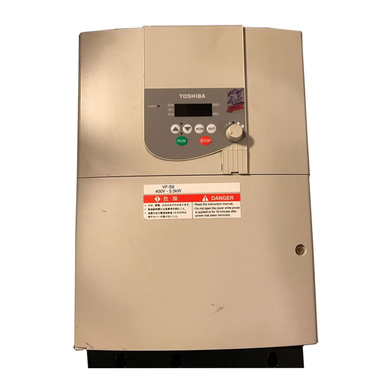
- Page 16 E6580757 Top warning label Note 1) Wiring hole Cooling fin Ventilation slits Name Plate [Bottom] [Side] Note 1) If ambient temperature is high, peel off this label. Removing label invalidates NEMA 1 rating unless enclosed in a cabinet. Example of the label.
- Page 17 E6580757 1.3.2 Main circuit and control circuit terminal boards Main circuit terminal board In case of the lug connector, cover the lug connector with insulated tube, or use the insulated lug con- nector. Screw size tightening torque M3 screw 0.8N m M4 screw 1.2N m M5 screw...
- Page 18 E6580757 VFS9S-2002PM ∼ 2015PM R/L1 S/L2 T/L3 M3 screw (2002 2007) M4 screw (2015) U/T1 V/T2 W/T3 Shorting-bar Grounding terminal M5 screw Screw hole of EMC plate VFS9-2022PM/2037PM VFS9-4007PL ∼ 4037PL R/L1 S/L2 T/L3 M4 screw U/T1 V/T2 W/T3 Shorting-bar Grounding terminal Screw hole of EMC plate M5 screw...
- Page 19 E6580757 VFS9-2055PL/2075PL 4055PL/4075PL M5 screw R/L1 S/L2 T/L3 U/T1 V/T2 W/T3 Shorting-bar Grounding terminal M5 screw Screw hole of EMC plate VFS9-2110PM/2150PM 4110PL/4150PL M6 screw R/L1 S/L2 T/L3 U/T1 V/T2 W/T3 Shorting-bar Grounding terminal M5 screw Screw hole of EMC plate In case of the lug connector, cover the lug connector with insulated tube, or use the insulated lug con- nector.
- Page 20 E6580757 Control circuit terminal board The control circuit terminal board is common to all equipment. M3 screw JP302 JP301A JP301 (0.5N m) Case of SINK M2 screw (0.25N m) JP301: Input JP301A: Output SOURCE FLA FLB FLC RY CC VIA VIB PP II FM F R RST S1 S2 S3 CC OUT P24 /FMC /SINK...
-
Page 21: Notes On The Application
If you want to run continuously low speed operations at rated torque, please use the VF motor made especially for Toshiba inverter. When operating in conjunction with a VF motor, you must change the inverter's motor overload protection level to "VF motor use ( )". - Page 22 E6580757 Extremely low loads and low inertia loads The motor may demonstrate instability such as abnormal vibrations or overcurrent trips at light loads of 50 percent or under of the load percentage, or when the load's inertia moment is extremely small. If that happens reduce the carrier frequency.
- Page 23 E6580757 ured in some other way, the overcurrent trip may be activated because of the locked rotor current when the brake goes into operation. Circuit configuration 2 uses low-speed signal RY to turn on and off the brake. Turning the brake on and off with a low-speed signal may be better in such applications as ele- vators.
- Page 24 E6580757 Circuit interrupting when two or more inverters are used on the same power line. (circuit interupting fuse) MCCB1 MCCB2 INV1 MCCB3 INV2 MCCBn+1 INVn Breaking of selected inverter There is no fuse in the inverter's main circuit. Thus, as the diagram above shows, when more than one inverter is used on the same power line, you must select interrupting characteristics so that only the MCCB2 will trip and the MCCB1 will not trip when a short occurs in the inverter (INV1).
- Page 25 1.Reduce PWM carrier frequency. The setting of PWM carrier frequency is done with the parameter 2.Use high frequency remedial products (Schneider Toshiba electric corporation: Esper Mighty Series) for earth leakage breakers. If you use equipment like this, there is no need to reduce the PWM carrier frequency.
- Page 26 E6580757 Remedies: 1.Use the electronic thermal built into the inverter. The setting of the electronic thermal is done using parameter 2.Reduce the inverter's PWM carrier frequency. However, that will increase the motor's magnetic noise. Use parameter for setting the PWM carrier frequency. 3.This can be improved by installing 0.1µ~0.5µF-1000V film capacitor to the input/output terminals of each phase in the thermal relay.
-
Page 27: Installation Environment
E6580757 1.4.4 Installation Installation environment The VF-S9 Inverter is an electronic control instrument. Take full consideration to installing it in the proper operating environment. Danger • Do not place any inflammable substances near the VF-S9 Inverter. If an accident occurs in which flame is emitted, this could lead to fire. - Page 28 If the VF-S9 Inverter is installed in a location that is subject to vibration, anti-vibration measures are required. Please consult with Toshiba about these measures. • If the VF-S9 Inverter is installed near any of the equipment listed below, provide measures to insure against errors in operation.
-
Page 29: Installation Location
Mandatory Operation cannot be stopped immediately by the inverter alone, thus risking an accident or injury. • All options used must be those specified by Toshiba. The use of any other option may result in an acci- dent. Warning •... - Page 30 If you are going to install the equipment in any area that presents a potential problem, please consult with Toshiba before doing so. Calorific values of the inverter and the required ventilation The energy loss when the inverter converts power from AC to DC and then back to AC is about 5 percent.
- Page 31 E6580757 • Install surge suppressor on any magnetic contactor and relay coils used around the inverter. • Install noise filters if necessary. • Install EMC plate (attached as standard) and shielded wires fit with the EMC plate. EMC plate Installing more than one unit in a cabinet If you are installing two or more inverters in one cabinet, pay attention to the following.
-
Page 32: Connection Equipment
E6580757 2. Connection equipment Danger • Never disassemble, modify or repair. This can result in electric shock, fire and injury. For repairs, call your sales agency. Disassembly prohibited • Don’t stick your fingers into openings such as cable wiring hole and cooling fan covers. This can result in electric shock or other injury. - Page 33 E6580757 Danger • Ground must be connected securely. If the ground is not securely connected, it could lead to electric shock or fire when a malfunction or cur- rent leak occurs. Be Grounded Warning • Do not attach devices with built-in capacitors (such as noise filters or surge absorber) to the output (motor side) terminal.
-
Page 34: Standard Connections
E6580757 Standard connections Danger • Do not connect input power to the output (motor side) terminals (U/T1, V/T2, W/T3). Connecting input power to the output could destroy the inverter or cause a fire. • Do not connect resistors to DC terminals (across PA-PC or across PO-PC). Prohibited It could cause a fire. -
Page 35: Standard Connection Diagram
E6580757 2.2.1 Standard connection diagram 1 - sink (common: CC) This diagram shows a standard wiring of the main circuit. DC reactor (DCL) *2 (option) Braking resistor Main circuit power supply (option) 200V class: single-phase 200 ~ 240V-50/60Hz three-phase 200 ~ 230V-50/60Hz 400V class: three-phase 380 ~ 500V-50/60Hz MCCB Motor... - Page 36 E6580757 2.2.2 Standard connection diagram 2 - source (common: P24) DC reactor (DCL) *2 (option) Main circuit power supply Braking resistor 200V class: single-phase 200 ~ 240V-50/60Hz (option) three-phase 200 ~ 230V-50/60Hz 400V class: three-phase 380 ~ 500V-50/60Hz MCCB Motor U/T1 R/L1 S/L2...
-
Page 37: Description Of Terminals
E6580757 Description of terminals 2.3.1 Main circuit terminals This diagram shows an example of wiring of the main circuit. Use options if necessary. Power supply and motor connections Power supply VF-S9 Power lines are Motor lines are connected to R., connected to U., S. -
Page 38: Main Circuit
E6580757 Main circuit Terminal symbol Terminal function Grounding terminal for connecting inverter case. 200V class: single-phase 200~240V-50/60Hz three-phase 200~230V-50/60Hz R/L1,S/L2,T/L3 400V class: three-phase 380~500V-50/60Hz * Single – phase series don’t have T/L3 terminal. Connect to a (three-phase induction) motor. U/T1,V/T2,W/T3 Connect to braking resistors PA,PB Change parameters... - Page 39 E6580757 Terminal Electrical Input/output Function Inverter internal circuits symbol specifications Common to Control circuit's common terminal Input/output +24V 10Vdc (permissible Output Analog input setting power output load current: 10mAdc) Multifunction programmable analog input. 4-20mA Standard default setting: 4(0)~20mAdc in- (internal imped- Input put and 0~50Hz (50Hz setting) or 0~60Hz ance: 400Ω)
- Page 40 E6580757 Terminal Electrical Input/output Function Inverter internal circuits symbol specifications SOURCE JP301 Open collector out- FUSE Multifunction programmable open collector put : 24Vdc-50mA output. Standard default settings detect Output and output speed reach signal output fre- *Sink-source quencies. switchable (JP301A) +24V 250Vac-2A (cosφ...
- Page 41 E6580757 Sink logic (negative common)/source logic (positive common) logic switching of input output terminals Current flowing out turns control input terminals on. These are called sink logic terminals (The end of Type - form : AN / WN). The general used method in Europe is source logic in which current flowing into the in- put terminal turns it on(The end of Type - form : WP).
- Page 42 E6580757 Logic switching/voltage-current output switching (jumper) Logic switching JP301 : Input, JP301A : Output Switch logic before wiring to inverter and without supplying power. If sink and source are switched when power is supplied first after logic switching or while power is being input to the inverter, that will destroy the inverter.
-
Page 43: Operations
E6580757 3. Operations Danger • Do not touch inverter terminals when electrical power is connected to the inverter even if the motor is stopped. Touching the inverter terminals while power is connected to it may result in electric shock. • Do not touch switches when the hands are wet and do not try to clean the inverter with a damp cloth. Prohibited Such practices may result in electric shock. -
Page 44: How To Operate The Vf-S9
E6580757 How to operate the VF-S9 Overview of how to operate the inverter with simple examples. Example 1 Setting the operation frequency using built-in potentiometer and run- ning and stopping using the operation panel. Wiring Motor MCCB R/L1 U/T1 S/L2 V/T2 Main circuit T/L3... - Page 45 E6580757 Example 2 Setting the operation frequency using the operation panel and run- ning and stopping using the operation panel. Wiring Motor MCCB R/L1 U/T1 S/L2 V/T2 Main circuit T/L3 W/T3 Control circuit Setting parameters Title Function Programmed value Command mode selection Frequency setting mode selection Operation Run/stop: Press the...
- Page 46 E6580757 Example 3 Setting the operation frequency using built-in potentiometer and run- ning and stopping using external signals. Wiring MCCB Motor R/L1 U/T1 S/L2 V/T2 Main circuit T/L3 W/T3 Forward rotation signal Control circuit Reverse rotation signal Common Parameter setting (default setting) Title Function Programmed value...
- Page 47 E6580757 Example 4 Operation frequency setting, running and stopping using external signals. Wiring Motor MCCB R/L1 U/T1 V/T2 S/L2 Main circuit T/L3 W/T3 Forward rotation signal Control circuit Reverse rotation signal Common Current signal: 4 ∼ 20mA Voltage signal: 0 ∼ 10V External potentiometer (or voltage signal to VIA-CC 0 ∼...
-
Page 48: Simplified Operation Of The Vf-S9
E6580757 Simplified Operation of the VF-S9 The procedures for setting operation frequency and the methods of operation can be selected from the following. (1) Run and stop using external signals to the terminal Run / stop board (2) Run and stop from the operation panel (1) Setting using external signals to the terminal board Frequency setting (0-10Vdc, 4-20mAdc) - Page 49 E6580757 3.2.1 How to start and stop (1) Start and stop using the operation panel keys ( Use the keys on the operation panel to start and stop the motor. RUN: Motor starts. STOP: Motor stops (slowdown stop). (2) Start and stop using external signals to the terminal board ( Use external signals to the inverter terminal board to start and stop the motor.
- Page 50 E6580757 (2) Setting the frequency using the operation panel ( Set the frequency from the operation panel. : Moves the frequency up : Moves the frequency down Example of operating a run from the panel Key operated LED display Operation Displays the operation frequency.
- Page 51 E6580757 Setting the frequency using input voltage (0~10V) voltage signal Setting frequency using voltage signals (0~10V). For more detailed information on adjustments, see 6.5. Voltage signal 0-10Vdc 50Hz or 60Hz Frequency * The input terminal VIB can be used in the same way. VIA and VIB are automatically switched by the default settings.
-
Page 52: Basic Vf-S9 Operations
E6580757 4. Basic VF-S9 operations The VF-S9 has the following three monitor modes. : The standard inverter mode. This mode is enabled when Standard monitor mode inverter power goes on. This mode is for monitoring the output frequency and setting the frequency desig- nated value. -
Page 53: How To Set Parameters
E6580757 Setting monitor mode How to set parameters The standard default parameters are programmed before the unit is shipped from the factory. Parameters can be divided into three major categories. Select the parameter to be changed or to be searched and retrieved. : The basic parameters that must be programmed be- Basic parameters fore the first use. - Page 54 E6580757 Basic parameters 4.1.1 How to set the basic parameters All of the basic parameters can be set by the same step procedures. [Steps in key entry for basic parameters] * The inverters are shipped from the Switches to the setting monitor mode. factory with set parameters by default.
-
Page 55: Extended
E6580757 4.1.2 How to set extended parameters The VF-S9 has extended parameters to allow you to make full use of its functions. All extended parameters are expressed with F and three digits. Basic parameter Press the key and the Press the MON key once and use the to select the parameter to be key and the key to select... - Page 56 E6580757 Example of parameter setting The steps in setting are as follows. Example of changing the dynamic braking selection from 0 to 1. Key operated LED display Operation Displays the operation frequency (operation stopped). (When stan- dard monitor display selection is set to [operation fre- quency])
- Page 57 E6580757 How to search and reprogram parameters The operations of search and resetting of parameters are as follows. Key operated LED display Operation Displays the operation frequency (operation stopped). (When stan- dard monitor display selection is set to [operation fre- quency]) Press the MON key to display the first basic parameter (automatic acceleration/deceleration).
-
Page 58: Setup Parameters
E6580757 Setup parameters 4.1.4 How to program setup parameters When the standard parameter is set to (standard default setting), the setup parameter is displayed. Setting the setup parameter enable to operate. The setup parameter selects either 50Hz or 60Hz for the base motor frequency. Set this in line with the specifications of the motor. - Page 59 E6580757 4.1.5 Parameters that cannot be changed while running For reasons of safety, the following parameters have been set up so that they cannot be reprogrammed while the inverter is running. Basic parameters (Automatic acceleration/deceleration) (Automatic torque boost) (Automatic environment setting) (Automatic function setting) , and (Command mode selection)
- Page 60 E6580757 Steps for returning all parameters to standard default setting Key operated LED display Operation Displays the operation frequency (perform during operation stopped). Press the MON key to display the first basic parameter (automatic acceleration/deceleration). Press the key or the key to change to Pressing the ENTER key displays the programmed parameters.
-
Page 61: Basic Parameters
E6580757 5. Basic parameters Before you operate the inverter, the parameters that you must first program are the basic parameters. Setting acceleration/deceleration time : Automatic acceleration/deceleration : Acceleration time 1 : Deceleration time 1 • Function 1) For acceleration time , program the time that it takes for the inverter output frequency to go from 0Hz to maximum frequency 2) For deceleration time... - Page 62 E6580757 [Parameter setting] Title Function Adjustment range Default setting 0: Disabled (manual) Automatic acceleration/deceleration 1: Optimum rate 2: Minimum rate When automatically setting acceleration/deceleration time, always change the acceleration/deceleration time so that it conforms with the load. For inverters that requires a fixed acceleration/deceleration time, use the manual settings ( Setting acceleration/deceleration time ( ) in conformance with mean load allows optimum...
-
Page 63: Increasing Starting Torque
E6580757 If the programmed value is shorter than the optimum acceleration/deceleration time determined by load conditions, overcurrent stall or overvoltage stall function may make the acceleration/deceleration time longer than the programmed time. If an even shorter acceleration/deceleration time is programmed, there may be an overcurrent trip or overvoltage trip for inverter protection. - Page 64 E6580757 Key operated LED display Operation Press the key to change the parameter to 1 (sensorless vector control + auto-tuning). Press the ENTER key to save the changed parameter. the parameter are alternately displayed. Note 1: Setting V/F control selection (sensorless vector control) provides the same characteristics as (auto-tuning) is set to 2.
-
Page 65: Setting Environmental Protection
E6580757 Setting environmental protection : Automatic environment setting • Function This automatically programs all parameters related to inverter environmental protection (auto-restart or ride-through control after momentary power failure, supply voltage correction, acceleration/deceleration S- pattern). This parameter is especially suitable for wind force or hydraulic machinery such as fans and pumps Note: Do not use this parameter for equipment such as transporters, since it is dangerous to operate automatically such equipment after temporary stops. - Page 66 E6580757 Automatically programmed functions and parameter set values Default setting 1: Coast stop 2: 3-wire opera- 3: External input 4: 4-20mA current tion UP/DOWN set- input operation ting 1: Operation 2: Potentiometer 2: Potentiometer 2: Potentiometer 0: Terminal board panel 1: Operation 0: Terminal board 0: Terminal board...
-
Page 67: Selection Of Operation Mode
E6580757 minal, and DOWN (frequency down signal input from external contact) are assigred to the S2 and CLR (fre- quency up/down clear signal input from external contact) are assigned to the S3 terminals respectively. Frequencies can be changed by input to the S1 and S2 terminals. 4-20mA current input operation Used for setting frequencies with 4-20mA current input. -
Page 68: Meter Setting And Adjustment
E6580757 [Setting values] Frequency setting commands are entered by external signals. (VIA/VIB termi- Terminal board nals: 0-10Vdc or II terminal: 4-20mAdc) Operation Press the key or the key on either the operation panel or the ex- panel pansion panel (optional) to set frequency. Internal The internal potentiometer to the inverter is used for setting frequencies. - Page 69 E6580757 Adjustment scale with meter adjustment parameter Connect meters as shown below. <Frequency meter> <Ammeter> Meter: ammeter Meter: frequency meter = 1) (default setting) The reading of the The reading of the frequency meter frequency meter will fluctuate during will fluctuate during scale adjustment.
-
Page 70: Standard Default Setting
E6580757 [Example of how to adjustment the FM terminal frequency meter] Use the meter's adjustment screw to pre-adjust zero-point. Key operated LED display Operation Displays the operation frequency. (When standard monitor display selec- tion is set to [operation frequency] Press the MON key to display the first basic parameter (automatic acceleration/deceleration) . -
Page 71: Selecting Forward And Reverse Runs (Operation Panel Only
E6580757 This function will be displayed as during reading on the right. This previous setting is displayed. cannot be set during the inverter operating. Always stop the inverter first and then program. [Setting values] Default setting Setting will return all parameters to the standard values that were programmed at the factory. When 3 is programmed, will be displayed for a short time after setting and will then be erased and displayed the original indication (... -
Page 72: Maximum Frequency
E6580757 Short across the R-CC terminals: reverse rotation * Reverse rotation is valid if short across the F-CC terminals and R-CC terminals at the same time. This function is valid only when is set to 1 (operation panel). Maximum frequency : Maximum frequency •... -
Page 73: Base Frequency
E6580757 Upper limit Lower-limit Output frequency (Hz) Output frequency (Hz) frequency frequency Frequency setting signal Frequency setting signal Frequencies that go The output frequency higher than will cannot be set at less not be output. than Parameter setting Title Function Adjustment range Setting after setup 0.5 ∼... -
Page 74: Selecting Control Mode
E6580757 5.12 Selecting control mode : V/F control mode selection • Function With VF-S9, the V/F controls shown below can be selected V/F constant Variable torque Automatic torque boost Sensorless vector control Automatic energy-saving (*1) "Automatic torque boost " parameter can automatically set this parameter and auto-tuning at a time. - Page 75 E6580757 1) Constant torque characteristics (general method of use) Setting of V/F control mode selection (V/F constant) This is applied to loads with equipment like conveyors and cranes that require the same torque at low speeds as at rated speeds. Base frequency voltage Output frequency (Hz) Base frequency...
-
Page 76: Increasing Starting Torque
(V/F constant) and increase torque manually. Motor constant must be set If the motor you are using is a 4P Toshiba standard motor and if it has the same capacity as the inverter, there is basically no need to set the motor constant. - Page 77 Motor constant must be set The motor you are using is a 4P Toshiba standard motor and if it has the same capacity as the inverter, there is basically no need to set the motor constant. There are two procedures for setting the motor constant.
-
Page 78: Manual Torque Boost-Increasing Torque At Low Speeds
E6580757 5.13 Manual torque boost - increasing torque at low speeds : Torque boost 1 • Function If torque is inadequate at low speeds, increase torque by raising the torque boost rate with this parame- ter. Base frequency voltage Output frequency (Hz) Base frequency [Parameters] Title... - Page 79 E6580757 Parameter setting Title Function Adjustment range Default setting Setting Overload Overload value protection stall × Standard × × motor Electronic thermal protection × characteristics selection × VF motor (special × × motor) × Motor electronic thermal pro- 10 ∼ 100 (%) tection level 1 : valid, ×...
- Page 80 E6580757 Setting of electronic thermal protection characteristics selection Setting value Overload protection Overload stall × × × × : valid, × : invalid Setting of motor electronic thermal protection level 1 If the capacity of the motor is smaller than the capacity of the inverter, or the rated current of the motor is smaller than the rated current of the inverter, adjust the electronic thermal protection level 1 that it fits the motor's rated current.
- Page 81 E6580757 [Using a VF motor (motor for use with inverter)] Setting selection of electronic thermal protection characteristics Setting value Overload protection Overload stall × × × × : valid, × : invalid A VF motor (a motor for use with an inverter) can be used in lower frequency ranges than the general- purpose motor, but if that frequency is extremely low, the effects of cooling on the motor will deteriorate.
-
Page 82: Preset-Speed Operation (Speed In 15 Steps
E6580757 2) Inverter over load characteristics Set to protect the inverter unit. Cannot be changed or turned off by parameter setting. If the inverter overload trip function ( ) is activated frequently, this can be improved by adjusting the stall operation level downward or increasing the acceleration time or deceleration time Inverter overload... - Page 83 E6580757 Preset-speed frequency setting Set the speed (frequency) of the number of steps necessary. Setting from speed 1 to speed 7 Title Function Adjustment range Default setting ∼ Preset-speed operation frequencies ∼ (Hz) Setting from speed 8 to speed 15 Title Function Adjustment range...
- Page 84 E6580757 Using other speed commands with preset-speed command Command mode selection 0 : Terminal board 1 : Operation panel 0 : Terminal 0 : Terminal Frequency setting 1 : Operation 1 : Operation board 2 : Potentiometer board 2 : Potentiometer mode selection panel panel...
-
Page 85: Extended Parameters
E6580757 6. Extended parameters Extended parameters are provided for sophisticated operation, fine adjustment and other special purposes. Modify pa- rameter settings as required. See Section 11, Table of extended parameters. Input/output parameters 6.1.1 Low-speed signal : Low-speed signal output frequency •... - Page 86 E6580757 [Connection diagram for sink logic] [Incase of relay] • Output terminal setting Output of the low-speed signal (ON signal) between the RY and RC terminals is the factory default set- ting of the output terminal selection parameter. This setting must be changed to invert the polarity of the signal.
- Page 87 E6580757 Output frequency [Hz] Designated frequency Designated frequency − Designated frequency Designated frequency attainment signal Time [s] P24-OUT (Default setting) RY-RC FLA-FLC-FLB Speed attainment set frequency: Inverted 6.1.3 Output of set frequency speed reach signal : Speed reach setting frequency : Speed reach detection band •...
-
Page 88: Input Signal Selection
E6580757 1) If the detection band value + the set frequency is less than the designated fre- quency Output frequency [Hz] Time [sec] Set frequency speed reach detection signal RY-RC P24-OUT FLA/FLC/FLB Set frequency speed reach signal: Inverted Input signal selection 6.2.1 Changing the standby signal function : ST (standby) signal selection... - Page 89 E6580757 1) Standby on when ST is on Motor speed Use this setting if an ST (standby) Coast stop terminal is required. * The ST terminal is not assigned as standard default setting. Assign the ST function to an F-CC idle input terminal by the input terminal selection.
-
Page 90: Terminal Function Selection
E6580757 Parameter setting Title Function Adjustment range Default setting 0: Standard setting (reset on when RST-CC on to off) RST signal selection 1: Activated by turning RST off (reset on when RST-CC off to on) Terminal function selection 6.3.1 Keeping an input terminal function always active (ON) : Always-active function selection •... - Page 91 E6580757 Setting of contact input terminal function Terminal Title Function Adjustment range Default setting symbol 0 (Without assigned Always-active function selection function) Input terminal selection 1 (F) 2 (Forward run) 0-51 Input terminal selection 2 (R) 3 (Reverse run) (See Section 11 Input terminal selection 3 (RST) 10 (Reset) table of input termi-...
- Page 92 E6580757 Inverter Programmable controller External +24V power supply Inverter internal Fuse blowout +24V power detection circuit supply Fuse 3) Sink logic/source logic input Sink logic/source logic (input/output terminal logic) switching is possible. See Section 2.3 for further details. Example of application ... Three-wire operation START Run: Press START.
-
Page 93: Modifying Output Terminal Functions
E6580757 6.3.3 Modifying output terminal functions : Output terminal selection 1 (RY-RC) : Output terminal selection 2 (OUT) : Output terminal selection 3 (FLA/B/C) Use the above parameters to send various signals from the inverter to external equipment. Up to 30 functions can be used by setting special parameters for the RY-RC, OUT, and FL (FLA, FLB, FLC) terminals on the control terminal board. -
Page 94: Basic Parameters 2
E6580757 Basic parameters 2 6.4.1 Switching motor characteristics via terminal input : Base frequency 2 : Torque boost 2 : Motor electronic-thermal protection level 2 • Function Use the above parameters to switch the operation of two motors with a single inverter and to select motor V/F characteristics (two types) according to the particular needs or operation mode. -
Page 95: Frequency Priority Selection
E6580757 Frequency priority selection 6.5.1 Using a frequency command according to the particular situation : Frequency setting mode selection : Frequency priority selection • Function Use the above parameters to select the command to be used for frequency setting, and to assign priority to one of the two types of input frequency reference signals. - Page 96 E6580757 2) Automatic frequency switching 2 Frequency priority selection parameter = 0: Terminal board is selected. First priority is assigned to analog input terminals VIB, and second priority to analog input terminals VIA/II. When the input to VIB with first priority becomes null, control will be switched automatically to VIA/II with sec- ond priority.
-
Page 97: Setting Frequency Command Characteristics
E6580757 6.5.2 Setting frequency command characteristics : VIA/II input point 1 setting : VIA/II input point 1 frequency : VIA/II input point 2 setting : VIA/II input point 2 frequency : VIB input point 1 setting (Frequency UP response time) : VIB input point 1 frequency (Frequency UP step width) : VIB input point 2 setting (Frequency DOWN response time) : VIB input point 2 frequency (Frequency DOWN step width) - Page 98 E6580757 1) 0-10Vdc voltage input adjustment (VIA, VIB) VIA, VIB terminals • The output frequency with respect to the voltage input is 50 or 60 (Hz) adjusted according to the selected reference point. • Gradient and bias can be set easily.
- Page 99 E6580757 Set parameters as follows to adjust the output frequency up or down almost in synchronization with the adjustment by the panel frequency command: ] ≤ ( setting time) ] ≤ ( setting time) <<Sample sequence diagram 1: Adjustment with continuous signals>> RUN command Incrementing (UP) signal...
- Page 100 E6580757 <<Sample sequence diagram 2: Adjustment with pulse signals>> RUN command Incrementing (UP) signal Decrementing (DOWN)signal Set frequency clearing signal Upper limit frequency Simultaneous input • If input clearing signal and decrementing signal at the same time, clearing signal is allowed. •...
-
Page 101: Operation Frequency
E6580757 Operation frequency 6.6.1 Starting frequency : Starting frequency setting • Function The frequency set with the parameter is put out immediately on completion of frequency set- ting. Use the parameter when a delay in response of starting torque according to the accelera- tion/deceleration time is probably affecting operation. -
Page 102: Dc Braking
E6580757 6.6.2 Run/stop control with frequency setting signals : Operation starting frequency : Operation starting frequency hysterisis • Function The Run/stop of operation can be controlled simply with frequency setting signals. [Parameter setting] Title Function Adjustment range Default setting 0.0 ∼ Operation starting frequency (Hz) 0.0 ∼... -
Page 103: Jog Run Mode
E6580757 [Parameter setting] Title Function Adjustment range Default setting 0.0 ∼ DC braking starting frequency (Hz) 0.0 ∼ 100 (%) DC braking current 30.0 0.0 ∼ 20.0 (sec) DC braking time Output frequency [Hz] Set frequency DC braking DC braking starting frequency Time [sec] Output current [A] DC braking current... - Page 104 E6580757 [Parameter setting] Title Function Adjustment range Default setting 0.0 ∼ 20.0 (Hz) Jog run frequency 0: Slowdown stop Jog run stopping pattern 1: Coast stop 2: DC braking <Examples of jog run> RST-CC (JOG) ON + F-CC ON: Forward jog run RST-CC (JOG) ON + R-CC ON: Reverse jog run ( Normal operation frequency signal input + F-CC ON: Forward run ) ( Normal operation frequency signal input + R-CC ON: Reverse run )
-
Page 105: Jump Frequency-Jumping Resonant Frequencies
E6580757 Jump frequency - jumping resonant frequencies : Jump frequency 1 : Jumping width 1 : Jump frequency 2 : Jumping width 2 : Jump frequency 3 : Jumping width 3 • Function Resonance due to the natural frequency of the mechanical system can be avoided by jumping the reso- nant frequency during operation. -
Page 106: Preset-Speed Operation Frequency 8
E6580757 6.10 Preset-speed operation frequency 8 to 15 ∼ : Preset-speed operation frequency 8 to 15 See Section 5.15 for details. 6.11 PWM carrier frequency : PWM carrier frequency : Random mode • Function 1) The F300 parameter allows the tone of the magnetic noise from the motor to be changed by switching the PWM carrier frequency. -
Page 107: Trip-Less Intensification
E6580757 [400V Class] 480V or less More than 480V Carrier frequency Carrier frequency VFS9- 4kHz or less 12kHz 15kHz 16.5kHz 4kHz or less 12kHz 15kHz 16.5kHz 4007PL 2.3A 2.1A 2.1A 2.1A 2.1A 1.9A 1.9A 1.9A 4015PL 4.1A 3.7A 3.3A 3.1A 3.8A 3.4A 3.1A... - Page 108 E6580757 Title Function Adjustment range Default setting 0: Disabled 1: At auto-restart after momentary stop 2: When turning ST-CC on or off 3: At auto-restart or when turning ST-CC on or off Auto-restart control 4: Motion of DC braking at start-up (at auto- selection restart after momentary stop) 5: Motion of DC braking at start-up (when turning...
- Page 109 E6580757 Application!! • A waiting time of 200 to 1,000msec is preset to allow the residual voltage in the motor to decrease to a certain level during restart. For this reason, the start-up takes more time than usual. • Use this function when operating a system with one motor connected to one inverter. This function may not operate properly in a system configuration with multiple motors connected to one inverter.
-
Page 110: Retry Function
E6580757 6.12.3 Retry function : Retry selection (Selecting the number of times the motor is to be restarted automatically) Warning • Do not go near the motor in alarm-stop status when the retry function is selected. The motor may suddenly restart, which could result in injury. •... - Page 111 E6580757 creases below a predetermined level. In the event of overheating-caused tripping ( ), re-tripping may result unless the internal temperature decreases below a predetermined level, since the internal temperature detection function of the inverter works. Even when trip retention selection parameter is set to "...
- Page 112 E6580757 1) Connecting an external braking resistor (optional) Separate-type optional resistor (with thermal fuse) External braking resistor (optional) MCCB Motor R/L1 U/T1 Three-phase main circuits S/L2 V/T2 Power supply T/L3 W/T3 Inverter Connecting thermal relays and an external braking resistor External braking resistor (optional) TH-R...
- Page 113 E6580757 2) Setting the braking resistor operation rate Calculate the braking resistor operation rate as follows: Braking resistor operating time 1-cycle operation time T Operation rate: Tr/T * 100 (%ED) 3) Optional dynamic braking resistors (Optional braking resistors for higher frequen- cies of regenerative braking are also available) Optional dynamic braking resistors are listed below.
-
Page 114: Avoiding Overvoltage Tripping
E6580757 4) Minimum resistances of connectable braking resistors The minimum allowable resistance values of the externally connectable braking resistors are listed in the ta- ble below. Do not connect braking resistors with smaller resultant resistances than the listed minimum allowable resis- tance values. - Page 115 E6580757 6.12.6 Output voltage adjustment/Supply voltage correction : Output voltage adjustment (Base frequency voltage) : Supply voltage correction • Function Output voltage adjustment (Base frequency voltage) parameter adjusts the voltage corresponding to the base frequency 1 so that no voltage exceeding the set value is put out.
- Page 116 E6580757 [0: Supply voltage uncorrected, [1: Supply voltage corrected, output voltage limited] output voltage limited] Input voltage × Input voltage Rated voltage High High Input voltage Output frequency Output frequency * The above applies when V/F control mode selection parameter is set to "0"...
- Page 117 E6580757 6.12.7 Conducting PI control : Proportional/integral control (PI control) : Proportional gain : Integral gain • Function These parameters provide various types of process control, such as maintaining constant air quan- tity, flow rates and pressures, by input of feedback signals from the detector. [Parameter setting] Title Function...
- Page 118 E6580757 2) Types of PI control interfaces Process quantity input data (frequency) and feedback input data can be combined as follows for the PI con- trol of the VF-S9: Process quantity input data (frequency setting) Feedback input data Setting method Frequency setting mode External analog input (1) Internal potentiometer setting...
- Page 119 E6580757 (I-gain adjustment parameter) This parameter adjusts the integral gain level during PI control. Any deviations remaining unremoved during proportional action are cleared to zero (residual deviation offset function). A larger I-gain adjustment value reduces residual deviations. Too large an adjustment value, however, results in an unstable event such as hunting.
-
Page 120: Setting Motor Constants
E6580757 6.13 Setting motor constants : Auto-tuning : Slip frequency : Motor primary constant : Motor secondary constant : Motor excitation constant : Magnification of load inertial moment : Rated capacity ratio of motor to inverter To use vector control, automatic torque boost and automatic energy-saving, motor constant setting (motor tuning) is required. - Page 121 E6580757 [Parameter setting] Title Function Adjustment range Default setting 0: Auto-tuning disabled (Use of internal parameters) ∼ Auto-tuning 1: Application of individual settings of 2: Auto tuning enabled (returns to "1" after auto-tuning) to " ". to " " if the motor capacity is one size smaller than the applicable rated capacity of the inverter. Precautions on auto-tuning (1) Conduct auto-tuning only after the motor has been connected and operation completely stopped.
- Page 122 E6580757 Setting procedure Adjust the following parameters: ∼ : Select " " to set the motor constant independently using the parameters. : Set the slip frequency for the motor. A higher slip frequency reduces motor slipping correspond- ingly. (The slip frequency can be set on the basis of test records of the motor.) : Adjust the primary resistive component of the motor.
-
Page 123: Acceleration/Deceleration Patterns And Acceleration/Deceleration 2
E6580757 6.14 Acceleration/deceleration patterns and acceleration/deceleration 2 : Acceleration time 1 : Deceleration time 1 : Acceleration time 2 : Deceleration time 2 : Acceleration/deceleration 1 pattern : Acceleration/deceleration 2 pattern : Acceleration/deceleration pattern selection (1 or 2) : Acceleration/deceleration 1 and 2 switching frequency •... - Page 124 E6580757 Acceleration/deceleration patterns Linear acceleration/deceleration A general acceleration/ deceleration pat- Output frequency tern. This pattern can usually be used. [Hz] Maximum frequency Time [sec] S-pattern acceleration/deceleration 1 Output frequency Select this pattern to accelerate/decelerate [Hz] the motor rapidly to a high-speed region Maximum with an output frequency of 60Hz or more frequency...
- Page 125 E6580757 Switching to acceleration/deceleration Selection using parameters Output frequency [Hz] Time [sec] Acceleration/deceleration time 1 is initially set as the default. Acceleration/deceleration time 2 can be selected by changing the setting of the parameter. Switching by frequencies - Switching the acceleration/deceleration time automatically at the frequency setting of Output frequency [Hz] Set frequency...
-
Page 126: Protection Functions
E6580757 Switching using external terminals - Switching the acceleration/deceleration time via external termi- nals Output frequency [Hz] AD2 switching Time [sec] (1) Acceleration at the gradient (3) Deceleration at the gradient corresponding to acceleration corresponding to deceleration time time (2) Acceleration at the gradient (4) Deceleration at the gradient corresponding to acceleration corresponding to deceleration... - Page 127 E6580757 6.15.2 Setting current stall : Stall prevention level • Function This parameter reduces the output frequency by activating a current stall prevention function against a current exceeding the -specified level. Parameter setting Title Function Adjustment range Default setting 10 ∼ 199 (%), 200: Disabled Stall prevention level [Display during an alarm status]...
- Page 128 E6580757 6.15.4 External input trip stop mode selection : External input trip stop mode selection : Emergency DC braking time • Function These parameters set the method of stopping the inverter in external trip stop mode. When the inverter is stopped, the trip detection function (" "...
-
Page 129: Output Phase Failure Detection
E6580757 2) Emergency stopping from the operation panel Emergency stopping from the operation panel is possible by pressing the STOP key on the panel twice while the inverter is not in the panel control mode. (1) Press the STOP key ......" "... - Page 130 E6580757 6.15.6 Input phase failure detection : Input phase failure detection mode selection • Function This parameter detects inverter input Phase failure. If the abnormal voltage status of main circuit ca- pacitor persists for few minutes or more, the tripping function and the FL relay will be activated. At the same time, the trip information will also displayed.
- Page 131 E6580757 Title Function Adjustment range Default setting 0: Disabled Small current trip selection 1: Enabled 0 ∼ 100 (%) Small current (trip/alarm) detection current 0 ∼ 255 (s) Small current (trip/alarm) detection time 6.15.8 Over-torque trip : Over-torque trip selection : Over-torque (trip/alarm) level : Over-torque (trip/alarm) detection time : Over-torque (trip/alarm) level hysterisis...
- Page 132 E6580757 1) Output terminal function : 12 (OT) Over–torque detection (No trip) Over-torque detection signal Less than Torque current Time(s) When setting to (Trip), trip after over-torque detection time setting of 2) Output terminal function : 20 (POT) Over-torque detection pre-alarm (No trip) Over-torque detection pre-alarm signal...
-
Page 133: Undervoltage Trip
E6580757 6.15.9 Undervoltage trip : Undervoltage trip selection • Function This parameter is used for selecting the control mode when an undervoltage is detected. Trip infor- mation is displayed as “ “. (Disabled)..The inverter is stopped. However, it is not tripped (FL relay deactivated). The inverter is stopped when the voltage does not exceed 70% or less of its rating. -
Page 134: Operation Panel Parameter
E6580757 Examples of setting 6.16 Operation panel parameter 6.16.1 Prohibition of change of parameter settings : Prohibition of change of parameter settings • Function This parameter specifies whether parameter setting is changeable or not. Setting methods : Permitted_____Modification of during operation is prohibited (default setting). Modification of during operation is also prohibited. - Page 135 E6580757 [Parameter setting] Title Function Adjustment range Default setting 0: Permitted cannot be modified during operation) Prohibition of change of 1: Prohibited parameter settings 2: Permitted can be modified during op- eration) Resetting method Only the parameter is designed so that its setting can be modified even if " " (prohibited) is se- lected.
- Page 136 E6580757 1) Display in percentage terms Display in amperes/volts Output current: Output current: Input (DC) voltage: Input (DC) voltage: (vale of changing to AC) An example of setting for displaying the motor speed or load speed to either " " or " ".
- Page 137 E6580757 converts the following parameter settings: • A display Current monitor display Motor electronic thermal protection level 1/2 DC braking current Stall prevention level Small current detection level • V display Voltage monitor display Torque boost 1/2 • Free unit Frequency monitor display ∼...
-
Page 138: Communication Function (Common Serial
E6580757 6.17 Communication function (Common serial) : Data transfer speed : Parity : Inverter number : Communication error trip time Refer to the COMMUNICATIONS EQUIPMENT USER'S MANUAL for details. • Function The VFS9 Series allows a data communication network to be constructed for exchanging data between a host computer or controller (referred to collectively as the computer) and the inverter by connecting an optional RS232C or RS485 communication conversion unit. - Page 139 E6580757 Communication function parameters (Common serial options) The data transfer speed, parity type, inverter number, and communication error trip time can be set/edited by operation panel operation or communication function. Title Function Adjustment range Default setting 0: 1200bps 1: 2400bps Data transfer speed 2: 4800bps 3: 9600bps...
- Page 140 E6580757 Example of connection for RS485-communication <Independent communication> Perform computer-inverter connection as follows to send operation frequency commands from the host computer to inverter No. 3: Wiring Data (host → INV) Host computer Response data (INV → host) "Given away": Only the inverter with the selected inverter number conducts data processing. All other inverters, even if they have received the data, give it away and stand by to receive the next data.
-
Page 141: Applied Operation
E6580757 7. Applied operation Setting the operation frequency Applied operation can be performed by selecting the inverter frequency setting, using the basic parameter (frequency setting mode selection) and the extended parameter (frequency priority selection). (1) Internal potentiometer setting (2) Operation panel key setting STOP STOP Enter the number with the operation panel... - Page 142 E6580757 (3) External potentiometer setting (4) Input voltage setting(0 to 10 Vdc) STOP STOP Voltage signal (VIA/II) (VIA/II) Use the parameters for this setting. To use VIB, set at . (5) Input current setting(4 to 20 mAdc) (6) External contact UP/DOWN STOP STOP S1 (UP)
- Page 143 E6580757 (7) Preset-speed setting (8) Voltage/current switching STOP STOP S1(FCHG) Current signal Voltage signal : 7-speed run : 8-speed run (Automatic switching) To select 7-speed run, use the terminals S1 to S3. To select 15-speed run, add the terminal S4. (Forced switching of FCHG.
- Page 144 E6580757 (11) Switching between analog setting and (12) Switching between analog setting and terminal set- preset-speed setting ting from the operation panel RST(PNL/T STOP STOP Current signal Current signal Voltage signal Voltage signal To switch to preset-speed setting, use the external terminals S1 to S4. To switch to VIA/II or VIB setting, use the ex- ternal PNL/TB.
-
Page 145: Setting The Operation Mode
E6580757 Setting the operation mode Applied operation can be performed by selecting the operation mode. To set the operation mode, use the basic parameter (command mode selection) and the input terminal selection parameter. Operation panel operation Terminal board operation STOP STOP (Operation panel) (Terminal board) - Page 146 E6580757 Three-wire operation / Self-holding of operation signal Note 1 : In case of three - wire operation, set to set to Select one input terminal, and set to HD (op- eration holding). (S1 terminal) set to : HD. STOP Note 2 : Enable to turn the input terminal on at power S1 (HD) Note 3 : Enable to turn the terminal F and R on at HD :...
- Page 147 E6580757 Operation from an external input device Switching from an external input device to the ter- minal board STOP STOP S1 (SC/LC) Serial I/F Serial I/F Priority is given to an external input device Remote control can be switched forcefully to when the remote command fa00h 15-bit is local control from the external SC/LC by setting set at 1.
-
Page 148: Monitoring The Operation Status
E6580757 8. Monitoring the operation status Status monitor mode In this mode, you can monitor the operation status of the inverter. To display the operation status during normal operation: Press the key twice. Setting procedure (eg. operation at 60Hz) Communi- Item displayed Description cation No. - Page 149 E6580757 (Continued) Communi- Item displayed Description operated display cation No. CPU version FE08 The version of the CPU is displayed. Memory version FE09 The version of the memory mounted is displayed. Past trip 1 (displayed alternately at 0.5-sec. inter- Note 4 Past trip 1 FE10 vals)
-
Page 150: Display Of Trip Information
E6580757 Display of trip information If the inverter trips, an error code is displayed to suggest the cause. In the status monitor mode, all trip records are retained. Display of trip information Communi- Error code Description cation No. Overcurrent during acceleration Overcurrent during deceleration Overcurrent during operation Armature-side overcurrent during start-up... - Page 151 E6580757 Communi- Error code Description cation No. No error (Note) Past trip records (trip records retained or trips that occurred in the past) can be called up. (Refer to 8.1 "Status monitor mode" for the call-up procedure.) (*) Strictly speaking, this code is not an error code; this code is displayed to show the absence of error when the past trip monitor mode is selected.
- Page 152 E6580757 (Continued) Communi- Item displayed Description operated display cation No. Memory version FE09 The version of the memory mounted is displayed. Past trip 1 (displayed alternately at 0.5-sec. inter- Past trip 1 FE10 vals) Past trip 2 (displayed alternately at 0.5-sec. inter- Past trip 2 FE11 vals)
-
Page 153: Taking Measures To Satisfy The Ce/Ul Directive
The CE mark must be put on every final product that includes an inverter(s) and a motor(s). The VF-S9 series of inverters complies with the EMC directive if an EMI filter recommended by Toshiba is connected to it and wiring is carried out correctly. -
Page 154: Measures To Satisfy The Emc Directive
E6580757 Table 1 EMC standards Category Subcategory General standard Test standard and level Radiation noise EN 55011, Group 1, Class A Emission EN50081-2 Transmission noise EN 55011, Group 1, Class A Static discharge EN 61000-4-2 Radioactive radio-frequency magnetic EN 61000-4-3 contactor field First transient burst EN 61000-4-4... - Page 155 E6580757 Single-phase 200V class Combination of inverter and filter Inverter Filter for class A Filter for class B compliance compliance VFS9S-2002PL With a built-in filter EMFS2010AZ VFS9S-2004PL With a built-in filter EMFS2010AZ VFS9S-2007PL With a built-in filter EMFS2010AZ VFS9S-2015PL With a built-in filter EMFS2016CZ VFS9S-2022PL With a built-in filter...
- Page 156 9.1.3 About the low-voltage directive The low-voltage directive provides for the safety of machines and systems. All Toshiba inverters are CE-marked in accordance with the standard EN 50178 specified by the low-voltage directive, and can therefore be installed in machines or systems and imported without problem to European countries.
-
Page 157: Peripheral Devices
E6580757 10. Peripheral devices Danger • When using switchgear for the inverter, it must be installed in a cabinet. Failure to do so can lead to risk of electric shock and can result in death or serious injury. Danger Mandatory •... - Page 158 Note 2: Be sure to attach a surge killer to the exciting coil of the relay and the magnetic contactor. Selection of surge killers for Toshiba magnetic contactors 200V class: Surge absorbing units are optionally available for Toshiba C11J to C65J, or Model SS-2 for C50J and C65J 400V class: For the operation and control circuits, regulate the voltage at 200V or less with a step-down transformer.
-
Page 159: Installation Of A Magnetic Contactor
E6580757 10.2 Installation of a magnetic contactor If using the inverter without installing a magnetic contactor (MC) in the primary circuit, use an MCCB (with a power cutoff device) to open the primary circuit when the inverter protective circuit is activated. If using a braking resistor or braking resistor unit, install a magnetic contactor (MC) or non-fuse circuit breaker with a power cutoff device to the power supply of the inverter, so that the power circuit opens when the failure detection relay (FL) in the inverter or the external overload relay is activated. -
Page 160: Installation Of An Overload Relay
• When using a motor with a current rating different to that of the corresponding Toshiba general-purpose motor •... - Page 161 E6580757 Optional external devices Device Function and purpose Input AC reactor Used to improve the input power factor, reduce the harmonics, and suppress external surge on the inverter power source side. Install when the power capacity is 500 kVA or more and 10 times or more than the inverter capacity or when a distorted wave genera- tion source such as a thyristor unit or a large-capacity inverter is connected in the same distribution system.
- Page 162 (Model: CBVR-7B1) Application control unit AP Series is available to enable various types of application control functions when com- (15) bined with an inverter. Contact your Toshiba representative for further information. Table for selection of optional external devices Radio noise Motor-end...
- Page 163 E6580757 Devices External dimensions and connections Input AC re- actor VF-S9 VF-S9 (ACL) Input AC reactor Terminal box with cover Power supply VF-S9S VF-S9S Input AC reactor Power supply 4-φF holes Fig.A FIg.B Approx. Dimensions (mm) Type Rating Inverter type Terminals weight (kg)
- Page 164 E6580757 Devices External dimensions and connections DC reactor (DCL) Terminal box with cover Name plate Name plate 4.4 × 6 slotted hole(DCLS-2002) 4.4 × 6 slotted hole(DCL-2007) Fig.A Fig.B Terminal box with cover Name plate DC reactor Power supply 4-φ7 Fig.C Rated Approx.
- Page 165 E6580757 Devices External dimensions and connections Foot- mounted W1(Mounting dimension) noise filter VF-S9 VF-S9 Filter Dimensions (mm) Rated Type current Inverter type Remarks Approx. weight (kg) VFS9S-2002PL ∼ 2007PL EMFS2010AZ EMC : class B compliance VFS9-2002PM ∼ 2015PM EMF2011BZ EMC : class A compliance EMFS2016CZ VFS9-2015PL EMF4006CZ...
- Page 166 E6580757 Devices External dimensions and connections Braking resistor φ4.2 VF-S9 Power supply Braking resister Fig.A Fig.C 4-φ5 holes VF-S9 Wire opening Power supply Braking resister Connect to operation circuit Earth terminal (M5) Fig.D Fig.B Dimensions (mm) Diagram/ Approx. Model Rating Inverter type Connection weight(kg)
- Page 167 E6580757 Devices External dimensions and connections Parameter Extension panel Parameter writer Communication Converter RS485/RS232C writer Exten- sion panel Note) Dimensions of extension panel are Note) Following is RS485 unit. Dimensions of RS232C unit are same as RS485 same as following drawing, but the following, but RS232C doesn’t have a connector.
-
Page 168: Table Of Parameters And Data
E6580757 11. Table of parameters and data 11.1 User parameters *1 : The end of type – form depend AN – WN : 60Hz WP : 50Hz *2 : Model depend (See section 11 page K-6) Title Function Unit Minimum Adjustment range Default User... -
Page 169: Extended Parameters
E6580757 Title Communication Function Unit Minimum Adjustment range Default User Reference setting unit setting setting 0008 Forward/reverse 0: Forward run run selection 1: Reverse run (Operation panel) 0009 Acceleration 0.1-3600 10.0 time 1 0010 Deceleration 0.1-3600 10.0 time 1 0011 Maximum 30.0-400 80.0... - Page 170 E6580757 Title Communication Function Unit Minimum Adjustment range Default User Reference setting unit setting setting 0110 Always-active 0-51 6.3.1 function selection 0111 Input terminal 0-51 (F) 6.3.2 selection 1 (F) 0112 Input terminal 0-51 (R) 6.3.2 selection 2 (R) 0113 Input terminal 0-51 (RST) 6.3.2...
- Page 171 E6580757 Title Communication Function Unit Minimum Adjustment range Default User Reference setting unit setting setting 0213 VIB input point 2 0-400 6.5.2 frequency Frequency DOWN 0.0-400.0 step width *5 0240 Starting frequency 0.5-10.0 6.6.1 setting 0241 Operation starting 0.0- 6.6.2 frequency 0242 Operation starting...
- Page 172 E6580757 • Operation mode parameters Title Communication Function Unit Minimum Adjustment range Default User Reference setting unit setting setting 0300 PWM carrier 2.0-16.5 12.0 6.11 frequency 0301 Auto-restart 0: Disabled 6.12.1 control selection 1: At auto-restart after momentary stop 2: When turning ST-CC on or off 3: At auto-restart or when turning ST-CC on or off 4: Motion of DC braking at start-up...
- Page 173 E6580757 • Torque boost parameters Title Communication Function Unit Minimum Adjustment range Default User Reference setting unit setting setting 0400 Auto-tuning 0: Auto-tuning disabled (use of inter- 6.13 nal parameters) 1: Application of individual settings of 2: Auto-tuning enabled (returns to 1 after auto-tuning) 0401 Slip frequency...
- Page 174 E6580757 Title Communication Function Unit Minimum Adjustment range Default User Reference setting unit setting setting 0608 Input phase failure 0: Disabled 6.15.6 detection mode 1: Enabled selection 0610 Small current trip 0: Disabled 6.15.7 selection 1: Enabled 0611 Small current 0-100 6.15.7 (trip/alarm)
- Page 175 E6580757 Default settings by inverter rating Inverter model Torque boost Slip frequency Motor primary Motor secon- Motor excitation constant dary constant constant VFS9S-2002PL 6.0% 3.0Hz VFS9S-2004PL 6.0% 3.0Hz VFS9S-2007PL 6.0% 3.0Hz VFS9S-2015PL 6.0% 2.7Hz VFS9S-2022PL 5.0% 2.7Hz VFS9-2002PM 6.0% 3.0Hz VFS9-2004PM 6.0% 3.0Hz...
- Page 176 E6580757 Table of input terminal functions (2/3) Function Code Function Action ST+RST Combination of standby and reset commands ON: Simultaneous input from ST and RST ST+PNL/TB Combination of standby and operation ON: Simultaneous input from ST and PNL/TB panel/terminal board switching F+JOG Combination of forward run and jog run ON: Simultaneous input from F and JOG...
- Page 177 E6580757 Table of input terminal functions (3/3) Function Code Function Action EXTN Inversion of trip stop command from external de- OFF: -trip stop vice Thermal trip stop signal input from external device trip stop Inversion of thermal trip stop command from ex- OFF: trip stop ternal device...
- Page 178 E6580757 Table of output terminal functions (2/2) Function Code Function Action RUNN Inversion of RUN/STOP Inversion of RUN setting OL pre-alarm ON: 50% or more of calculated value of overload protection level OFF: Less than 50% of calculated value of over- load protection level POLN Inversion of OL pre-alarm...
- Page 179 E6580757 Order of precedence of combined functions XX: Impossible combination, X: Invalid, +: Valid under some conditions, O: Valid, @: Priority Function No. / Function Forward run command Reverse run command Jog run command (18/19) Acceleration/deceleration 2 selection Preset-speed run commands 1 to 4 Reset command Trip stop command from external input device...
-
Page 180: Specifications
E6580757 12. Specifications 12.1 Models and their standard specifications Standard specifications Item Specification Input voltage 3-phase 200V Applicable motor (kW) 0.75 Type VFS9- Form 2002PM 2004PM 2007PM 2015PM 2022PM 2037PM 2055PL 2075PL 2110PM 2150PM Capacity (kVA) Note 1) Rated output current 11.0 17.5 27.5... - Page 181 E6580757 Item Specification Control system Sinusoidal PWM control Rated output voltage Adjustable within a range of 100 to 120% of the corrected supply voltage (200/400V) (Unadjustable to any voltage higher than the input voltage). Output frequency range 0.5 to 400Hz, default setting: 0.5 to 80Hz, maximum frequency: 30 to 400Hz. Minimum setting steps of 0.1Hz: operation panel setting, 0.2Hz: analog input (when the max.
-
Page 182: Outside Dimensions And Mass
E6580757 12.2 Outside dimensions and mass Outside dimensions and mass Applicable motor Dimensions (mm) Approx. weight Input voltage Type Drawing (kW) (kg) VFS9S-2002PL VFS9S-2004PL 1-phase 200V 0.75 VFS9S-2007PL VFS9S-2015PL VFS9S-2022PL VFS9-2002PM VFS9-2004PM 0.75 VFS9-2007PM VFS9-2015PM VFS9-2022PM 3-phase 200V VFS9-2037PM VFS9-2055PL VFS9-2075PL VFS9-2110PM 15.8... -
Page 183: Outline Drawing
E6580757 Outline drawing ¿5 (Mounting dimension) R2.5 (Mounting dimension) VF S9 VF S9 * VFS9 2002PM and plate plate 4 M4 4 M4 VFS9S 2002PL don’t have fan. Fig. A Fig. B (Mounting dimension) VF S9 plate 4 M4 Fig. C... -
Page 184: Before Making A Service Call-Trip Information And Remedies
When a problem arises, diagnose it in accordance with the following table. If it is found that replacement of parts is required or the problem cannot be solved by any remedy described in the table, contact your Toshiba dealer. [Trip information]... - Page 185 E6580757 (Continued) Communication Error code Problem Possible causes Remedies • The input voltage fluctuates abnormally. • Insert a suitable input reactor. Overvoltage during constant-speed op- (1) The power supply has a capacity of eration 200kVA or more. (2) A power factor improvement capacitor is opened or closed.
- Page 186 E6580757 (Continued) Communication Error code Problem Possible causes Remedies • The output current falls to the low-current • Enable Small-current opera- (low-current detection pa- tion trip detection level during operation. rameter). • Check whether the detection level is set properly to the system. •...
- Page 187 E6580757 (Continued overleaf) Error code Problem Possible causes Remedies • DC braking in process • Normal if the message disappears after DC braking several tens of seconds. (See Note 2.) • Parameters are being initialized to default • Normal if the message disappears after a Parameters in the process of initializa- values.
-
Page 188: Restoring The Inverter From A Trip
E6580757 13.2 Restoring the inverter from a trip Do not reset the inverter when tripped because of a failure or error before eliminating the cause. Resetting the tripped inverter before eliminating the problem causes it to trip again. The inverter can be restored from a trip by any of the following operations: (1) By turning off the power (Keep the inverter off until the LED turns off.) Note) Refer to 6.15.3 (inverter trip retention selection ) for details. -
Page 189: If The Motor Does Not Run While No Trip Message Is Displayed
E6580757 13.3 If the motor does not run while no trip message is displayed ... If the motor does not run while no trip message is displayed, follow these steps to track down the cause. YES : The motor does not run. Is the 7-segment LED Check the power supply and the MCCB. -
Page 190: How To Determine The Causes Of Other Problems
E6580757 13.4 How to determine the causes of other problems The following table provides a listing of other problems, their possible causes and remedies. Problems Causes and remedies • Invert the phases of the output terminals U, V and W. The motor runs in the •... - Page 191 E6580757 How to cope with parameter setting-related problems • You can search for all reset parameters and change their settings. If you forget parameters which have been reset * Refer to 4.1.4 for details. • You can return all parameters which have been reset to their default settings. If you want to return all reset parameters to their * Refer to 4.1.6 for details.
-
Page 192: Inspection And Maintenance
E6580757 14. Inspection and maintenance Danger • The equipment must be inspected every day. If the equipment is not inspected and maintained, errors and malfunctions may not be discovered which could lead to accidents. • Before inspection, perform the following steps. (1) Shut off all input power to the inverter. -
Page 193: Periodical Inspection
E6580757 Check points 1. Something unusual in the installation environment 2. Something unusual in the cooling system 3. Unusual vibration or noise 4. Overheating or discoloration 5. Unusual odor 6. Unusual motor vibration, noise or overheating 14.2 Periodical inspection Make a periodical inspection at intervals of 3 or 6 months depending on the operating conditions. Danger •... - Page 194 E6580757 (Note) Before an insulation test, always disconnect all cables from the main circuit terminal board and test the inverter separately from other equipment. 500V insulation tester (megger) 7. Never test the inverter for pressure. A pressure test may cause damage to its components. 8.
-
Page 195: Making A Call For Servicing
Note) The life of a part greatly varies depending on the environment of use. 14.3 Making a call for servicing For the Toshiba service network, refer to the back cover of this instruction manual. If defective conditions are en- countered, please contact the Toshiba service section in charge via your Toshiba dealer. -
Page 196: Warranty
Failure or damage caused by the use of the inverter for any purpose or application other than the intended one All expenses incurred by Toshiba for on-site services shall be charged to the customer, unless a service contract is signed beforehand between the customer and Toshiba, in which case the service contract has priority over this war-... -
Page 197: Disposal Of The Inverter
E6580757 16. Disposal of the inverter Warning • If you throw away the inverter, have it done by a specialist in industry waste disposal*. If you throw away the inverter by yourself, this can result in explosion of capacitor or produce noxious gases, resulting in injury. - Page 198 INDUSTRIAL ELECTRONIC PRODUCT DEPARTMENT 2121, NAO, ASAHI-CHO, MIE-GUN, MIE, 510-8521 JAPAN Tel: 593-76-6032 For further information, please contact your nearest Toshiba Liaison Representative or International Operations - Producer Goods. The data given in this brochure are subject to change without notice. 2000-X...
Need help?
Do you have a question about the TOSVERT VF-S9 and is the answer not in the manual?
Questions and answers