Toshiba TOSVERT VF-FS1 Instruction Manual
Hide thumbs
Also See for TOSVERT VF-FS1:
- Instruction manual (247 pages) ,
- Function manual (38 pages) ,
- Function manual (20 pages)
Advertisement
Quick Links
Thank you for purchasing a Toshiba "totally-enclosed box type TOSVERT VF-FS1 series inverter."
This Manual gives a supplementary explanation of some items referred to in the instruction manual E6581381 included with
the product. Please read this manual carefully along with the instruction manual E6581381.
Please see to it that this manual is supplied to the inverter's end user, along with the instruction manual E6581381.
■Safety precautions
Before reading this manual, please read the following instructions in addition to "I. Safety Precautions," of the instruction
manual E6581381.
■General Operation
•
Mandatory
■Transportation
•
Mandatory
•
Instruction Manual (Supplementary)
Totally-Enclosed Box Type Inverter
TOSVERT VF-FS1
- To set makers -
Circuit boards are exposed when the front cover is removed. So do not detach the front
cover when the inverter is energized or within 10 minutes after power is turned off. Doing so
could result in electric shock.
In case of up to 7.5kW-inverter unit, when handling the inverter unit, hold it by both the sides
firmly. If you hold it by the fins at the upper and lower parts, you could get injured.
For a model designed 11kW or larger, carry it at least in a twosome, or it could fall and
cause you to get an injury.
Danger
Warning
1
E6581471①
Advertisement

Related Manuals for Toshiba TOSVERT VF-FS1


Summary of Contents for Toshiba TOSVERT VF-FS1
- Page 1 Totally-Enclosed Box Type Inverter TOSVERT VF-FS1 Thank you for purchasing a Toshiba “totally-enclosed box type TOSVERT VF-FS1 series inverter.” This Manual gives a supplementary explanation of some items referred to in the instruction manual E6581381 included with the product. Please read this manual carefully along with the instruction manual E6581381.
-
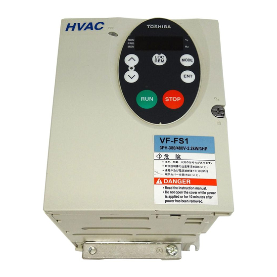
Page 2: Exterior Features
E6581471 ■Exterior Features Side view CHARGE lamp Indicates that high voltage is still present within the inverter. Do not open the cover while this is lit. Devices Remarks Operation panel Equipped with ▲,▼, MODE and ENT keys used to set parameters, RUN and STOP used to drive the motor, LOC/REM used to change local and remote, a 7-segment LED and a CHARGE lamp. - Page 3 E6581471 ■Power circuit terminal In case of the lug connector, cover the lug connector with insulated tube, or use the insulated lug connector. The input terminal board of VFFS1-4110PDE – 4185PDE has terminals of a cable pinch type. And, the main circuit terminal board of VFFS1-4220PLE –...
- Page 4 E6581471 VFFS1-4007PLE-4022PLE VFFS1-4007PDE-4022PDE Output terminal M4 Input terminal M4 Output terminal M4 Input terminal M4 Plus / Minus screw Plus / Minus screw Plus / Minus screw Plus / Minus screw Grounding terminal M4 Grounding terminal M5 Grounding terminal M5 Plus / Minus screw Grounding terminal M4 Plus / Minus screw...
- Page 5 E6581471 VFFS1-4075PLE / 4075PDE Input terminal M5 Output terminal M5 Plus / Minus screw Plus / Minus screw Grounding terminal M5 Grounding terminal M5 Plus / Minus screw Plus / Minus screw VFFS1-4110PLE-4150PLE VFFS1-4110PDE-4150PDE Output terminal M5 Plus / Minus screw Input terminal M4 Minus screw Input terminal M5...
- Page 6 E6581471 VFFS1-4185PLE VFFS1-4185PDE Input terminal M5 Output terminal M6 Minus screw Input terminal M6 Plus / Minus screw Output terminal M6 Plus / Minus screw Plus / Minus screw Grounding terminal M5 Grounding terminal Grounding terminal M5 Plus / Minus screw Hexagon nut Plus / Minus screw VFFS1-4220PLE-4450PLE...
- Page 7 E6581471 VFFS1-4550PLE-4750PLE VFFS1-4550PDE-4750PDE Output terminal M16 Input terminal M12 Input terminal M16 Hexagon socket set screw Hexagon socket set screw Hexagon socket set screw Output terminal M16 Hexagon socket set screw Grounding terminal M16 Grounding terminal M16 Grounding terminal M8 Grounding terminal M8 Hexagon socket set screw Hexagon socket set screw...
- Page 8 E6581471 ■How to open the front and control circuit terminal(0.75kW – 7.5kW) Charge lamp screw screw Control circuit terminal board screw screw Main circuit terminal board screw Power supply : PE, R, S, T screw Motor output :U, V, W, PE Internal DC section :PA/+, PC/- Grounding screw How to remove the front cover...
- Page 9 E6581471 ■How to open the front and control circuit terminal(11kW – 75kW) Charge lamp screw screw screw Control circuit terminal board screw screw screw Main circuit terminal board Power supply : PE, R, S, T Motor output :U, V, W, PE Internal DC section :PA/+, PC/- screw screw...
- Page 10 E6581471 ■Wiring diagram 0.75kW – 7.5kW (1) Input power cable (2) Output cable (3) Control cable (4) Optinal communications device interconnect cable(option) (PLE -type) (PDE-type) PLE-type:EN61800-3, 1st Environment, C2(up to 5.5kW) or C3 PDE-type:EN61800-3, 1st Environment, C1 11kW – 18.5kW (1) Input power cable (2) Output cable (3) Control cable...
- Page 11 E6581471 22kW – 75kW (1) Input power cable (2) Output cable (3) Control cable (4) Optinal communications device interconnect cable(option) (PLE -type) (PDE-type) PLE-type:EN61800-3, 1st Environment, C3 PDE-type:EN61800-3, 1st Environment, C1 Caution • Circuit boards are exposed when the front cover is removed. Since high voltages are applied to some parts of the circuit board, read Section 2.1, “Cautions on wiring,”...
- Page 12 E6581471 ■Grounding capacitor disconnecting switch (1): Common with PLE and PDE (2): Only PDE-type (3): Only PLE-type PLE-type:EN61800-3, 1st Environment, C2 or C3 PDE-type:EN61800-3, 1st Environment, C1 7.5kW 0.75kW-5.5kW 11kW-18.5kW 22kW-30kW...
- Page 13 E6581471 (1): Common with PLE and PDE (2): Only PDE-type (3): Only PLE-type PLE-type:EN61800-3, 1st Environment, C2 or C3 PDE-type:EN61800-3, 1st Environment, C1 37kW-45kW 55kW-75kW...
- Page 14 E6581471 ■Measures to satisfy the EMC directive Inverters are tested in this combination below. Transmission noise Transmission noise EN61800-3, 1st Environment, C2 EN61800-3, 2nd Environment, C3 Applicable filters Length of motor Applicable filters Length of motor connecting connecting cable (m) cable (m) VFFS1-4007PLE With a built-in filter...
-
Page 15: Outside Dimensions
E6581471 ■Outside dimensions Applica Outside dimensions (mm) Mass Inverter type Outline Cable port (kg) Motor (kW) 0.75 VFFS1-4007PLE VFFS1-4007PDE φ16.5×2 VFFS1-4015PLE 192.3 φ20.5×1 VFFS1-4015PDE φ25.5×2 VFFS1-4022PLE VFFS1-4022PDE VFFS1-4037PLE VFFS1-4037PDE φ16.5×2 VFFS1-4055PLE 208.3 φ20.5×1 VFFS1-4055PDE φ25.5×2 VFFS1-4075PLE VFFS1-4075PDE VFFS1-4110PLE 21.0 φ16.5×1 VFFS1-4110PDE 25.5 295.3... - Page 16 E6581471...
- Page 17 E6581471 C D...
- Page 18 E6581471 E...
- Page 19 E6581471...
- Page 20 E6581471...
- Page 21 E6581471 ■Specifications Item specification Voltage class 3-phase 400V class Applicable motor (kW) 0.75 Voltage class Model VFFS1- number 3-phase 400V VFFS1- 4007PLE 4015PLE 4022PLE 4037PLE 4055PLE 4075PLE class 4007PDE 4015PDE 4022PDE 4037PDE 4055PDE 4075PDE Capacity (kVA) Note 1: 12.2 Output current (A) 3-phase 12.0 16.0...
- Page 22 E6581471 Item specification Voltage class 3-phase 400V class Applicable motor (kW) 18.5 Voltage class Model VFFS1- number 3-phase 400V VFFS1- 4110PLE 4150PLE 4185PLE 4220PLE 4300PLE 4370PLE class 4110PDE 4150PDE 4185PDE 4220PDE 4300PDE 4370PDE Capacity (kVA) Note 1: 17.1 23.2 28.2 33.2 44.6 52.0...
- Page 23 E6581471 Item specification Voltage class 3-phase 400V class Applicable motor (kW) Voltage Model VFFS1- class number 3-phase VFFS1- 4450PLE 4550PLE 4750PLE 400V class 4750PDE 4550PDE 4750PDE Capacity Note 1: 61.9 76.3 105.3 (kVA) Output 3-phase 400V 94.0 116.0 160.0 current (A) class (75.2) (104.4)
- Page 24 E6581471 Note1) Capacity is calculated at 440V for the 400V models. Note2) The values between parentheses refer to output currents at PWM carrier frequencies of over 12kHz. When installing the inverter where the ambient temperature will rise above 40degree, use the inverter with the rated output reduced.
- Page 25 E6581471 Output current Output current Output current 100% 100% 100% Switching frequency (kHz) Switching frequency (kHz) Switching frequency (kHz) 30kW 18.5kW 22kW Output current Output current Output current 100% 100% 100% Switching frequency (kHz) Switching frequency (kHz) Switching frequency (kHz) 37kW 45kW 55kW...
- Page 26 E6581471 Note3) The maximum output voltage is equal to the input supply voltage. Note4) ±10% when the inverter is operated continuously (under a load of 100%). Note5) IP54-compliant structures refer to structures that protect the contents from dust and harmful effects of water that drops from every direction.
Need help?
Do you have a question about the TOSVERT VF-FS1 and is the answer not in the manual?
Questions and answers