
Related Manuals for Redline AN-80i

Summary of Contents for Redline AN-80i
- Page 1 AN-80i PTP System User Manual 70-00072-01-01-DRAFT Proprietary Redline Communications © 2006 October 18, 2006 Page 1 of 60...
-
Page 2: Copyright Information
Additionally, Redline makes no representations or warranties, either expressed or implied, regarding the contents of this product. Redline Communications shall not be liable for any misuse regarding this product. The information in this document is subject to change without notice. -
Page 3: Table Of Contents
System Configuration Screen..............21 General....................22 Wireless Configuration ................ 23 Controls ....................26 System Password Screen ............... 27 AN-80i Product Options Screen .............. 29 Entering the Options Key..............29 Upload Software ..................30 SNMP Settings Screen................31 3.9.1 Change SNMP Community ..............32 3.9.2... - Page 4 Upgrade....................46 4.2.12 User ..................... 46 Diagnostics and Troubleshooting ............47 Factory Default Settings ................47 Procedure to Reset AN-80i IP Address ........... 48 5.2.1 Procedure .................... 48 Testing and Saving System Parameters ..........49 Web Interface ..................49 CLI Interface ..................49 Troubleshooting the Web Interface ............
- Page 5 Table 23: Diag. - Status Codes ................51 Table 24: Diag. - System Log Messages ............52 Table 25: Spec. - AN-80i Technical Specifications ..........55 Table 26: Spec. - AN-80i PoE Specifications ............56 Table 27: Spec. - Antenna Power Specifications ..........56 70-00072-01-01-DRAFT Proprietary Redline Communications ©...
- Page 6 LIST OF FIGURES Figure 1: Intro - AN-80i Components ..............11 Figure 2: Intro - AN-80i with Integrated Antenna..........12 Figure 3: Intro - Indoor Power-over-Ethernet (PoE) Module ....... 13 Figure 4: Web - Login Screen ................14 Figure 5: Web - System Menu................
-
Page 7: Important Safety & Service Notices
Customer equipment including personal computers, routers, etc., must only be connected to the 'INPUT' port on the PoE unit. Only the outdoors Ethernet interface cable to the AN-80i can be safely connected to the 'OUTPUT' connector. -
Page 8: Important Warning Symbols
2. Locate the serial numbers and record these on your registration card for future reference. Use the space below to affix serial number stickers. Also, record the MAC address located on the AN-80i. Product Information Use the following table to record important system information:... -
Page 9: Lightning Protection
80i as practical. The grounding wire should be connected to the same termination point used for the tower or mast. 4. Provide direct grounding from the AN-80i, the mounting bracket, the antenna, and the Ethernet cable surge protection to the same ground bus on the building. -
Page 10: Fcc Notice
6. AN-80i must be installed in compliance with relevant articles in National Electrical Code-NEC (and equivalent Canadian Code-CEC) including referenced articles 725, 800 and 810 in NEC. 7. RF coaxial cable connecting an antenna to AN-80i must comply with the local electrical code. 70-00072-01-01-DRAFT Proprietary Redline Communications ©... -
Page 11: System Overview
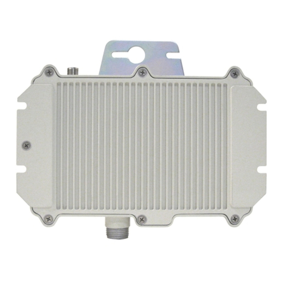
Automatic Transmitter Power Control (ATPC) to automatically achieve and maintain optimum performance. The AN-80i outdoor unit is housed in a weatherproof aluminum alloy case. The outdoor unit can be used with a selection of available external antennas. When equipped with a narrow beam antenna, the AN-80i supports long-range operations of over 50 miles (80 km) in clear line of sight (LOS) conditions. -
Page 12: Ethernet Port
AN-80i user manual Each wireless link requires two AN-80i units. One AN-80i is configured as the PTP Master and controls the wireless link; this function is transparent to all Ethernet operations. The master AN-80i uses a scheduled request/grant mechanism to arbitrate requests for bandwidth from the remote unit -- providing non contention-based traffic with predictable transmission characteristics. -
Page 13: Antenna Alignment
Customer equipment including personal computers, routers, etc., must only be connected to the 'INPUT' port on the PoE unit. Only the outdoors Ethernet interface cable to the AN-80i can be safely connected to the 'OUTPUT' connector. -
Page 14: Web Interface
Figure 4: Web - Login Screen Login to the AN-80i using your user name and password. See Table 5: Web - Default System Users on page 28 for the factory default usernames and passwords. If the IP address, username and/or password have been modified since installation, contact the network administrator to determine the current settings. -
Page 15: System Menu
Figure 5: Web - System Menu The administrator (admin) has unrestricted access to all screens. All other users have viewing access only. See 3.6: System Password Screen on page 27 for details. 70-00072-01-01-DRAFT Proprietary Redline Communications © 2006 October 18, 2006 Page 15 of 60... -
Page 16: System Information
Hardware Version: Displays the hardware version of the AN-80i. System Mode: The system designated as master establishes and manages the bi- directional data link with a remote end AN-80i. Only one system in a wireless link must be set for Master mode. -
Page 17: Ethernet
AN-80i user manual Ethernet Ethernet MAC Address: Hardware (MAC) address of this AN-80i. This address is also recorded on a label on the AN-80i chassis. IP Address: User-assigned IP address of this AN-80i. IP Subnet Mask: User assigned IP subnet mask. -
Page 18: System Status
Software Version: Displays the software version in use. RF Link Established: Status for the wireless link connection. Yes - RF link has been successfully established with the remote-end AN-80i. No - RF link has not been established with the remote-end AN-80i. -
Page 19: Ethernet Lan Statistics
Ethernet MAC Address: System hardware address. This is also printed on a label affixed to the AN-80i. IP Address: User-assigned IP address of the AN-80i. IP Subnet Mask: User-assigned IP subnet mask. Default Gateway Address: User-assigned IP for the default router or gateway. -
Page 20: System Logs Screen
Click System Log in the menu to view the system activity and error messages recorded by the AN-80i. Figure 7: Web - System Log Messages See section 5.6: System Log Messages on page 52 for detailed descriptions of each log message. -
Page 21: System Configuration Screen
Configure System in the menu to view and adjust configuration settings for general system identification, Ethernet, and the wireless interface. Figure 8: Web - PTP Configuration Screen 70-00072-01-01-DRAFT Proprietary Redline Communications © 2006 October 18, 2006 Page 21 of 60... -
Page 22: General
AN-80i user manual General System Name: Enter the name for this AN-80i. The name can be any combination of letters and numbers. System Details: Enter additional descriptive details about this AN-80i. The description can be any combination of letters and numbers. -
Page 23: Wireless Configuration
Auto scan: Check this box to enable the AN-80i PTP Slave to automatically scan available channels and locate the current operating frequency of the AN-80i PTP Master. Tx Power [dBm]: Enter the transmit power level (dBm). This setting is for the transceiver output only. - Page 24 AN-80i to monitor the received signal and request that the remote system adjustment its transmit level for optimum performance. The ATPC feature must be enabled on both AN-80i units. Adaptive Modulation: Check this box to enable the AN-80i to automatically adjust the transmission modulation and code settings to achieve the highest UBR that will operate with a packet error rate (PER at layer 2) of less than 1x10e-6.
-
Page 25: Table 3: Web - Ethernet Status Indication
Reset AN-80i IP Address on page 48. System Mode: The PTP Master establishes and manages the bi-directional data link with a remote end AN-80i. Only one system in a wireless link must be set for PTP Master mode. PTP Master: This unit begins transmitting automatically; sends poll messages to the remote AN-80i, and negotiates the wireless link. -
Page 26: Controls
During the 'test' period, you may click the Save button at any time to save this configuration permanently (also terminating the five minute timer). If the Save button is not selected during the five minute test period, the AN-80i is rebooted and the previously saved settings are reloaded. -
Page 27: System Password Screen
This screen allows the operator to modify the system passwords. The AN-80i supports two groups of users: admin and user. See Table 5: Web - Default System Users on 28 for the factory default login values. See Table 4: Web - Screens and User Access on page 28 for permissions associated with each group. -
Page 28: Table 4: Web - Screens And User Access
Important There must always be at least on 'administrator' account active on the system. If all accounts are changed to 'user' the AN-80i can not be managed. 70-00072-01-01-DRAFT Proprietary Redline Communications © 2006 October 18, 2006 Page 28 of 60... -
Page 29: An-80I Product Options Screen
AN-80i with the matching MAC address. For each new AN-80i received from the factory, the options key is provided on a printed label supplied with the unit. You will be unable to establish a wireless until the product options key is typed into the Options Key field on this screen. -
Page 30: Upload Software
Slower network connections may take longer -- do not interrupt the transfer process. 4. When the file transfer is complete, the AN-80i verifies the integrity of the new software file. If errors were introduced during the transfer process, the software file is rejected and a warning message is registered in the event log, and you must repeat the upload. -
Page 31: Snmp Settings Screen
MIB an to change enabled fields within the MIB. When the SNMP Agent in the AN-80i detects an error condition, a special message known as a trap can be sent (if enabled). A Trap Host is an IP system/server that is set up to receive SNMP trap messages. -
Page 32: Change Snmp Community
Community Name: Enter or modify the SNMP community name for this entry. Access Rights: Select the access permissions for this entry. None: Deny read and write permission for this entry. 70-00072-01-01-DRAFT Proprietary Redline Communications © 2006 October 18, 2006 Page 32 of 60... -
Page 33: Change Snmp Trap Configuration
This action does not permanently save changes. To save changes to the SNMP trap settings you must click the Save Traps button in the SNMP Configuration screen. 70-00072-01-01-DRAFT Proprietary Redline Communications © 2006 October 18, 2006 Page 33 of 60... -
Page 34: Spectrum Sweep
The transmitter of the PTP Master AN-80i is automatically disabled during the spectrum scan. If the scan is being performed from a PTP Slave AN-80i, the transmitter on the remote AN-80i for this link should be disabled during the test. -
Page 35: Table 6: Web - Performing A Spectrum Sweep
System Mode: Use Web/CLI to disable radio on remote-end. Use 'test' PTP Master function to save and remote end will restore radio operation automatically after 5 minutes. 70-00072-01-01-DRAFT Proprietary Redline Communications © 2006 October 18, 2006 Page 35 of 60... -
Page 36: Cli Interface
4.1.1 Connecting via Telnet To connect to the AN-80i, open a Telnet session to the IP address of the AN-80i. On a Windows™ PC, open the Run command and type 'telnet' followed by the IP address of the AN-80i. When the command prompt screen appears, login to the AN-80i. -
Page 37: Common Commands
Terminate this telnet session. May be entered from any mode. CLI Commands The following table lists all AN-80i commands available from root mode (default mode when you login). All commands are case-sensitive. Use the following general format for all commands: command <Enter>... -
Page 38: Chgver
AN-80i user manual 4.2.1 Chgver Use the chgver command to change the software version to loaded when you reboot the AN-80i. Also see the Get command 'swver'. Table 9: CLI - chgver Command Parameter/Description chgver Enter this command to toggle between software versions. The setting will alternate between the two banks of memory (no parameters). -
Page 39: Reset
Reboot the AN-80i. There are no parameters associated with this command. reboot <Enter> 4.2.4 Reset Use the reset command to set all AN-80i statistics values to zero. Table 12: CLI - reset Command Parameter/Description reset stats: Reset the AN-80i statistics counters. - Page 40 Table 14: CLI - set atpc: Enable or disable the ATPC function. Both AN-80i units monitor Rx signal and automatically adjust the Tx level of the transmitting system to optimize system performance. The ATPC feature must be enabled on both ends of the link.
- Page 41 10hd - 100Base-T Half Duplex 100fd - 100Base-T Full Duplex flowctrl: Enable or disable the flow control function. The Flow control feature enables the AN-80i to request other Ethernet devices to pause transmission during busy periods. off - Disable on - Enable gateway: Enter the IP address of the default gateway on this segment.
-
Page 42: Show
The system designated as master establishes and manages the bi-directional data link with a remote end AN-80i. Only one system in a wireless link must be set for Master mode. ptpmaster - This unit begins transmitting automatically; sending poll messages to locate the remote AN-80i and then negotiates to establish the wireless link. - Page 43 = 23 radio = On snmp = On Wireless Cfg: rffreq = 5840.0 snmp: Show SNMP settings: SNMP Enabled: Traps Enabled: Trap Link Up/Down Enabled: Off 70-00072-01-01-DRAFT Proprietary Redline Communications © 2006 October 18, 2006 Page 43 of 60...
- Page 44 = On wtxpktr = 42317 rffreq = 5840.0 wtxpktd = 928 calcdst = 0 Km txpower = 16 chwidth = 40 MHz ubrate = 54 Mbps (7) rfstatus 70-00072-01-01-DRAFT Proprietary Redline Communications © 2006 October 18, 2006 Page 44 of 60...
-
Page 45: Snmpcommunity
Use the test command to load the current edited (but not permanently saved) configuration settings. Table 18: CLI - test Command Parameter/Description test config - AN-80i configuration settings test config <Enter> 70-00072-01-01-DRAFT Proprietary Redline Communications © 2006 October 18, 2006 Page 45 of 60... -
Page 46: 4.2.11 Upgrade
If you do not 'save' the configuration within five minutes, the AN- 80i reboots -- discarding the unsaved settings and loading the last saved configuration. 4.2.11 Upgrade Use the upgrade command to upload a new software binary file to the AN-80i. Table 19: CLI - upgrade Command Description upgrade ipaddr: Enter the IP address of the FTP server. -
Page 47: Diagnostics And Troubleshooting
If the system is not operating correctly after applying the suggestions in this section, please contact your local Redline representative. Include the model name and serial number of the system in your communications. -
Page 48: Procedure To Reset An-80I Ip Address
Procedure to Reset AN-80i IP Address The AN-80i features a method to gain access to the CLI commands for a unit where the IP address, username, and/or password is unknown. This method requires local access to the AN-80i PoE power adapter, the capability to power- cycle the AN-80i, a PC with a telnet client, and an Ethernet cable. -
Page 49: Testing And Saving System Parameters
AN-80i load the current settings displayed in the configuration screen. The AN-80i will operate with these settings for a period of five minutes. During the test period you may click the Save button at any time to save this configuration permanently (also terminating the five minute timer). -
Page 50: Troubleshooting The Web Interface
IP of 192.168.25.3 and a subnet mask of 255.255.255.0. If the correct IP address of the AN-80i cannot be determined, it is recommended to perform the IP recovery procedure. See 5.2: Procedure to Reset AN-80i IP Address on page 48. -
Page 51: Status Codes
AN-80i user manual Status Codes The AN-80i reports the following conditions using the Status Code field. See 3.3.1: System Status on page 18. Table 23: Diag. - Status Codes Error Type Error # Description (Hexadecimal) Tx Power 0x0001 Power output is less than 10 dBm. -
Page 52: System Log Messages
RAM. Values were not saved. 1009 - Network Configuration: OK, The loaded network configuration is valid. 2009 - Network Configuration: ERROR, Error detected in the current network configuration. 70-00072-01-01-DRAFT Proprietary Redline Communications © 2006 October 18, 2006 Page 52 of 60... - Page 53 1029 - HTTP(User Mgm): Chg User Parameters entered though Web interface Attributes OK, were valid. 1030 - SNMP Configuration Load: OK, SNMP configuration values successfully read from non-volatile RAM. 70-00072-01-01-DRAFT Proprietary Redline Communications © 2006 October 18, 2006 Page 53 of 60...
- Page 54 2018 - Options Key Activated: ERROR, The options key entered is not valid for this system. Check for a typing mistake or key is for AN-80i with different MAC address. 2019 - No Options Key, There is no options key entered on this system.
-
Page 55: Appendices
AN-80i user manual Chapter System Specifications Table 25: Spec. - AN-80i Technical Specifications Wireless System System Capability: LOS, Optical-LOS, and Non-LOS RF Band: 5.725 GHz to 5.850 GHz (TDD) Center Frequency Steps: 2.5 MHz Channel Size: 10/20/40 MHz (software selectable) RF Dynamic Range: >... -
Page 56: Antenna And Power Specifications
AN-80i user manual Table 25: Spec. - AN-80i Technical Specifications Center frequency is dependent on region. Actual Ethernet data throughput is dependent on: protocols, packet size, burst rate, transmission latency, and link distance. In some countries outside of North America, the maximum operational power per channel with a given antenna is limited in accordance to maximum allowable EIRP levels for the region. -
Page 57: Glossary Of Terms
Inter-exchange Carrier. A long-distance phone company. Local Exchange Carriers. The traditional local wired phone company. Light Emitting Diode Line Of Sight. A clear direct path between two antennas, with no 70-00072-01-01-DRAFT Proprietary Redline Communications © 2006 October 18, 2006 Page 57 of 60... -
Page 58: Draft Proprietary Redline Communications
The standard set of protocols used by the Internet for transferring information between computers, handsets, and other devices. TFTP Trivial File Transfer Protocol Transmitter Uncoded Burst Rate 70-00072-01-01-DRAFT Proprietary Redline Communications © 2006 October 18, 2006 Page 58 of 60... - Page 59 AN-80i user manual 70-00072-01-01-DRAFT Proprietary Redline Communications © 2006 October 18, 2006 Page 59 of 60...
- Page 60 302 Town Centre • Suite 100 • Markham, Ontario • Canada • L3R 0E8 www.redlinecommunications.com 70-00072-01-01-DRAFT Proprietary Redline Communications © 2006 October 18, 2006 Page 60 of 60...
Need help?
Do you have a question about the AN-80i and is the answer not in the manual?
Questions and answers