
Subscribe to Our Youtube Channel
Related Manuals for Beretta EXCLUSIVE R


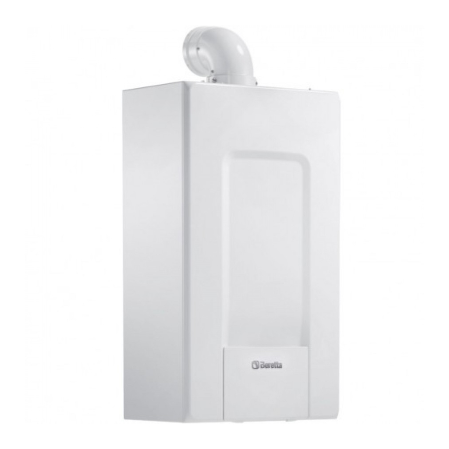
Summary of Contents for Beretta EXCLUSIVE R
- Page 1 Installer and user manual EXCLUSIVE R INSTALLER AND USER MANUAL MANUAL DE INSTALACIÓN Y USO MANUAL DE INSTALARE SI UTILIZARE...
- Page 2 EXCLUSIVE boiler complies with basic requirements of the Installer’s-user’s manual 3-28 following Directives: Boiler operating elements - Gas directive 2009/142/EC Electric diagrams - Efficiency directive: Article 7(2) and Annex III of directive 92/42/ Hydraulic circuit Circulator residual head - Electromagnetic compatibility directive 2014/30/EU - Low-voltage directive 2014/35/EU - Directive 2009/125/EC Ecodesign for energy-using appliances - Directive 2010/30/EU Indication by labelling of the consumption of energy by energy-related products - Delegated Regulation (EU) No. 811/2013 - Delegated Regulation (EU) No. 813/2013. In some parts of the booklet, some symbols are used: WARNING = for actions requiring special care and adequate preparation.
-
Page 3: Warnings And Safety
DESCRIPTION installation, adjustment and maintenance errors or to improper use. The EXCLUSIVE boilers have a new ACC (Activate Combustion Control) After removing the packaging, make sure the content is in good system. This new control system, developed by Beretta, ensures condition and complete. Otherwise, contact the dealer from whom functionality, efficiency and low emissions under any conditions. you purchased the appliance. The ACC system uses an ionisation sensor immersed in the burner flame,... -
Page 4: Installation Regulations
EXCLUSIVE Under the safety valve, install a water collecting funnel with the 4. Activate a heat request via the room thermostat or the remote control corresponding discharge in the event of leaks due to the overpressure panel, so that the 3-way valve goes into heating mode. 5. Activate a request for hot water as follows: operate on the storage tank of the heating system. The domestic hot water circuit does not need a thermostat for 30” per minute so that the three-way valve cycles from safety valve, but make sure that the pressure of waterworks does not heating to hot water and vice versa for about ten times (in this situation, exceed 6 bar. In case of doubts, install a pressure reducer. the boiler will go into alarm due to lack of gas, therefore reset it whenever Prior to ignition, make sure that the boiler is designed to operate this is proposed). with the gas available; this can be checked by the wording on the 6. Continue the sequence until no more air is felt coming from the air vent packaging and by the adhesive label indicating the gas type. -
Page 5: Gas Connection
ENGLISH It is obligatory to make the connection with a safe ground/earth, in “Straight length” means with terminals and joints but without bends. compliance with current directives. The boiler is supplied without the flue gas outlet/air suction kit, since it is possible to use the accessories for condensing appliances that To ensure the tightness of the boiler, use a self-locking cable tie and better adapt to the installation characteristics (see catalogue). tighten it on the fair lead used. The maximum lengths of the pipes refer to the flue accessories It is the responsibility of the installer to provide suitable grounding available in the catalogue. - Page 6 EXCLUSIVE Table of standard pipe configurations (*) Filling the heating system (fig. 16) Once the hydraulic connections have been carried out, fill the heating 1 bend 90° ø 80 Air suction system. This operation must be carried out when the system is cold,carrying 4,5m pipe ø 80 out the following operations: 1 bend 90° ø 80 - open the caps of the lower (A) automatic air vent valve by two or three 4,5m pipe ø 80 turns; to allow a continuous venting of the air, leave the plug of the valve Flue gas discharge Reduction from ø 80 to ø50, from ø 80 to ø 60...
- Page 7 ENGLISH 3.11.3 Alarm status indication If the button (A) is pressed you can move back to the “active settings display” again and check that the LEDs (B) and (C) indicate (for 2 seconds) the last If the circulator has detected one or more alarms the two-coloured LED (B) setting carried out. will be red. The four yellow LEDs (C) indicate the type of alarm as shown If the button (A) is not pressed for more than 2 seconds the user interfaces in the following table. switches to the “Operating status display”. ALARM Status Possible The available settings are shown in figure along with the related representation LED status description CIRCULATOR SOLUTION of LED (B) and (C). Red LED on + Start attempt The drive shaft Wait or unjam LED 1 LED 2 LED 3 LED 4 LED 5 1 yellow LED every 1.5 is jammed the drive shaft...
-
Page 8: Control Panel (Rec10)
EXCLUSIVE CONTROL PANEL (REC10) The REC10 remote control has the function of machine interface, displaying the system and providing access to the parameters. The middle of the main screen displays the delivery storage tank temperature (in case of storage tank with probe - optional), unless a heat request is in progress, in this case the delivery temperature of the boiler at that particular time is displayed. The value expressed in bar refers to the system’s water pressure. The top of the screen shows the information regarding the current date PLANT 18/05/2013 12:17... - Page 9 ENGLISH DEFAULT VALUE MINIMUM MAXIMUM ACCESS LEVEL MENU FACTORY SET VALUE VALUE NOTES VALUE SETTINGS USER TIME & DATE USER LANGUAGE ITALIANO / ENGLISH USER BACKLIGHT 5 min 1 min 15 min USER TIME SCHEDULE USER USER MAIN Only if POR = 1 USER ZONE1 Only if POR = 1...
- Page 10 EXCLUSIVE MINIMUM MAXIMUM ACCESS LEVEL DEFAULT VALUE FACTORY SET VALUE VALUE NOTES VALUE PARAMETERS INSTALLER TIMER OFF CH 3 min 0 min 20 min INSTALLER HYST ON HIGH TEMP 5°C 2°C 10°C SERVICE HYST OFF HIGH TEMP 5°C 2°C 10°C SERVICE HYST ON LOW TEMP 3°C...
- Page 11 ENGLISH DEFAULT VALUE MINIMUM MAXIMUM ACCESS LEVEL FACTORY SET VALUE VALUE NOTES VALUE SWEEPER INSTALLER ACTIVATE FUNCTION INSTALLER DEACTIVATE FUNCTION INSTALLER MAX SPEED INSTALLER RANGE RATED SPEED RANGE RATED INSTALLER MIN SPEED INSTALLER CHANGE FAN SPEED Current speed INSTALLER F. NOT ACTIVE / DAILY FUNCTION / ANTI-LEGIONELLA WEEKLY FUNCTION INSTALLER...
- Page 12 EXCLUSIVE DEFAULT VALUE MINIMUM MAXIMUM ACCESS LEVEL FACTORY SET VALUE VALUE NOTES VALUE INSTALLER ADD HEAT PUMP Only if heat pump not configured HEAT PUMP INSTALLER INSTALLER REMOVE HEAT PUMP Only if heat pump configured USE FREE CONTACTS / USE BUS USE BUS USE BUS USE FREE CONTACTS...
-
Page 13: Preliminary Checks
ENGLISH COMMISSIONING Access to the technical parameters Through the REC10 it is possible to access, using the TECHNICAL menu, Preliminary checks a series of parameters that can be programmed to allow you to personalise the operation of the boiler: First ignition is carried out by competent personnel from an authorised Technical Assistance Service Beretta. - select MENU on the initial page of the REC10 and press the key Before starting up the boiler, check: - that the data of the supply networks (electricity, water, gas) correspond PLANT to the label data 18/05/2013 12:17 - that the extraction pipes of the flue gases and the air suction pipes are 1.3 bar... -
Page 14: Boiler Configuration
EXCLUSIVE PARAMETERS PLANT 18/05/2013 12:17 1.3 bar MENU STATE TIMER OFF CH RESET TIMERS CH °C DHW THERMOSTAT INFO INSTALLER HOT WATER TEMPERATURE - TIMER OFF CH This parameter allows you to change the TIMER OFF CH, regarding the delay time introduced for re-igniting the burner in the face of an off STATE due to the heating temperature being reached. The factory setting for this parameter is 3 minutes and can be set to a value between 0 min and 20 min selecting the desired one with the “up”... - Page 15 ENGLISH 5.2.2 Configuration of the zone - TYPE OF ZONE This parameter allows you to specify the type of zone to be heated, it It is possible to customise the management of the heating zone by is possible to choose from among the following options: accessing the ZONES MANAGER menu. HIGH TEMPERATURE (factory setting): - Access the technical parameters as explained in the section “4.1 Access LOW TEMPERATURE to the technical parameters” . - MIN SET HEAT - In sequence select INSTALLATION, ZONES MANAGER and MODIFY This parameter allows you to specify the minimum heating setpoint that...
- Page 16 EXCLUSIVE MAIN ANTI-LEGIONELLA START 07:30 08:30 SELECT FUNCTION NOT ACTIVE A DAY 11:30 13:30 18:00 22:30 THURSDAY DAILY FUNCTION WEEKLY FUNCTION ZONE SCHEDULE INSTALLER 5.2.5 Setting the thermoregulation 5.2.4 Time band schedule function (room thermostat) Thermoregulation only works with the outdoor temperature sensor connected and active only for the HEATING function; therefore, once It is possible to set a time schedule for heating function and for the storage installed, connect the outdoor temperature sensor to the specific...
- Page 17 ENGLISH SELECTING THE COMPENSATION CURVE- fig. 17 The compensation curve for heating maintains a theoretical temperature of 20°C indoors, when the outdoor temperature is between +20°C and -20°C. STATE The choice of the curve depends on the minimum outdoor temperature envisaged (and therefore on the geographical location), and on the delivery temperature envisaged (and therefore on the type of system). It is carefully calculated by the installer on the basis of the following formula: BOILER KT = T. outlet envisaged - Tshift 20- min. design external T Tshift = 30°C standard system MAIN ZONE 25°C floor installations...
-
Page 18: Disable Function
EXCLUSIVE - select STOP FUNCTION with the “up” and “down” keys, confirming the selection VENT CYCLE HEATING DISABLE FUNCTION HOT WATER ENABLE FUNCTION STOP FUNCTION INSTALLER Adjusting the heating water temperature with an outdoor temperature sensor connected The REC10 will briefly display a wait message after which you will When an outdoor temperature sensor is installed, the outlet temperature automatically be taken to the main screen. - Page 19 ENGLISH Boiler start-up TECHNICAL If there is a room thermostat or a programming timer, or the REC10 MASTER is set as an ambient regulator, it is necessary that these are on RANGE RATED and that they have been adjusted to a temperature higher than the ambient CALIBRATION temperature so that the boiler switches on. The boiler will be in standby until the burner switches on following a heat SWEEPER request. The display shows “ ” to indicate the presence of a flame. EXHAUST PROBE RESET PLANT 18/05/2013 12:17 SCREED HEATING 1.3 bar MENU STATE INSTALLER - select ACTIVATE FUNCTION with the “up”...
-
Page 20: Combustion Check
EXCLUSIVE 5.13 Combustion check BOILER To carry out the combustion analysis, proceed as follows: - power the boiler electrically by setting the main system switch to “ON” - set the status of the boiler to OFF - access the technical parameters as explained in the section “4.1 Access to the technical parameters” SUMMER - select SWEEPER with the “up” and “down” keys, confirming the selection WINTER TECHNICAL PARAMETERS THERMOREGULATION 5.12 Gas conversion RANGE RATED It is easy to convert from one gas family to another even after the boiler CALIBRATION has been installed. This operation must be performed by professionally qualified staff. - Page 21 ENGLISH EXCLUSIVE 25R Curva portata termica - giri ventilatore Caldaia Vision+ 24C PLUS HTG curve (Qnheating) 8400 8000 7600 7200 6800 6400 6000 5600 5200 4800 4400 4000 3600 3200 2800 2400 When the checks are completed: 2000 - set the boiler to “SUMMER” (only if connect a storage tank) or “WINTER” 1600 mode depending on the season 1200 - regulate the heat request temperature values according to the customer’s Portata termica (kW)
- Page 22 EXCLUSIVE 5.15 Lights and faults For fault E091 The boiler has an auto-diagnostic system which, based on the total number If any faults should occur, a screen will appear on the display indicating of hours in certain operating conditions, can signal the need to clean the the relative error code and a brief alphanumeric description of the same. primary exchanger (alarm code E091). Once the cleaning operation has Pressing the “back” button it is possible to return to the main screen, been completed, reset to zero the total hour meter with special kit supplied where a fault is signalled by this flashing icon as an accessory following procedure indicated below:...
- Page 23 ENGLISH Boiler faults list ERROR DESCRIPTION OF TYPE ERROR MESSAGE RED LED GREEN LED RED and GREEN CODE OF ALARM E010 flame lockout/ACF electronic fault definitive flashing E011 extraneous flame transitional 0.2 sec. on/0.2 off flashing E020 limit thermostat definitive 0.5 sec. on/0.5 off E030 fan fault definitive E040 water transducer – load the system definitive flashing E041...
- Page 24 EXCLUSIVE 5.16 Alarm history The ALARM HISTORY function is automatically enabled only after the STORAGE TANK machine has been powered up for at least 2 consecutive hours, during this period of time any alarms that arise would not be saved in the “alarm history”. REMOVE STORAGE TANK The alarms can be displayed in chronological order, from the most recent to the oldest, up to a maximum of 5 alarms; to display the alarm history: STORAGE TANK TYPE - access the technical parameters as explained in the section “4.1 Access to the technical parameters”...
- Page 25 ENGLISH 5.21 System configuration This operation must be carried out only by professionally qualified personnel. When restarting after a replacement of the REC10 rather than after a “SYSTEM RESET”, the remote control displays an initial screen with the firmware revision. Pressing “ok” a guided procedure is started for configuring the system; select the desired options with the “up”...
-
Page 26: Boiler Type
EXCLUSIVE Whenever a “NEW” configuration is selected, proceed as follows: - select REC10 functionality: ON BOARD: if the REC10 is used only as a system interface and not as an ambient regulator AMBIENT: if the REC10 is used as a system interface and also as an SELECT THE TYPE ambient regulator of the zone where it is installed OF CONFIGURATION FROM AKM BOILER WHERE IS THE REC10 INSTALLED? ON BOARD AMBIENT 5.23 Replacing the AKM01 board The configuration operations should be carried out by professionally qualified personnel of the Technical Assistance Centre. -
Page 27: Maintenance
ENGLISH - Select BOILER TYPE Note: in case of replacement of the electrode, slight variations of the - Set this parameter depending on the type of boiler as shown in the table combustion parameters can not be excluded. These data wil return to nominal values after a few hours of operation. BOILER TYPE Do not clean the appliance or its parts with inflammable substances (e.g. petrol, alcohol, etc.). Do not clean panels, painted parts and plastic parts with paint thinner. Panel cleaning must be carried out only with soapy water. Maintenance of the combustion control system Maintenance electrode The detection electrode/ionization sensor has an important function in the SERVICE boiler ignition phase and in the maintenance of a proper combustion; in this context, in case of replacement, it is necessary to always ensure that BOILER TYPE it is correctly positioned and to strictly observe the reference shown in the... -
Page 28: User Guide
EXCLUSIVE USER GUIDE Depending on the type of application, some of the functions described in this manual might not be available. CONTROL PANEL REC10 The REC10 remote control unit has the function of a machine interface, as it displays the system’s settings and allows the parameters to be accessed. -
Page 29: Start Screen
ENGLISH START SCREEN Boiler This function can be selected in order to set the boiler’s status, by choosing Upon ignition, the REC10 might: one of the following options: - request the setting of the time and date (see paragraph “12.1.1 Time - OFF and date” ). - SUMMER - display the firmware version and require a button to be pressed in order - WINTER. to continue. The highlighted status is that which is currently selected. In order to select a different status highlight it using the “up” and “down” keys and then press By pressing the “up”... - Page 30 EXCLUSIVE 10.2 Domestic hot water (only when storage tank with 9.2.1 probe is connected) If ON is selected, the zone requests are met. Press the “up” and “down” keys to change the boiler’s domestic hot water 9.2.2 AUTO setpoint. Press “ok” to confirm the selection. If AUTO is selected, the zone requests will be managed based on a Press “back” to return to the screen without making any selection. scheduled programme.
-
Page 31: Time Schedule
ENGLISH A message for the system efficiency level can be displayed in the top of the screen: MENU - HIGH EFFICIENCY (if the average value of the return probe > 55°C) - OPTIMUM EFFICIENCY (if 25°C < average value of the return probe < SETTINGS 55°C) : 30 days TIME SCHEDULE 05:11 SELECT OPTION 12.1 Settings Select this function to modify the following settings: - TIME AND DATE - LANGUAGE - BACKLIGHT. OPTIMUM EFFICIENCY To access the desired setting, it is necessary to highlight it using the “up”... - Page 32 EXCLUSIVE 13.1 Add Press the “up” and “down” keys to select the desired time band and press “ok” to confirm the selection. This function serves to add a new time frame to the selected day. Press “ok” to select the function, after having highlighted it (if necessary) MAIN using the “up” and “down” keys. START THURSDAY MAIN 07:30 08:30 SELECT 11:30 13:30 PERIOD TO START 18:00 22:30 THURSDAY MODIFY 07:30 08:30 11:30 13:30 18:00 22:30 07:30 MODIFY DELETE COPY USE THE ARROWS TO MODIFY Press the “up”...
- Page 33 ENGLISH Press the “up” and “down” keys to select the desired time band and press In order to confirm that the operation has been completed successfully, the “ok” to confirm the selection. display will show the list of days to which the scheduled programme has been copied. MAIN MAIN START THURSDAY 07:30 08:30 SELECT 11:30 13:30 PERIOD TO SCHEDULE OF THURSDAY 18:00 22:30 DELETE WILL BE COPIED ON THE DAYS : TUESDAY USE THE ARROWS TO MODIFY USE THE ARROWS TO MODIFY To confirm or cancel the selection made, highlight the corresponding option and confirm it by pressing “ok”.
- Page 34 EXCLUSIVE Boiler faults list ERROR DESCRIPTION OF TYPE ERROR MESSAGE RED LED GREEN LED RED and GREEN CODE OF ALARM E010 flame lockout/ACF electronic fault definitive flashing E011 extraneous flame transitional 0.2 sec. on/0.2 off flashing E020 limit thermostat definitive 0.5 sec. on/0.5 off E030 fan fault definitive E040 water transducer – load the system definitive flashing E041...
-
Page 35: Reset Function
ENGLISH Warning lights BOILER STATUS RED LED GREEN LED RED and GREEN NOTES flashing Power-on The red and green LEDs come on at the same time 0.5 sec. on/0.5 sec. off flashing flashing Vent cycle The red and green LEDs come sequentially one at a time 0.5 sec. on/1 sec. off 0.5 sec. on/1 sec. off flashing OFF status 0.3 sec. on/0.5 sec. off flashing No heat request (stby) 0.3 sec. on/0.5 sec. off Transitional ignition/ flashing overtemperature 0.3 sec. on/0.5 sec. off... -
Page 36: Technical Data
EXCLUSIVE TECHNICAL DATA EXCLUSIVE DESCRIPTION Heating Rated heat input 18,00 30,00 kcal/h 15.480 25.800 Nominal heat output (80°/60°) 17,60 29,37 kcal/h 15.139 25.258 Nominal heat output (50°/30°) 19,17 31,77 kcal/h 16.486 27.322 Reduced heat input 3,70 5,20 4,90 6,90 kcal/h 3.182 4.472 4.214 5.934 Reduced heat output (80°/60°) 3,61 5,03 4,74 6,76... - Page 37 ENGLISH EXCLUSIVE DESCRIPTION Heating output Air capacity 21,496 21,926 36,447 37,228 Flue gas capacity 23,302 23,322 39,456 39,555 8,044- 8,221- 13,629- 13,946- Mass flue gas flow rate (max-min) 1,671 2,375 2,205 3,207 Domestic hot water capacity Air capacity 31,050 31,671 Flue gas capacity 33,658 33,688 11,619- 11,874- Mass flue gas flow rate (max-min) 1,671 2,375 Fan performance Residual discharge head of concentric pipes 0.85 m Residual discharge head of separate pipes 0.5 m Residual discharge head of boiler without pipes...
- Page 38 EXCLUSIVE EXCLUSIVE PARAMETERS METHANE GAS (G20) LPG (G31) Lower Wobbe index (at 15°C-1013 mbar) MJ/m³S 45,67 70,69 Net Calorific Value MJ/m³S 34,02 Supply nominal pressure mbar (mm H2O) 20 (203,9) 37 (377,3) Minimum supply pressure mbar (mm H2O) 10 (102,0) Burner: diameter/length 63/110 63/110 Number of diaphragm holes n° Diaphragm holes diameter Sm³/h 1,90 Heating maximum gas capacity kg/h 1,40 Sm³/h 2,75 DHW maximum gas capacity kg/h 2,02 Sm³/h 0,39...
-
Page 39: Functional Elements Of The Appliance
EXCLUSIVE 25kW 35kW Functional elements of the appliance Conveyor 18 NTC delivery probe 10 Fan 19 Flame ignition electrode Pressure gauge 11 Mixer 20 Flame detection electrode/Ionization sensor Drain valve 12 Ignition transformer 21 Expansion vessel 3 3-way valve stepper servomotor 13 Flue gas exhaust 22 Main heat exchanger Safety valve 14 Degassing unit pipe 23 Pressure transducer 5 Circulator 15 Flue gas probe... - Page 40 EXCLUSIVE “L-N” POLARITY IS RECOMMENDED...
-
Page 41: Water Circuit
EXCLUSIVE Multiwire wiring diagram Room thermostat (contact must be free of voltage) TBOL Water tank thermostat Blu=Blue/Marrone=Brown/Nero=Black/Rosso=Red/Bianco=White/ Low temperature limit thermostat Viola=Violet/Rosa=Pink/Arancione=Orange/Grigio=Grey/Giallo=Yellow/ Outdoor temperature sensor Verde=Green OT+ Open therm A = Gas valve SBOL Water tank probe B = 230V auxiliary X1 - X2 Not used C = Not used Pump D = Voltage free contact input PWM signal pump modulation AKM0X Control board Gas valve operator Remote control panel V Hv Fan power supply 230 V BE20 Board led: TSC2 Ignition transformer green led (operating or temporary stop) - Page 42 EXCLUSIVE Residual head of circulator Bear in mind that the boiler will operate correctly To this end, the boiler is fitted with an automatic The residual head for the heating system is if there is sufficient water circulation in the heat by-pass which is designed to ensure water flow represented in graphic 1, according to the flow exchanger.
- Page 43 EXCLUSIVE A = condensate drain B = water - gas Indoor installation Outdoor installation in a partially protected place measured in mm distances in mm...
- Page 44 EXCLUSIVE boiler support plate (F) 1 2 3 4 5 6 7 8 9 10 11 12 13 14 15 16 17 18 19 20 - A B + OT+ SBOL X1 TA TBOL TBT SE Voltage free contact input 1-2-3-4 (- A B +) Bus 485 Room thermostat (contact without voltage) TBOL Water tank thermostat 9-10...
- Page 45 EXCLUSIVE FLUE GASES SUCTION PIPES IN SITES COAXIAL PIPE Ø 60-100mm 90° bend adaptor flange installed as standard flange installed as standard TWIN PIPE Ø 80mm COAXIAL PIPE Ø 80-125mm 90° bend 90° bend flange installed flange installed as standard as standard TWIN PIPE KIT (from Ø60-100mm to Ø80-80mm)
- Page 46 EXCLUSIVE chimney for ducting Ø 50 mm or Ø 60 mm or Ø 80 mm 90° bends Ø 80 mm 4,5m Ø 80 mm 4,5m Ø 80 mm 90° bend Ø 50 mm Ø 60 mm or Ø 80 mm Ø 80-60 mm or Ø 80-50 mm reduction CURVE DI TERMOREGOLAZIONE 25 ° C 20 °C 15 °C Temperatura esterna (˚C) Riduzione notturna P ARALLELA A GRAPHIC 1 - THERMOREGULATION CURVES B GRAPHIC 2 - WEATHER COMPENSATION CURVE Curva climatica GIORNO C GRAPHIC 3 - PARALLEL NIGHT-TIME REDUCTION D OUTSIDE TEMPERATURE (°C)
- Page 47 MAX LENGTH PIPES Ø 80 + Ø 80 Caldaia Exclusive 25C n lunghezza massima tubi ø 80 mm EXCLUSIVE 25R 95 100 105 110 115 120 125 130 135 140 145 150 155 160 165 170 175 Lunghezza tubo aspirazione aria (m) air suction pipe length (m) EXCLUSIVE 35R air suction pipe length (m)
- Page 48 Via Risorgimento, 23/A 23900 LECCO Italy info@berettaboilers.com www.berettaboilers.com In order to improve its products, Beretta reserves the right to modify the characteristics and information contained in this manual at any time and without prior notice. Consumers statutory rights are not affected.
Need help?
Do you have a question about the EXCLUSIVE R and is the answer not in the manual?
Questions and answers