Table of Contents
Advertisement
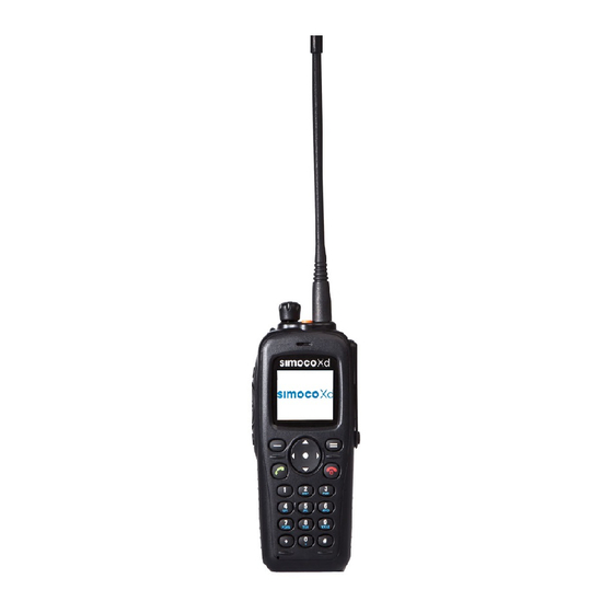
SDP660 PORTABLE RADIO
Field House,
Uttoxeter Old Road
Derby
DE1 1NH
Tel:
+44 (0) 1332 375500
FAX:
+44 (0) 1332 375501
http://www.simocogroup.com
USER MANUAL
TNM-U-E-0114, Issue 1.1B
July 2013
©Simoco 2013
1270 Ferntree Gully Road,
Scoresby
Victoria, 3179
Australia
Tel:
+61 (0)3 9730 3999
FAX:
+61 (0)3 9730 3988
http://www.simocogroup.com
Advertisement
Table of Contents

Related Manuals for Simoco SDP660


Summary of Contents for Simoco SDP660
-
Page 1: Title Page
SDP660 PORTABLE RADIO USER MANUAL TNM-U-E-0114, Issue 1.1B July 2013 Field House, 1270 Ferntree Gully Road, Uttoxeter Old Road Scoresby Derby Victoria, 3179 DE1 1NH Australia Tel: +44 (0) 1332 375500 Tel: +61 (0)3 9730 3999 FAX: +44 (0) 1332 375501... -
Page 2: Preface
OPYRIGHT All information contained in this document is the property of Simoco. All rights are reserved. This document may not, in whole or in part, be copied, photocopied, reproduced, translated, stored, or reduced to any electronic medium or machine-readable form, without prior written permission from Simoco. - Page 3 TNM-U-E-0118. PAR-600CRG1 Single Rapid Charger – SDP650/660 Instruction Manual, Issue 1.0, dated January 2013. To order printed copies of this or any of the above publications, please contact Simoco. See the Support page for contact information. A comprehensive list of documentation is available for download on the Simoco website http://www.simocogroup.com...
-
Page 4: Table Of Contents
SDP660 – USER MANUAL TNM-U-E-0114 TABLE OF CONTENTS Page Title Page ............................1 Preface ............................2 Table of Contents (This List) ....................... 4 List of Figures ..........................6 List of Tables ..........................7 Personal Safety ..........................8 Warnings ............................8 Compliance with RF Energy Exposure Guidelines (United States and Canada) .... - Page 5 SDP660 – USER MANUAL TNM-U-E-0114 ........................ 30 AKING A ......................31 ECEIVING A ....................... 32 OTING UNCTIONS 5.9.1 Scan/ Voting Screen....................32 5.10 E ......................33 MERGENCY LARM 5.10.1 Making an Emergency Call..................33 MENU SYSTEM........................34 ......................35 AVIGATION MENU SCREENS ........................
-
Page 6: List Of Figures
Figure 2. Fitting the Antenna......................20 Figure 3. Fitting the Belt Clip......................21 Figure 4. Fitting Audio Accessory/Programming Cable..............21 Figure 5. SDP660 Controls......................22 Figure 6. Default Screen Layout....................24 Figure 7. Initial Screen......................... 28 Figure 8. -
Page 7: List Of Tables
Table 1. Charge Indications......................20 Table 2. SDP660 – Controls......................23 Table 3. LED Indications......................23 Table 4. Icon Details........................25 Table 5. SDP650 and SDP660 DMR Portable Radio Accessories..........56 Table A1. Alert Tones........................58 Jul 13 (Iss 1.1) Page 7... -
Page 8: Personal Safety
SDP660 – USER MANUAL TNM-U-E-0114 PERSONAL SAFETY AFETY RECAUTIONS These Safety Precautions, Warnings and Cautions advise personnel of specific hazards which may be encountered when using the equipment covered in this manual and that control measures are required to prevent injury to personnel, and damage to equipment and/or the environment. -
Page 9: Hints For Using The Radio
SDP660 – USER MANUAL TNM-U-E-0114 Radio Frequency Radiation WARNING RADIO FREQUENCY RADIATION. A RADIO FREQUENCY (RF) RADIATION HAZARD EXISTS IN THIS EQUIPMENT. TO AVOID RF INJURY, DO NOT TOUCH THE ANTENNA WHEN THE TRANSMITTER IS IN USE. DO NOT OPERATE TRANSMITTER WITH THE ANTENNA DISCONNECTED. -
Page 10: Compliance With Rf Energy Exposure Guidelines (United States And Canada)
RF exposure and to satisfy compliance regulations. Compliance with RF Exposure Standards Simoco two-way radios are designed and tested to comply with a number of national and international standards and guidelines (listed below) for human exposure to RF electromagnetic energy. - Page 11 Guidelines: User awareness instructions should accompany the device when transferred to other users. • This radio meets the FCC RF exposure guidelines when used with the Simoco accessories • supplied or designated for the product. The designated Simoco belt clip type is PAR- 600CLIP and the extension speaker microphone types are PAR-9180LMS2-2, PAR- 9180LMW1 and PAR-600LMS4.
- Page 12 SDP660 – USER MANUAL TNM-U-E-0114 Approved Accessories This radio meets the FCC RF exposure guidelines when used with the Simoco accessories • supplied or designated for the product. Use of other accessories may not ensure compliance with the FCCs RF exposure guidelines and may violate FCC regulations.
-
Page 13: General Notes
GENERAL NOTES ANUAL OMPILATION This manual provides detailed information on the use of the SDP660 DMR Portable Radio Transceiver including Getting Started, Front Panel Controls, Main Screen, Basic Operations, Menu System, Menu Screens, Special Functions and Accessories. Details of both the “default” and “optional” system configurations have been included in this User Manual, therefore, some material may not be relevant to every system. -
Page 14: Support - Contact Information
SDP660 – USER MANUAL TNM-U-E-0114 SIMOCO SUPPORT ONTACT NFORMATION At Simoco we welcome your comments, feedback and suggestions. Departmental contacts have been provided for your quick reference below. UK Customer Services Email: customer.service@simocogroup.com Tel: 08717 411 050 International: +44 (0) 1332 375 671... -
Page 15: Abbreviations
SDP660 – USER MANUAL TNM-U-E-0114 ABBREVIATIONS The following abbreviations are used through out this document. Whenever practicable, wherever the abbreviation is first used the full meaning is given with the abbreviation in parenthesis, after that only the abbreviation will be used. -
Page 16: Glossary
SDP660 – USER MANUAL TNM-U-E-0114 GLOSSARY OF TERMS The table below contains a list of the common terms used through out this document and their meanings. Term Meaning ‘……’ Reference to a setting or feature (exactly as it is displayed) that may be selected or enabled either directly or through a software application, e.g. -
Page 17: Introduction
SDP660 Series Radios. ONFIGURATION Before the SDP660 radio can be used it must be configured using the Field Personality Programmer (FPP). The configuration process loads the customised channels, signalling and user options so that the radio will operate with the user’s system. - Page 18 SDP660 – USER MANUAL TNM-U-E-0114 Full colour display with intuitive interface. • Jul 13 (Iss 1.1) Page 18 INTRODUCTION...
-
Page 19: Getting Started
TNM-U-E-0114 GETTING STARTED This User Manual covers the basic operation of the Simoco SDP660 Digital Portable radio. The radio is software programmable and can be customised to the operational requirements of a customer’s specific needs. Simoco representatives can help in programming the radio facilities to meet a customer’s present and future requirements. -
Page 20: Fitting The Battery
SDP660 – USER MANUAL TNM-U-E-0114 Table 2. Charge Indications. LED States Charge State Red LED Green LED Battery absent Fast Charge Charge Complete Charge suspended (High or Low Temp 1 Hz Flashing 2.1.2 Fitting the Battery Insert the battery into the bottom of the radio. (See arrow 1 in Figure 1 below). -
Page 21: Fitting The Belt Clip
Figure 4. Fitting Audio Accessory/Programming Cable. ONFIGURATION Before the SDP660 radio can be used it must be configured using the Field Personality Programmer (FPP). The configuration process loads the customised channels, signalling and user options so that the radio will operate with the user’s system. -
Page 22: Front Panel Controls
Multi-coloured LED for a clear indication of radio status. • Full colour display with intuitive interface. • The Controls of the SDP660 Portable radio are shown below in Figures 5. Right Left Select Down Figure 5. - Page 23 SDP660 – USER MANUAL TNM-U-E-0114 The functions of each of the controls are detailed below in Table 3. Table 3. SDP660 – Controls. Control Label Function Multi coloured LED. See Table 4 below for full details of colour Tx/Rx/Power LED indications.
-
Page 24: Main Screen
SDP660 – USER MANUAL TNM-U-E-0114 MAIN SCREEN EFAULT CREEN AYOUT The default screen layout is shown below in Figure 6. Battery Tx/Rx Icon Level Icon 1 …………………… Icon 6 Icon Bar Soft Labels Figure 6. Default Screen Layout. The screen has three main areas: the Icon Bar; the Text Panel; and the Soft Labels area. - Page 25 SDP660 – USER MANUAL TNM-U-E-0114 Battery Icon. This is always displayed on the default screen at the top left on the Icon bar. • Ii indicates the condition of the battery. Rx Signal Strength. This is displayed on the default screen at the top right on the Icon bar.
- Page 26 SDP660 – USER MANUAL TNM-U-E-0114 Icon ICON INDICATION Position Emergency Call. Individual Emergency. Priority Group Call. Icon 4 Priority Individual Call. (Call Type contd.) All Call. Broadcast Call. OVCM Group Call. OVCM Individual Call. Data Call. Icon 5 Talk Around enabled. Talk Around is enabled for current channel only.
- Page 27 SDP660 – USER MANUAL TNM-U-E-0114 Jul 13 (Iss 1.1) Page 27 MAIN SCREEN LAYOUT...
-
Page 28: Basic Operations
To turn the radio On, press the Red handset button (F12), the initial opening screen will be displayed. When the radio is switched on and power is applied, the radio displays ‘Simoco Xd’ while the DSP boots up the radio. -
Page 29: Welcome Screen
SDP660 – USER MANUAL TNM-U-E-0114 ELCOME CREEN Within the FPP there is a ‘Welcome Text’ field, which enables a welcome message to be displayed on the screen when the radio is switched on. If the Welcome Text has been defined, the radio will display the welcome message and radio ID for two seconds while the radio initialises. -
Page 30: Adjusting The Volume
SDP660 – USER MANUAL TNM-U-E-0114 The FPP has a ‘Lock/Unlock’ enable function that can be assigned to a function button. If this has been assigned, pressing the relevant function button will unlock the keypad. The FPP also has an ‘Auto-Lock Keys’ option. When this is enabled, the keypad will locked automatically if there are no valid key press within the preset time period (normally 10 s). -
Page 31: Receiving A Call
SDP660 – USER MANUAL TNM-U-E-0114 In most systems, it is good practice to wait a short time (0.5 secs) between pressing the PTT switch and commencing to speak. This allows the transmission path to be properly established (or not) and avoids lost or distorted speech. -
Page 32: Can / Voting Functions
SDP660 – USER MANUAL TNM-U-E-0114 OTING UNCTIONS The Scan Function allows the sequential searching of up to 16 channels, if the selected zone channel is programmed as a Scan channel, for a valid signal (Carrier + CTCSS/DCS tone for Analogue FM or Colour Code for DMR). When found, the radio will stop on that channel until the signal disappears again. -
Page 33: Emergency Alarm
SDP660 – USER MANUAL TNM-U-E-0114 5.10 E MERGENCY LARM 5.10.1 Making an Emergency Call When the emergency key is pressed and held for a time determined by the FPP, the radio will change to emergency mode. Under emergency mode, the radio can operate in three FPP configurable modes: Frozen. -
Page 34: Menu System
MENU SYSTEM This section details the operation of the menu system for the SDP660 Portable Radios. The SDP660 radio software uses a programmed menu structure to enable the operator to access the radio options. The structure of the menu can be configured using the FPP to meet a customer’s specific needs. -
Page 35: Menu Navigation
SDP660 – USER MANUAL TNM-U-E-0114 AVIGATION Pressing the ‘Menu’ (F1) key selects Menu mode from the main Channel Screen. Once in menu mode, the ▼ and ▲ keys scroll through the menus. To exit Menu mode, press the ‘Back’ (F4) key or the Menu timeout will exit automatically. -
Page 36: Menu Screens
SDP660 – USER MANUAL TNM-U-E-0114 MENU SCREENS The menu structure on the SDP660 Portable Radio is configurable using the FPP. A system administrator usually tailors the order and presence of the menu options to specific customer requirements. This section describes all the menus that are currently available. -
Page 37: Zone Menu
SDP660 – USER MANUAL TNM-U-E-0114 The Zone menu is used for changing Zones. A Zone is normally defined as a group of radio channels with a common operational role. Zone Zone1 Zone2 Zone3 Zone4 Zone5 Select Back Figure 13. Zone Menu. -
Page 38: Options Menu
SDP660 – USER MANUAL TNM-U-E-0114 Radio Status; or • User Options. • PTIONS The Options menu allows the user access to a preset selection of menu options for user radio interface configuration items. These include the backlight timeout period, the backlight brightness, speaker and alert tone volume control limitations, and the key beeps function. -
Page 39: Information Menu
SDP660 – USER MANUAL TNM-U-E-0114 Pressing the PTT key will place a call to the selected contact. Details GRP 9003 9003 Group Select Back Figure 17. Individual contact details. The details displayed for the contact are: #0 – The serial number of the contact list entry. -
Page 40: Messages Menu
SDP660 – USER MANUAL TNM-U-E-0114 ESSAGES A radio unit can receive and transmit predefined short messages and text messages with another radio unit on a DMR channel. The Messages menu allows the user to view a preset menu screen which allows the radio user to check the state of the various digital message systems in the radio. -
Page 41: Outbox
SDP660 – USER MANUAL TNM-U-E-0114 To return to the Messages Menu, press the ‘Back’ key. 7.7.2 Outbox The Outbox is used to store the transmitted (sent) messages. Up to 20 messages can be stored in the outbox. These messages are volatile, which means that, at radio start-up, the outbox will be empty. -
Page 42: Send Template
SDP660 – USER MANUAL TNM-U-E-0114 Press the ‘Back’ key to return to the previous screen. Press the ‘Select’ key to display the Send screen, which allows you to select a Contact from the Contacts menu. See Para 6.7.6 – Sending Status, Template and Text Messages for further information. -
Page 43: Sending Status, Template And Text Messages
SDP660 – USER MANUAL TNM-U-E-0114 Punctuation characters (full stop, comma, question mark, etc) are entered using the # key. A space is entered with the * key. Each line displays up to 12 characters. Up to five lines can be displayed at once. If more than five lines of text are entered, the lines will be scrolled up. -
Page 44: Mute Adjust Menu
SDP660 – USER MANUAL TNM-U-E-0114 Msg View SDM 202 test message Select Back Figure 27. Message View Screen. The information displayed for each message includes: either the name of the sender from the Contacts list or, if the ID is not known to the Contact list, the sender ID; and the first two lines of the messages in text string. -
Page 45: Backlight Menu
SDP660 – USER MANUAL TNM-U-E-0114 Mute Adjust Select Back Figure 29. Mute Adjust Menu. The default Mute Adjustment range is from 0 – 15. The mute adjustment setting will be applied to all the radio’s analogue channels. The SDP600 series radios have a carrier noise mute and it is recommended that a default mute setting of 4 is used. -
Page 46: Brightness Menu
SDP660 – USER MANUAL TNM-U-E-0114 The maximum backlight timeout period is programmed by the FPP. The numerical values on the display are in seconds. Note. Received radio traffic events will not prevent the backlight timeout. Use the ▼ and ▲ keys to select the required backlight timeout period. -
Page 47: Speaker Volume Menu
SDP660 – USER MANUAL TNM-U-E-0114 7.12 S PEAKER OLUME The Speaker Volume Menu allows the user to set the radio start-up value of the audio volume control for user comfort. The ‘Speaker Volume’ menu is located under the Options menu. -
Page 48: Adio Tatus Enu
SDP660 – USER MANUAL TNM-U-E-0114 7.14 R ADIO TATUS The Radio Status menu allows the User to view the condition of various parameters for the radio. These include RSSI, Battery Level, Accelerometer Orientation and the GPS co-ordinates. When accessed, the Radio Status menu will open on the RSSI screen. The other parameters can be viewed by using the ▼... -
Page 49: 7.14.3 Accelerometer Orientation
SDP660 – USER MANUAL TNM-U-E-0114 7.14.3 Accelerometer Orientation The Accelerometer Orientation is used during the Man Down mode. The Accelerometer Orientation screen displays the “raw” data from the accelerometer so its functionality can be checked. Accel Select Back Figure 37. Radio Status Menu – Accelerometer Orientation Screen. -
Page 50: Display Test
SDP660 – USER MANUAL TNM-U-E-0114 Scanning SCAN OFF SCAN ON Select Back Figure 40. Scan Menu. Use the ▼ and ▲ keys to select either the Scan On or Scan Off function. Press the ‘Select’ key initiate the action. 7.16 D... - Page 51 SDP660 – USER MANUAL TNM-U-E-0114 Jul 13 (Iss 1.1) Page 51 MENU SCREENS...
-
Page 52: Special Functions
TNM-U-E-0114 SPECIAL FUNCTIONS Special functions can be programmed to each of the keys/buttons on the SDP660 Portable Radio by the FPP. These special functions can be simple short cuts to specific menus or an on/off toggle facility for specific actions. -
Page 53: Reset
SDP660 – USER MANUAL TNM-U-E-0114 8.10 R ESET The Reset function is usually assigned to the F6 key, and is used as a cancel function when in a menu or as a backspace when entering keypad dial-strings. 8.11 S PEAKER The speaker mute function key will mute the audio output to the speaker. -
Page 54: Lone Worker
SDP660 – USER MANUAL TNM-U-E-0114 8.13 L ORKER Lone Worker is used to initiate emergency alarm mode when the user is unresponsive after a predetermined time. A data message is also sent to the device management software (via the gateway) indicating that the worker may be incapacitated. -
Page 55: Dial Strings
The dial plan specifies the sequence of key-presses which may be entered by the user via the SDP660 to initiate connectivity to a remote party using another terminal in the network. Additionally, dial strings may be entered to alter a terminal’s behaviour or configuration without initiating a call. -
Page 56: 10 Accessories
SDP660 – USER MANUAL TNM-U-E-0114 10 ACCESSORIES The accessories that are available for the SDP660 Portable Radio are listed below in Table 6. Contact Simoco for further information. Table 6. SDP660 DMR Portable Radio Accessories. Part No. Description Notes PAR-600BATL2... - Page 57 SDP660 – USER MANUAL TNM-U-E-0114 Part No. Description Notes Universal Serial Bus (USB) programming PAR-9180PRLDU SDP Programming Lead USB lead for use with the FPP when configuring the radio. SA-600IMD Intelligent Man-Down License SA-600MST* Multi-Site Trunking License * Available Q2 2013 Jul 13 (Iss 1.1)
-
Page 58: Alert Tones And Messages
SDP660 – USER MANUAL TNM-U-E-0114 APPENDIX A ALERT TONES AND MESSAGES LERT ONES The Alert Tones supported by the SDP600 Series Portable Radio are listed below in Table A1. Table A1. Alert Tones. Frequency, Tone Duration, Tone Description Repeats Key Beep 940 Hz 60 ms Generated by key presses. - Page 59 SIMOCO GROUP Global Headquarters: Field House, Uttoxeter Old Road, Derby DE1 1NH Tel: 08717 411 050 Fax: 08717 411 049 International: Tel: +44 (0) 1332 375 671 Fax: +44 (0) 1332 375 672 www.simocogroup.com...
Need help?
Do you have a question about the SDP660 and is the answer not in the manual?
Questions and answers