Table of Contents
Advertisement
Quick Links
Advertisement
Table of Contents

Subscribe to Our Youtube Channel
Related Manuals for Simoco P25


Summary of Contents for Simoco P25
- Page 1 SRP9180 / SRP9170 P25 Portable Radio P25 User Manual TNM-U-E-0091 V1.4b May 2011...
- Page 2 TNM-U-E-0102 SRP9180 Brief User Guide (General) To order copies of any of the above publications, or any other Simoco product, contact Comgroup Australia on +61 3 9730 3800 or send a Fax on +61 3 9730 3968. The Simoco web site also has a comprehensive list of documentation available for download.
- Page 3 • Servicing and upgrades of IECEx approved Intrinsically Safe radios and accessories must only be carried out by Simoco IECEx Intrinsically Safe trained staff, at locations that have been IECEx approved. Please contact the Simoco Help Desk on 1300 363 607 for your nearest approved Service Department.
- Page 4 SRP9170/80 P25 Portable Radio – User Manual Hints for Using the Radio When transmitting, hold the radio a few centimetres from your mouth and speak across it, rather than into it. The microphone is located near the bottom right hand corner of the portable radio’s speaker grille.
-
Page 5: Table Of Contents
SRP9170/80 P25 Portable Radio – User Manual CONTENTS INTRODUCTION ....................8 Overview......................8 Configuration ....................8 Modes of SRP9180 P25 Operation..............8 CONTROLS......................9 MENU SYSTEM....................11 Menu Navigation..................12 MENU SCREENS ....................14 Channel Screen ..................14 Menus ......................16 4.2.1 Zone ......................16 4.2.2 Squelch .....................18 4.2.3 Mute Adjust / Monitor (Analogue Channels)..........19 4.2.4... - Page 6 SRP9170/80 P25 Portable Radio – User Manual SPECIAL FUNCTION KEYS................52 Alarm......................52 Announce ....................52 Channel Up and Down ................52 Crypto ......................52 DTMF Send 1/2 (P25 Analogue) ...............52 Key Lock......................52 Low Power....................53 Menu ......................53 Mode ......................53 6.10 Mute......................53 6.11 Reset ......................53 6.12 Scan......................53...
- Page 7 SRP9170/80 P25 Portable Radio – User Manual 7.17 Programming Lead (MAR-9180PRLDU..........56 7.18 Belt Clip (PAR-9180CLIP)...............56 7.19 Stud Mount (PAR-9180STUD) ..............56 ALERT TONES AND MESSAGES ..............57 GLOSSARY......................58 COMPLIANCE WITH RF ENERGY EXPOSURE GUIDELINES (UNITED STATES AND CANADA) ...................60 © ComGroup Australia 2010 Page 7 TNM-U-E-0091 1.4a...
-
Page 8: Introduction
Generally, zones can be programmed with channels belonging to common function groups. A radio channel can be defined as either Analogue, a Conventional P25 Channel or a Trunked P25 talkgroup. A Zone may contain a mix of Channel types. -
Page 9: Controls
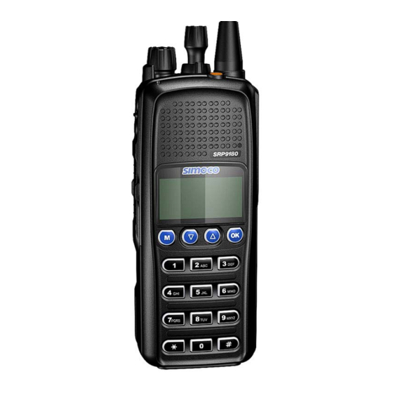
SRP9170/80 P25 Portable Radio – User Manual 2 CONTROLS Selector Switch Antenna ABC Switch Function #7 On/Off Volume Indicator LED Function #5 Function #6 Accessory Connector Function #3 Function #2 Function #4 Function #1 Keypad Figure 1 – SRP9180 Portable Key Layout... - Page 10 SRP9170/80 P25 Portable Radio – User Manual SRP9180 Label Function Key/Control 1 2 3 4 5 6 Keypad can be used to select a Channel or Special Keypad 7 8 9 Function. * 0 # E.g. 12# will select channel 12.
-
Page 11: Menu System
SRP9170/80 P25 Portable Radio – User Manual 3 MENU SYSTEM The SRP9180 P25 portable radio uses a menu structure for access to all of the radio features and functions. The structure of the menu can be programmed to meet the specific needs of individual customers. -
Page 12: Menu Navigation
SRP9170/80 P25 Portable Radio – User Manual AVIGATION Pressing the “M” key selects Menu mode from the main Channel Screen. Once in menu mode, the ▼ and ▲ keys cycle through the menus. To exit Menu mode, press the “M” key again or the Menu timeout will exit automatically. - Page 13 SRP9170/80 P25 Portable Radio – User Manual Note: Example Menus only shown. Back Back Squelch Submenu Other Menus may be configured with the FPP Back Mute Back Submenu OK Key Adjust Back Back Key Up Key Back Back RSSI Submenu...
-
Page 14: Menu Screens
If a radio channel is defined as a P25 Conventional Digital Channel, it will only receive P25 digital signals. If a radio channel is defined as an Analogue FM channel, it will receive both P25 Digital* and Analogue FM signals. - Page 15 Normal Mute. Only radio signals from the users own network will be heard on the speaker. Monitor. All P25 digital radio signals on the channel will be heard. All keys except PTT, or any function assigned as Alarm, will be disabled.
-
Page 16: Menus
SRP9170/80 P25 Portable Radio – User Manual Connecting icon. Shown when a text message is being sent and the connection is in progress. Connection Fail icon. Shown when a text message transmission has failed. Radio has stopped on a scan channel. - Page 17 SRP9170/80 P25 Portable Radio – User Manual Once the “Zone” menu appears, press the ▼ and ▲ keys to choose the required Zone. Press the “OK” key to select the required Zone. The radio will return to the channel screen and select the first channel in the new Zone.
-
Page 18: Squelch
Press the “OK” key for the “Squelch” Menu. P25 Squelch Screen For a P25 digital channel, pressing the ▼ and ▲ keys will allow selection of either Monitor, Normal or Selective squelch mode. For an analogue channel, pressing the ▼ and ▲ keys will allow selection of either Monitor or Normal squelch mode. -
Page 19: Mute Adjust / Monitor (Analogue Channels)
An “S” icon indicates Selective squelch. 4.2.2.2 Analogue Operation Channel Monitor Mode: The radio will receive any Analogue voice or P25 digital signals. Digital NAC or Analogue CTCSS is not checked. An “M” icon indicates monitor. Analogue Channel Normal Mode: When Normal mute is selected, the radio will receive correctly addressed Analogue radio transmissions and all decryptable or clear digital transmissions. -
Page 20: Phonebook
Phone book entries may be Individual Addresses, Telephone numbers or Talk Groups. The second line shows the name of the selected phone book entry. The third line shows the unit identifier of the phone book entry. This is the P25 ID that the radio will call. - Page 21 SRP9170/80 P25 Portable Radio – User Manual 4.2.4.1 Making an Individual Call In Phonebook mode, when the “PTT” key is pressed: The radio is changed to individual call mode (individual call to the unit identifier of the selected phone entry). The individual call icon is displayed.
-
Page 22: Phonebook Edit
SRP9170/80 P25 Portable Radio – User Manual 4.2.5 Phonebook Edit The Phone Book can be modified so that new entries can be added and existing entries can be modified or removed from the phone book. Phone book entries may be Individual Addresses, Telephone numbers or Talk Groups. - Page 23 In this example, editing a P25 Trunked ID is shown. It is also possible to edit a P25 Conventional ID and a P25 Group Entry. Note that some steps will be missing for a Conventional channel.
- Page 24 SRP9170/80 P25 Portable Radio – User Manual The System ID entry can then be changed using the numeric digits and ▼ key as a destructive backspace. Once the new System ID is entered, press “OK” key to move on to the next sub-menu screen to edit the Wide Area Coverage Network (WACN) ID, if required.
-
Page 25: User Options
SRP9170/80 P25 Portable Radio – User Manual Upon entering this screen, the current name of the selected phone entry is displayed. The name entry can then be changed using the numeric digits and ▼ and ▲ key to move the cursor with Reset function key to delete. -
Page 26: Contrast
SRP9170/80 P25 Portable Radio – User Manual 4.2.7 Contrast This menu allows the screen’s contrast setting to be altered. Press the “OK” key for the “Contrast” adjustment screen. When the “Contrast” menu is selected, the contrast can be adjusted with the ▼ and ▲ keys. -
Page 27: Radio Info
SRP9170/80 P25 Portable Radio – User Manual Use the ▼ and ▲ keys to change the relative alert volume level. The beep will sound at the indicated level each time the setting is changed. Press OK to accept the setting and return to the Channel Screen. - Page 28 Application Software Version and Date Application Upgrade Version, Date and PLA code P25 Trunked SysID, WACN, GID and UID P25 Radio Unit Trunked ID and IP Address Feature Authorisation Enables Encryption Status External Application Memory Status The “Radio Info“ screens are read-only screens. Press “OK” to return to the Channel Screen.
-
Page 29: Mode
From the “Mode” menu, use the ▼ and ▲ keys to select the required operating mode, such as APCO P25, PMR or MPT Trunking. While the required mode is displayed, press OK to select that operating mode. The radio will then display the default screen for that mode. - Page 30 SRP9170/80 P25 Portable Radio – User Manual Press the “OK” key for the “RSSI“ screen If a Digital channel is selected BER will be displayed. The RSSI/BER will be displayed until either the “M” key is pressed to return to the next highest menu level or the “OK”...
-
Page 31: Crypto
SRP9170/80 P25 Portable Radio – User Manual 4.2.12 Crypto This menu allows the digital channel’s default transmit encryption key to be modified. On an encrypted radio channel, the radio will attempt to use any of the stored encryption keys to decrypt received signals. -
Page 32: Stored Calls
SRP9170/80 P25 Portable Radio – User Manual The ▼ and ▲ keys are then used to scroll through the setup menus. The Setup menu structure may include, for example: Alert Volume, Contrast, RSSI (Received Signal Strength Indication), ... -
Page 33: Messages
If “CANCEL” is selected, the Stored Calls screen is displayed. 4.2.15 Messages A P25 radio can receive and transmit predefined short messages and text messages with another radio unit on a digital channel (P25 conventional only). Messages received are stored in radio memory. They can be viewed and deleted as required. - Page 34 SRP9170/80 P25 Portable Radio – User Manual When “Messages” is selected from the menu screen with “OK”, a pop-up screen will appear. 4.2.15.1 Messages Selection Pop-Up Menu The pop-up selections are: VIEW: view received messages. SMSG: Short Message. The radio can be programmed with a list of predefined messages.
- Page 35 SRP9170/80 P25 Portable Radio – User Manual The information displayed for each message includes the sender ID and the first 2 lines of the received message in text string. If no messages are stored, “NO RECORD” is displayed. To step through other stored messages, use the▼ and ▲ keys. If there is no further message stored, an error beep will sound.
- Page 36 SRP9170/80 P25 Portable Radio – User Manual 4.2.15.4 More Message View Screen This screen displays the selected message in full scale – 6 lines of message text per page of the selected message. If a message exceeds a screen, the ▼ and ▲ keys can select the other pages.
- Page 37 SRP9170/80 P25 Portable Radio – User Manual 4.2.15.5 Reply Message Selection Pop-Up Menu Selecting Reply brings up another pop-up menu. The selections are: CALL: calls the selected sender. SMSG: sends a short message to the sender. TXTMSG: to edit and send a text message to the sender.
- Page 38 SRP9170/80 P25 Portable Radio – User Manual A “Reset” function key press (if configured), takes the radio back to the default screen display. A “Back” or “M” keypress returns to the Message Reply Pop-up screen. When “OK” key is pressed, the selected short message is sent in reply to the received message, and the radio returns to the default screen.
- Page 39 SRP9170/80 P25 Portable Radio – User Manual 4.2.15.8 Send Message (Short or Text) This menu is used to send either a short message or a text message to another party. Select Messages from the main menu and then choose either “SMSG” (Short Message) or “TXTMSG”...
- Page 40 SRP9170/80 P25 Portable Radio – User Manual 4.2.15.9 Text Message Screen This screen allows editing and sending a free form text message. A text message can have a maximum length of 210 characters. The number of characters entered is displayed in the top right hand side.
- Page 41 SRP9170/80 P25 Portable Radio – User Manual The “M” or “Back” key returns to previous screen, i.e., Short Message Screen, or Edit Text Message Screen. A “Reset” function key press (if configured) takes the radio back to the default screen display.
-
Page 42: Scan Edit Menu
SRP9170/80 P25 Portable Radio – User Manual A “Reset” function key press (if configured), takes the radio back to the default screen display. Pressing “OK” sends the message to the entered unit ID (providing it is valid). The screen will return to the default screen. - Page 43 SRP9170/80 P25 Portable Radio – User Manual The pop-up selections are: Add: adds a channel to the scan group. Delete: deletes the currently selected channel from the scan group. Back: returns to previous menu screen. The ▼ and ▲ keys make the selection.
-
Page 44: No Menu
SRP9170/80 P25 Portable Radio – User Manual 4.2.16.2 Scan Group Add Screen The “Scan Group Add” screen shows channels that are not members of the Scan Group. The second line from the top shows the name of a channel that is not a member of the Scan Group. -
Page 45: Common Functions And Facilities
SRP9170/80 P25 Portable Radio – User Manual 5 COMMON FUNCTIONS AND FACILITIES 5.1.1 Switch-On/Switch-Off The On/Off power switch on the SRP9180 is on the rotary volume control, located on the top left hand side of the radio control head. To turn the portable on, rotate the volume knob clockwise. The radio will turn on after about one second. -
Page 46: Selecting Channels
Selective Mute. The analogue channel’s receive mute setting can be altered from the Mute Adjust menu. While on an Analogue channel, both P25 and Analogue FM transmissions will be received. While on a P25 channel, only P25 transmissions will be received. -
Page 47: Stored Calls Screen
SRP9170/80 P25 Portable Radio – User Manual If the caller unit ID of a newly received unanswered call is already in the Stored Calls list, the old Stored Call record of that unit ID will be replaced by the new record and added to the top of the list. -
Page 48: Transmitting
The talk group for a transmission is usually associated with a channel selection. A talk group will address all others that have the same TGID selected. While on a P25 channel, the transmission will be P25 digital. For an analogue channel, the transmission will be analogue FM. -
Page 49: Scan/Vote Functions
Vote channel, for a valid signal (Carrier + CTCSS / DCS tone for Analogue FM or Network Access Code for P25). When found, the radio will stop on that channel until the signal disappears again. -
Page 50: Keypad Lock
The keypad will automatically re-lock after a period of 10 seconds following no key activity. 5.1.13 Encryption In P25 Digital mode, radio channels may be programmed for encryption. The encryption state of the selected channel is determined by the radio configuration. An ... -
Page 51: Emergency Alarm
SRP9170/80 P25 Portable Radio – User Manual 5.1.14 Emergency Alarm 5.1.14.1 Receiving Emergency Calls When an emergency call is being received, a message will be displayed on the default screen “RxEm” indicating the radio unit sending the emergency call. 5.1.14.2... - Page 52 SRP9170/80 P25 Portable Radio – User Manual 6 SPECIAL FUNCTION KEYS Several function keys are simply short cuts to a menu screen. Further information on the operation of these function keys is contained in section 4. 6.1 A LARM This key is used to put the radio into Emergency Mode.
- Page 53 This function is a short cut to the Mode menu. The Mode menu is used to change radio modes, such as P25 conventional to MPT1327 Trunked. Selections: Network 1-5. These networks may be PMR, MPT1327 Trunked, P25 Conventional or P25 Trunked.
- Page 54 The squelch mode is used to selectively receive P25 signals. It has three modes, Monitor, Normal and Selective. When set to Monitor, all P25 traffic on that channel will be heard, subject to presence of encryption. Normal mode will hear all P25 traffic with the correct NAC code.
- Page 55 SRP9170/80 P25 Portable Radio – User Manual 7 ACCESSORIES The following accessories are available for the SRP9180 portable radio. Contact your Simoco Dealer for further information. 7.1 L (PAR-9180BATL2 ITHIUM ATTERY Capacity of 2200 mAh, non Intrinsically safe battery. 7.2 L...
-
Page 56: Programming Lead
SRP9170/80 P25 Portable Radio – User Manual 7.16 E (PA-LMEP8) ARPIECE Earpiece for portable radio. 7.17 P (MAR-9180PRLDU ROGRAMMING USB programming lead for configuring radio personality using Field Personality Programmer. 7.18 B (PAR-9180CLIP) Belt Clip for belt widths of up to 50mm. The clip screws onto the rear of the battery. -
Page 57: Alert Tones And Messages
SRP9170/80 P25 Portable Radio – User Manual 8 ALERT TONES AND MESSAGES Tone Type: Tone: Meaning: Grant 0.03s, (1000Hz) Grant Tone Denied 0.4s, (440Hz) Denied Tone Ring 8 short beeps 5s(silence) repeat After receiving individual call Missed Call 2 short beeps 10s (silence) -
Page 58: Glossary
Frequency Modulation Light Emitting Diode Monitor Mode of Radio Receive - Any P25 signal regardless of NAC or TGID will be heard MPT Trunked MPT1327 Trunked Mode Network Access Code - Used as a filter where multiple networks may share a... - Page 59 SRP9170/80 P25 Portable Radio – User Manual will be heard Transmit WACN Wide Area Coverage Network Zone A collection of channels (usually organised by functional group of users) © ComGroup Australia 2010 Page 59 TNM-U-E-0091 1.4a...
-
Page 60: Compliance With Rf Energy Exposure Guidelines (United States And Canada)
Compliance with RF Exposure Standards Your Simoco portable two-way radio is designed to comply with a number of national and international standards and guidelines (listed below) regarding human exposure to radio frequency electromagnetic energy. - Page 61 RF energy only while it is transmitting (during talking), not when it is receiving (listening) or in standby mode. Your Simoco two-way radio complies with the following RF energy exposure standards and guidelines: United States Federal Communications Commission, Code of Federal Regulations; 47CFR part 2 sub-part J ...
- Page 62 User awareness instructions should accompany the device when transferred to other users. This radio meets the FCC RF exposure guidelines when used with the Simoco accessories supplied or designated for the product. The designated Simoco belt clip type is PAR- 9180CLIP and leather pouches for bodyworn use are Simoco types PAR-9180CLBC2 and 3, and PAR-9180CHSM.
- Page 63 10mm (0.4 inches) 25mm (1.0 inches) Approved Accessories To obtain a list of other Simoco approved accessories see contact details below or visit the following website which lists approved accessories: www.simoco.com.au Contact Information For additional information on exposure or other information, please contact:...
Need help?
Do you have a question about the P25 and is the answer not in the manual?
Questions and answers