
Related Manuals for Aastra M720


Summary of Contents for Aastra M720
- Page 1 Gamme NeXspan Installation Manual Digital sets - IP Sets - SIP Sets AMT/PTD/TR/0001/3/7/EN 05/2008...
- Page 2 AMT/PTD/TR/0001/3/7/EN Installation Manual for digital sets - IP sets - SIP sets Page 0-2 05/2008 Préliminaires...
-
Page 3: Table Of Contents
CONTENTS ABOUT THIS DOCUMENT ........PURPOSE OF THIS DOCUMENT . - Page 4 M720 SET........
- Page 5 CONTENTS 4.3.5 Options ........... . . 4.3.6 Installation .
- Page 6 CONTENTS 5.1.4 To configure IP sets via the call server ......5.1.5 Quality of service.
- Page 7 CONTENTS M700 EXTENSION ..........6.1.1 Description .
- Page 8 Architecture using the SIP access point in the NSAP of NeXspan 500 ..8.14 AASTRA SIP PHONE CONFIGURATION MODES ..... . . 8.15 8.8.1...
- Page 9 CONTENTS 8.9.1 Deployment phases ......... . . 8.24 8.9.2 Configuring the DHCP server.
- Page 10 10 AASTRA PHONE 312........
- Page 11 CONTENTS 10.1.4 Protection through secret code ........10.4 10.1.5 MEM card .
- Page 12 12.4.1 M720 set ........
- Page 13 Figure 4.2 Front and bottom view of M720 set....... . .
- Page 14 LIST OF FIGURES Figure 8.2 SIP phone 9112i ..........Figure 8.3 SIP phone 9133i .
-
Page 15: About This Document
ABOUT THIS DOCUMENT Purpose of this document This document describes how to install digital terminals in the M7xx range and the i7xx IP range, and details the available options. A section describes how to install and configure the i220 SIP set. A section describes how to install and configure the 480i, 9112i and 9133i SIP sets. -
Page 16: Terminology
Terminology 1.5.1 Terms and expressions CPE-ID:Customer Premises Equipment-IDentification. Unique identification number of the set, coded on 16 bytes and allocated in the factory on manufacture. The CPE-ID must be supplied for all remote access features. Users can consult the CPE-ID of the set and public access is provided. Dual-homing:Enables to declare an IP subscriber on a backup PBX when the main PBX concerned is unavailable (default or network problem). -
Page 17: Abbreviations
1.5.2 Abbreviations AS:Analogue Set ATDC:Attendant Console CCO:Communication circuit CD-ROM:Compact Disk-Read Only Memory CI:Configuration Instructions CPL:Calling Party Log DECT:Digital Enhanced Cordless Telecom DHCP:Dynamic Host Connection Protocol Digital sets:Digital Set DSA:Display Speed Acceleration GL:Group Listening GSI : Gateway SIP GSM:Global System for Mobile communication HF:Hands Free I/IP:Interface/Internet Protocol IOM:Input Output Memory... -
Page 18: Reference Documents
Note : The user documentation is no longer included in the catalogue. She can be consulted on the Extranet distributor – Marketing and Sales. PRODUCT DOCUMENT NAME REFERENCE M720 Quick Reference Guide (bil.) PS8994XA M720 Guide utilisateur / User guide... -
Page 19: Page
PRODUCT DOCUMENT NAME REFERENCE i760 and i780 IP cartridge Quick Reference Guide (bil.) PS9311XA M760E Attendant Console Guide utilisateur / User guide PS10073A / -B Analogue options board Installation sheet (bil.) PS9053XA Wall mounting plate Quick Reference Guide (bil.) PS9140XA Downloading tool i7xx range Installation and User Manual PS9286AA... - Page 20 Phone User Guide 41-001201-00 Rev 02 Phone Installation Guide 41-001159-00 Rev 01 Guide d'installation 41-001159-01 Rev 00 Development Guide XML API for Aastra SIP PA-001008-00-01 Phones Firmware 2.1.1 AMT/PTD/TR/0001/3/7/EN Installation Manual for digital sets - IP sets - SIP sets Page 1-6...
-
Page 21: Documents Relative To Pbxs
1.6.2 Documents relative to PBXs PBX FAMILY DOCUMENT NAME REFERENCE F1/F2/F5/F6 Operating manual (volume1) AMT/PTD/PBX/0046* F1/F2/F5/F6 Operating manual (volume 2) AMT/PTD/PBX/0052* F1/F2/F5/F6 Operating manual (volume 3) AMT/PTD/PBX/0053* Operating manual (volume 1) AMT/PTD/PBX/0008* Operating manual (volume 2) AMT/PTD/PBX/0009* Operating manual (volume 3) AMT/PTD/PBX/0010* Operating manual (volume 4) AMT/PTD/PBX/0011*... - Page 22 AMT/PTD/TR/0001/3/7/EN Installation Manual for digital sets - IP sets - SIP sets Page 1-8 05/2008 About this document...
-
Page 23: General Information
GENERAL INFORMATION Description The range of dedicated digital sets has been extended with a new range of IP-enabled sets: a range of i7xx IP sets. Developed from M7xx range digital sets, the i7xx IP range has been developed by: • making the most of recognised advantages, •... -
Page 24: New Features With R4.1
• A single network socket serves both the PC and telephone. • No interface card is required. • Switching is performed live over the LAN. • Geographical location is no longer a constraint (teleworking, independent set, etc.). The range of IP sets includes the I740, i760, and i780 sets. The i740/i740N set is a variant of the M740 set. -
Page 25: Compatibility With M6500 Or M6500 Ip Pbx Software
• 2.1 for the i7xx range. The summary table of the features indicates those features available as of R1.3. Functional characteristics of the terminals M7xx range sets As of R1.3 M720 M725 M730 M740/M740E M760/M760E M780 i7xxx range sets As of R2.1... -
Page 26: Set Identification
As of R1.3 for sets in the M7xx range, and R2.1 for sets in the i7xx range, it is possible to view in the local menu the software release, as well as the CPEID (except for the M720 and M725). -
Page 27: Managing The Terminals
MODEL No.: enter the model number on 3 digits (if the number has already been defined, the associated name will be displayed automatically). Refer to the table below for M7xx range set correspondence. M730 M720 M740 M760 M760+M700 M760+M700+ M700... -
Page 28: As Of R1.3
• NAME TO BE ASSIGNED: enter the name to be assigned to the model on 20 characters. • ACTION: select the type of action (add, modify or delete). Name assigning takes effect when the "Action" field has been validated. For more information, refer to the operating manual (volume 3), the reference for which is specified in section 1.6.2. -
Page 29: As Of R2.1
2.10.3 As of R2.1 As of R2.1, management in the PBX is automatic for sets in the i7xx range. 2.11 Restrictions 2.11.1 Warning Only the installers have the appropriate expertise to cut-in the programmable functions/dedicated keys (programming by a top-end terminal or by MMC). 2.11.2 M7xx range before V11.3 The terminals cannot be recognised by MMC. -
Page 30: M7Xx And I7Xx Sets, Release 3.2 And Later
M7xx and i7xx sets release 4.1 and later Release 4.1 enables you to extend call by name to the entire range (except M720/M730). To use the call by name feature in release 4.1 and later, M740x and i740x sets must be downloaded with set software release 5.3 minimum. -
Page 31: M7Xx Range Screen Displays
2.12 M7xx range screen displays By default, M730, M740, M740E, M760, and M780 sets accept 16 languages. The M725 set accepts only one of the three languages loaded on the PBX. This language is defined by the MMC programming. There is no localisation in the set; all the texts displayed come from the PBX. -
Page 32: Keypads
2.15 Keypads 2.15.1 Numeric 2.15.1.1 Changes from the P1 range The fixed keys on the sets in the P1 range have been abandoned: Status Redial Specific key abandoned, function accessible via the green key. Ring setting Specific key abandoned, function accessible via local menus (navigator). Hold Specific key abandoned, function programmable by the installer via the MMC. -
Page 33: Handsets
2.16 Handsets There are on park 2 types of handsets: Latin design handset and Nordic design handset. Nota : Only the Nordic design handset remains marked from 2006. Figure 2.1 Handsets 2.17 Environment The climatic conditions applicable to the sets in the M7xx i7xx ranges are defined as follows: •... - Page 34 AMT/PTD/TR/0001/3/7/EN Installation Manual for digital sets - IP sets - SIP sets Page 2-12 05/2008 General information...
-
Page 35: References
REFERENCES Training An overview of the sets in the M7xx and i7xx ranges is given during classical or IP environment telephony training sessions. Please refer to the catalogue for the training programs available. European approvals The sets are compliant with the main European requirements regarding EMC and safety standards. - Page 36 AMT/PTD/TR/0001/3/7/EN Installation Manual for digital sets - IP sets - SIP sets Page 3-2 05/2008 References...
-
Page 37: Installation Of Sets In The M7Xx Range
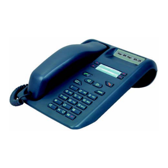
Nota : The sets followed by an asterisk do not appear any more in the catalogue from 2006. M720 set Figure 4.1 M720 set Installation Manual for digital sets - IP sets - SIP sets AMT/PTD/TR/0001/3/7/EN Installation of sets in the M7xx range... -
Page 38: Main Features
Figure 4.2 Front and bottom view of M720 set 4.1.1 Main features • one programmable key with LED indicator, • group listening with LED indicator, • on-hook dialling (as of R1.3), • mute function, • message/call indicator lamp, • direct voice mail recall by R key (when idle), •... -
Page 39: Advantages Of The M7Xx Range
Optional wall plate (M401 and M405). • One programmable key rather than 5 (M405). 4.1.4 Marketing codes Set no longer included in the catalogue. 4.1.5 Options Plate for wall mounting the M720 set. 4.1.6 Installation 4.1.6.1 Connections See connection diagram, section 12.2 4.1.6.2 Connection To the telephone network: by a 3.10 m long cord with an RJ45 type male connector for the wall end... -
Page 40: M725 Set
M725 set Figure 4.3 M725 set Figure 4.4 Front and bottom view of M725 set AMT/PTD/TR/0001/3/7/EN Installation Manual for digital sets - IP sets - SIP sets Page 4-4 05/2008 Installation of sets in the M7xx range... -
Page 41: Main Features
4.2.1 Main features • screen with 1 line x 16 characters, • 4 programmable keys with an LED each; these keys have two functions: programmable numbers or functions, search by name in the directory (in release 4.1 and later), • a green last number redial button used as the dynamic key "CALL"... - Page 42 4.2.4.3 Starting The M725 terminal is recognised in PBX software release 4.1 and later. Nevertheless, it may be used in previous releases of the software; in this case, it is recognised as a digital set on all the lists on which the connected set type appears. This behaviour may be corrected by declaring the M725 set type via an installer MMC.
-
Page 43: Figure 4.5 M730 Set
M730 terminal Figure 4.5 M730 Set Je 19 Oct 10:00 Assistante Filtrage M.Martin Renvoi Figure 4.6 Front and bottom view of M730 set Installation Manual for digital sets - IP sets - SIP sets AMT/PTD/TR/0001/3/7/EN Installation of sets in the M7xx range 05/2008 Page 4-7... -
Page 44: Options
4.3.1 Main features • screen with 1 line x 16 characters, • 4 programmable keys with LED indicators, • group listening with LED indicator, • mute function with LED indicator, • message/call indicator lamp, • direct voice mail recall by R key (in standby), •... -
Page 45: Installation
4.3.6 Installation 4.3.6.1 Connections See connection diagram, section 8.1.1. 4.3.6.2 Connection To the telephone network: by a 3.10 m long cord with an RJ45 type male connector for the wall end connection and an RJ11 type male connector for connection at the set end. To the telephone handset: by a coiled cable with an RJ9 type male connector at each end. - Page 46 FRANCAIS • Press Select the language using the navigator's up or down arrows (if required) ENGLISH Example: Press • Press 2 confirmation beeps, then back to the idle screen Nota : In case of error or change, to change the language, •...
-
Page 47: M740/M740E Set
M740/M740E set Figure 4.7 M740 set Figure 4.8 M740E set Installation Manual for digital sets - IP sets - SIP sets AMT/PTD/TR/0001/3/7/EN Installation of sets in the M7xx range 05/2008 Page 4-11... -
Page 48: Figure 4.9 Front View Of M740/M740E Sets
Figure 4.9 Front view of M740/M740E sets Figure 4.10 Bottom view of M740/M740E sets AMT/PTD/TR/0001/3/7/EN Installation Manual for digital sets - IP sets - SIP sets Page 4-12 05/2008 Installation of sets in the M7xx range... -
Page 49: Main Features
4.4.1 Main features • screen with 1 line x 16 characters, 10 programmable keys with indicators:LCD icons for the M740 set LEDs for the M740E set. • The last four programmable keys are for managing calls by name (in set software release 5.2A and later). -
Page 50: Marketing Codes
4.4.4 Marketing codes Reference Code M740E, Nordic handset, anthracite blue AMTD2730B M740E, Nordic handset, glacier white AMTD2730C Latin handsets are not longer included in the catalogue. M740 set is no longer included in the catalogue. 4.4.5 Options Plate for wall mounting the M740 set. 4.4.6 New features in release 4.1 In release 4.1 and later, the four lower programmable keys are used as functions key during a call... - Page 51 Procedure (Before R1.3) Once the set is connected, the screen of the M740 is displayed: M740 Ry.yxx-- SET LANGUAGE Nota : "SET LANGUAGE OK" remains displayed, forcing the user to select (if required) then validate the language. By default, the set is delivered in English, the first option proposed being "FRANCAIS". Only by pressing the red key it is possible to exit this mode without selecting a Attention : language, the standby screen displayed (date and time) being set to the PBX's...
- Page 52 4.4.7.4 Default settings upon delivery Current ring tone: Current ring volume: * Private directory ring tone: * Private directory ring volume: Contrast: Key beep: Micro headset: Group listening: Handset listening: Language before R1.3: English * As of R1.3 AMT/PTD/TR/0001/3/7/EN Installation Manual for digital sets - IP sets - SIP sets Page 4-16 05/2008 Installation of sets in the M7xx range...
-
Page 53: M760 Set
M760 set Figure 4.11 M760 set Figure 4.12 Front and bottom view of M760 set Installation Manual for digital sets - IP sets - SIP sets AMT/PTD/TR/0001/3/7/EN Installation of sets in the M7xx range 05/2008 Page 4-17... -
Page 54: Main Features
4.5.1 Main features • screen with 2 lines x 40 characters, • 5 interactive keys, • 20 programmable keys with LCD icons, • a proper alphabetical keyboard allowing search by name, • "Hands free" function, full duplex with LED indicator, •... -
Page 55: Options
4.5.5 Options A maximum of two extension modules can be connected to the M760: • either 2 M700/M710s, • or 1 M700/M710s + 1 M705/M715. Analogue options card, see section 6.6 IP cartridge, see section 5.9 4.5.6 Installation 4.5.6.1 Connections See connection diagram, section 12.2 4.5.6.2 Connection... -
Page 56: M760E Set
M760E set Figure 4.13 M760E set Figure 4.14 Front view of M760E set AMT/PTD/TR/0001/3/7/EN Installation Manual for digital sets - IP sets - SIP sets Page 4-20 05/2008 Installation of sets in the M7xx range... -
Page 57: Main Features
4.6.1 Main features The functions are the same as those offered by M760, see Section 4.5.1. The only difference lies in the signalling of the 20 programmable keys which is done via LCD on an M760E set, and via LCD icons on an M760 set. 4.6.2 Marketing Codes Reference... - Page 58 Procedure (before release 1.3): Once the set is connected, the screen of the M760 displays: M 760 -- R y.yxx-- For a set delivered CHOISISSEZ LA LANGUE DE VOTRE POSTE : with Azerty keypad Français English Deutsch Nederl. CHOOSE DISPLAY LANGUAGE: For a set delivered Français English...
- Page 59 4.6.4.4 Default settings on delivery Current ring tone: Current ring volume: *Current privileged ring tone: *Current privileged ring volume: Screen contrast: Key beep: Micro headset: Group listening: Handset listening: Language before R1.3: English with Qwerty keyboard French with Azerty keyboard * As of R1.3 Installation Manual for digital sets - IP sets - SIP sets AMT/PTD/TR/0001/3/7/EN...
-
Page 60: M760/M760E Attendant Console
M760/M760E Attendant Console 4.7.1 Recommendations for Operation as class B attendant console Information (M760/M760E and old range): Timeout for the ATDC to display its idle screen. By default this is 2.5 sec (value 250) and can be reduced to 0 for immediate display (CI048). ATDC deactivation timeout on no answer. - Page 61 4.7.2.1 As of R1.3 With ATDC declaration via MMC, the keys are programmed automatically, as in the diagram below OVERLOAD SIGNALLING MUTE CONSOLE ACTIVE MONITORING YOUR NUMBER 1 CALL SUPERVISION PSTN INC 1 MONITORING YOUR NUMBER 2 CALL SUPERVISION PSTN INC 2 MONITORING YOUR NUMBER 3 CALL SUPERVISION TIE LINE INC MONITORING YOUR NUMBER 4...
-
Page 62: M780 Set
M780 set Figure 4.15 M780 set Figure 4.16 Front and bottom view of M780 set AMT/PTD/TR/0001/3/7/EN Installation Manual for digital sets - IP sets - SIP sets Page 4-26 05/2008 Installation of sets in the M7xx range... -
Page 63: Main Features
4.8.1 Main features • tactile (touch-sensitive) screen, 24 lines x 40 characters (1/4 VGA), • 60 programmable keys, virtually accessible on the screen, • an alphabetical keyboard allowing search by name on the screen, • enhanced user-friendliness, • additional features: calculator, memo, •... -
Page 64: Installation
4.8.4 Installation This set can only be used as of system version V11.5. 4.8.4.1 Connections See connection diagram, section 12.2 See mains connection diagram, section 12.2. 4.8.4.2 Connection To the telephone network: by a 3.10 m long cord with an RJ45 type male connector for the wall end connection and an RJ11 type male connector for connection at the set end. - Page 65 Then M780 -- Ry.yxx-- Choose display language English Nota : "CHOOSE DISPLAY LANGUAGE" remains displayed, forcing user selection of the language, and screen calibration. Only by pressing the red key it is possible to exit this mode without selection, the Attention : standby screen displayed being set to the PBX's language.
- Page 66 Example: Press M780 -- Ry.yxx -- Choose display language Français Press You will hear 2 confirmation beeps, then automatic display of the first calibration screen: Press the centre of the cross located at the top left of the screen with your stylet to (re)calibrate your touch-sensitive screen.
- Page 67 4.8.4.4 To start as of R1.3 Recommendations As of R1.3, the set's language (label display managed locally by the set) synchronizes automatically with the system it is connected to (label display sent by the system in the country's language). Procedure Once the set is connected, the screen of the M780 displays for a few seconds: Then automatic display of the first calibration screen: Press the centre of the cross...
- Page 68 • confirm using the ACTIV. interactive key on an M760, the OK key on an M780, M740, M730. Nota : for an M720, just enter PROG99 within 5 seconds after power-up. • you will hear 2 confirmation beeps. Before R1.3:the terminal retrieves the first cut-in idle screen with the request for the choice of language to be made.
- Page 69 4.8.4.7 To set the handset audio profile This operation is used to adapt the audio characteristics (transmission/reception) of a set handset according to the system and line type. The available audio profiles are preset and fixed; the TX and RX gains of the handset are set in 3 dB steps with 9 options.
- Page 70 AMT/PTD/TR/0001/3/7/EN Installation Manual for digital sets - IP sets - SIP sets Page 4-34 05/2008 Installation of sets in the M7xx range...
-
Page 71: To Install Sets And Cartridges In The I7Xx Range
TO INSTALL SETS AND CARTRIDGES IN THE I7XX RANGE The i7xx range of IP sets includes: • the i740* set, • the i740N set, • the i760* set, • the i760E set, • the i780* set, • the IP cartridge to upgrade the M760 set to IP, •... - Page 72 5.1.2.2 Access to the i740/i740N configuration An initialisation phase is activated on power up. When initialisation is complete, a question mark appears on the left of the display. The installer then has 5 seconds to enter one of the following sequences: ("Prog"*1) to enter network parameters in the configuration menu, the first menu option "Phone number"...
- Page 73 5.1.2.3 Access to the i760/i760E configuration Once powered up, the set displays i760/i760E on the 1st line and the " -- Rxyxyx-- " software version of the set on the second line. The set then displays a question mark "?" on the 1st line and i760/i760E followed by the " -- Rxyxyx-- "...
- Page 74 5.1.2.4 Access to the i780 configuration Once powered up, the set displays i780 on the 1st line along with the software version The set's " -- Rxyxyx-- " on the 2 line. The set then displays a question mark. " ? " on the 1st line and i780 followed by the software version " -- Rxyxyx-- " of the cartridge on the line.
- Page 75 5.1.2.5 Working principle of the i740/i740N/i760/i760E/i780 editor The editor is used to enter values in the form of digits, and a dot "." with the "*" key on the dial keypad for IP addresses. These values can contain 1 to 12 digits maximum, depending on the associated function.
- Page 76 5.1.2.6 To configure the starting mode for i7xx sets The starting mode of the i7xx sets requires prior knowledge of the site network. The various starting modes available are: • Manual, • Partial DHCP mode, • Full DHCP mode. Manual mode All identification parameters related to network configuration must be provided by the site operator.
-
Page 77: Configure The Pbx
5.1.3 Configure the PBX The steps required to declare an i7xx IP set on the PBX are the following: • Unlock IP SET functions • Configure the IP access point • Create at least one general purpose set logical subscriber •... -
Page 78: Quality Of Service
• DCF 459 for the random time range before a new attempt to open a TCP/IP session. This parameter is encoded over 16 bits, i.e. one byte for the minimum value, and one byte for the maximum value. • DCF 429 for the time between two audits (10ms unit). The audit is automatically deactivated if the value of this parameter is 0. - Page 79 Poste i7xx Tagged 802.1q Untagged 802.3 The "telephony" VLAN is tagged by the i7xx set. It can be configured by full DHCP, or in manual configuration. After the i7xx set has powered up and the ? is displayed, enter *1 for the i760 and i780 or PROG*1 for the i740/i740N.
-
Page 80: Specific Functions For Ip Sets
Specific functions for IP sets 5.2.1 PC switch IP sets have an RJ45 socket for connection to a PC, which makes it possible to connect the set and PC to the same network socket. The IP set is inserted between the PC and the network. It manages both voice and data traffic using an Ethernet switch that is also called a PC switch. -
Page 81: Encryption
5.2.4 Encryption Principle: To prevent calls from being tapped on the IP network, voice is encrypted between two IP points; each of these points may be an IPDS (i740, i760,i780 ) or a VoIP set. Calls may be encrypted end to end or partially. The encryption algorithm is resident on IPDSs (i740, i760, i780), or on NeXspan (PT2, PVI) devices, on Call server, and F6 CPU card (PTX). - Page 82 • Encryption keys = enter the 32-character CMEK key and the 28-character CMSK key => The saved keys are no longer visible (* appears) and a signature (date + edition) appears, with the functional status “In Service”. For slave sites: •...
-
Page 83: I740 Set
i740 set Figure 5.1 i740 set Figure 5.2 Front and bottom view of the i740 set Installation Manual for digital sets - IP sets - SIP sets AMT/PTD/TR/0001/3/7/EN To install sets and cartridges in the i7XX range 05/2008 Page 5-13... -
Page 84: Main Features
5.3.1 Main features • screen with 1 line x 16 characters, • 10 programmable keys with LCD icons, • "Hands free" function, full duplex with LED indicator, • mute function with LED indicator, • message/call indicator lamp, • direct voice mail recall by R key (in standby), •... - Page 85 5.3.4.3 Default settings on delivery Current ring tone: Current ring volume Private directory ring tone Private Private directory ring volume Contrast Key sound Headset microphone Group listening Handset listening Installation Manual for digital sets - IP sets - SIP sets AMT/PTD/TR/0001/3/7/EN To install sets and cartridges in the i7XX range 05/2008 Page 5-15...
- Page 86 5.3.4.4 Network configuration parameters Attention : This procedure concerns the i740 sets with a software release lower than R5.3c. From R5.3c, the parameters of configuration are identical to those of the i740N set. AMT/PTD/TR/0001/3/7/EN Installation Manual for digital sets - IP sets - SIP sets Page 5-16 05/2008 To install sets and cartridges in the i7XX range...
- Page 87 Installation Manual for digital sets - IP sets - SIP sets AMT/PTD/TR/0001/3/7/EN To install sets and cartridges in the i7XX range 05/2008 Page 5-17...
- Page 88 Important notes: • Press to move to the next option, regardless of whether you are on a label field or on an option entry field (that has or has not been completed). • Press when on the first "Phone number" option to directly access the last "VLAN Id Activation"...
- Page 89 5.3.4.5 Ethernet configuration parameters Attention :This procedure concerns the i740 sets with a software release lower than R5.3c. From R5.3c, the parameters of configuration are identical to those of the i740N set. Nota : By default, the set is set to autonegotiation, and adapts to the relevant LAN and PC configurations.
- Page 90 5.3.4.6 To view the configuration The configuration parameters can be displayed with the set in standby or calling, using the keystroke ("Prog"*2). This keystroke enables all the LAN and Ethernet configuration parameters to be viewed. This function is managed locally. The programmed parameters can be viewed, but not modified.
- Page 91 Installation Manual for digital sets - IP sets - SIP sets AMT/PTD/TR/0001/3/7/EN To install sets and cartridges in the i7XX range 05/2008 Page 5-21...
- Page 92 5.3.4.7 View the identification parameters An initialisation phase is activated on power up. When initialisation is complete, a question mark appears on the left of the display. The installer then has 5 seconds to enter the keystroke - - ("Prog"*5) that opens the viewing menu, the first parameter "Phone version"...
- Page 93 5.3.4.9 To log out – prior to r3.2 The purpose of the Log out procedure is to allocate another number to a logged set. To log out a set, the following operations must be carried out: • Unplug and plug the set back in. An initialisation phase is activated (at the end of this initialisation phase, a question mark is displayed to the left of the display) •...
- Page 94 5.3.4.10 Login/logout function in release 3.2 and later In release 3.2 and later, the login/logout function is used to assign another number to an already logged set. This function is implemented by using feature access codes *44 to retrieve subscriber rights from another set, and #44 to deactivate them.
-
Page 95: I740N Set
i740N set Figure 5.3 i740N set Figure 5.4 Front and bottom view of the i740N Installation Manual for digital sets - IP sets - SIP sets AMT/PTD/TR/0001/3/7/EN To install sets and cartridges in the i7XX range 05/2008 Page 5-25... -
Page 96: Main Features
5.4.1 Main features • screen with 1 line x 16 characters, • 10 programmable keys, each with an LED, • 4 of these keys are used to search by name in the directory (in release 4.1 and later), • a green last number redial button used as the dynamic key "CALL" during a directory search, •... -
Page 97: Installation
5.4.4 Installation 5.4.4.1 Connections Refer to the network connection diagram in section 12.1.2. If required, refer to the mains connection diagram, section 12.2.4.3. 5.4.4.2 Connections To the LAN: using an Ethernet cable (remote supply possible via the LAN). Set of 10 Ethernet cables sold in the catalogue under reference HT1455A. Nota : If the cord is sleeved, a DH520A adapter must be used. - Page 98 5.4.4.4 Network configuration parameters Attention : this procedure concerns the i740N and i740 sets with a software release at least equal to R5.3c. AMT/PTD/TR/0001/3/7/EN Installation Manual for digital sets - IP sets - SIP sets Page 5-28 05/2008 To install sets and cartridges in the i7XX range...
- Page 99 Important notes: • Press to move to the next option, regardless of whether you are on a label field or on an option entry field (that has or has not been completed). • Press when on the first "Phone number" option to directly access the last "VLAN Id Activation"...
- Page 100 5.4.4.5 Ethernet configuration parameters Attention : this procedure concerns the i740N and i740 sets with a software release at least equal to R5.3c. Nota : By default, the set is set to autonegotiation, and adapts to the relevant LAN and PC configurations (PC port is idle).
- Page 101 5.4.4.6 To view the configuration The configuration parameters can be displayed with the set in standby or calling, using the keystroke ("Prog"*2). This keystroke enables all the LAN and Ethernet configuration parameters to be viewed. This function is managed locally. The programmed parameters can be viewed, but not modified.
- Page 102 AMT/PTD/TR/0001/3/7/EN Installation Manual for digital sets - IP sets - SIP sets Page 5-32 05/2008 To install sets and cartridges in the i7XX range...
- Page 103 5.4.4.7 Viewing the identification parameters The installer enters the sequence - - ("Prog"*5) to enter the display menu; the menu's first parameter "Phone version" is displayed. 5.4.4.8 To start for the first time or to restart When starting for the first time, or when restarting after unplugging, if the i740N set has not transmitted its number and password, a system identification phase is started: •...
- Page 104 5.4.4.9 Logging out – before R3.2 The purpose of the Log out procedure is to allocate another number to a logged set. To log out a set, the following operations must be carried out: • Unplug and plug the set back in. An initialisation phase is activated (at the end of this initialisation phase, a question mark is displayed to the left of the display) •...
- Page 105 5.4.4.10 Login/logout Function – in release 3.2 and later In release 3.2 and later, the login/logout function enables you to assign another number to a set that is already logged on. This function is implemented by using feature access codes *44 to retrieve subscriber rights from another set, and #44 to deactivate them.
-
Page 106: I760/I760E Set
i760/i760E set Figure 5.5 i760/i760E set Figure 5.6 Front view of the i760/i760E set AMT/PTD/TR/0001/3/7/EN Installation Manual for digital sets - IP sets - SIP sets Page 5-36 05/2008 To install sets and cartridges in the i7XX range... -
Page 107: Main Features
Figure 5.7 Bottom view of the i760/i760E set 5.5.1 Main features • screen with 2 lines x 40 characters, • 5 interactive keys, • 20 programmable keys with indicators: LCD icons for the i760 set, LEDs for the i760E set •... -
Page 108: Marketing Codes
5.5.2 Marketing codes Reference Code i760E, Nordic handset, anthracite blue, AZERTY keypad AMTD0330B i760E, Nordic handset, anthracite blue, QWERTY keypad AMTD0335B i760E, Nordic handset, glacier white, AZERTY keypad AMTD0330C i760E, Nordic handset, glacier white, QWERTY keypad AMTD0335C The sets are marketed without powered supply units. The latin handsets are not any more in the catalogue. - Page 109 5.5.4.3 Default settings on delivery Current ring tone: Current ring volume *Preferred ring tone: *Preferred ring volume: Screen contrast Key sound Headset microphone Group listening Handset listening Installation Manual for digital sets - IP sets - SIP sets AMT/PTD/TR/0001/3/7/EN To install sets and cartridges in the i7XX range 05/2008 Page 5-39...
- Page 110 5.5.4.4 Network configuration parameters Attention :This procedure concerns the sets upper or equal to software release R5.3c. The previous release do not display some parameters (eg: backup number or 2 PBX IP address). AMT/PTD/TR/0001/3/7/EN Installation Manual for digital sets - IP sets - SIP sets Page 5-40 05/2008 To install sets and cartridges in the i7XX range...
- Page 111 Important notes: • Press when on the first "Phone number" option to directly access the last "VLAN Id Activation" option (if option = 0) or "Priority" (if option = 1) . • You can validate with at any time, even if only one field has been modified, you will hear two validation beeps.
- Page 112 5.5.4.5 Ethernet configuration parameters This procedure concerns the sets upper or equal to software release R5.3c. The previous release do not display some parameters (eg:PC isolate) Nota : By default, the set is set to autonegotiation, and adapts to the relevant LAN and PC configurations (PC port is idle).
- Page 113 5.5.4.6 Viewing the identification parameters After power up, wait for the set to display a question mark. The installer then has 5 seconds to enter the * 5 sequence to open the identification parameter viewing menu, the first parameter is displayed. Installation Manual for digital sets - IP sets - SIP sets AMT/PTD/TR/0001/3/7/EN To install sets and cartridges in the i7XX range 05/2008...
- Page 114 5.5.4.7 To start for the first time or to restart When starting for the first time, or when starting after logging out (if the i760/i760E has not sent its number and password), the system sends a prompt to enter the directory number. After entering the number, a password entry prompt is displayed.
- Page 115 5.5.4.8 To log out To log out a set, the following operations must be carried out: • Unplug and plug the set back in. An initialisation phase is activated (at the end of this initialisation phase, a question mark is displayed to the left of the display) •...
- Page 116 5.5.4.9 Summary of installer codes used Access condition: Code: Function: After power up, at the end of the Configuring network parameters initialisation period, when "?" is displayed and within 5s In standby and during a call Viewing the configured parameters After power up, at the end of the Viewing the identification parameters initialisation period, when "?"...
-
Page 117: I780 Set
i780 set Figure 5.8 i780 set Figure 5.9 Front and bottom view of the i780 set Installation Manual for digital sets - IP sets - SIP sets AMT/PTD/TR/0001/3/7/EN To install sets and cartridges in the i7XX range 05/2008 Page 5-47... -
Page 118: Main Features
5.6.1 Main features • tactile (touch-sensitive) screen, 24 lines x 40 characters (1/4 VGA), • 60 programmable keys, virtually accessible on the screen, • an alphabetical keyboard allowing search by name on the screen, • enhanced user-friendliness, • additional features: calculator, memo, •... -
Page 119: Installation
5.6.4 Installation 5.6.4.1 Connections Refer to the network connection diagram in section 12.2.3. If required, refer to the mains connection diagram, section 12.2.4. 5.6.4.2 Connection To the LAN: using a Ethernet cord not supplied (remote supply possible via the LAN). Set of 10 Ethernet cables:HT1455A. - Page 120 5.6.4.4 Network configuration parameters The procedure is similar to the i760/i760E and simply transposed to the virtual PBX zone of the i780 screen, also. Furthermore, only the first screens are shown below as an example. AMT/PTD/TR/0001/3/7/EN Installation Manual for digital sets - IP sets - SIP sets Page 5-50 05/2008 To install sets and cartridges in the i7XX range...
- Page 121 Etc … idem i760 5.6.4.5 Ethernet configuration parameters The procedure is similar to the i760/i760E set and simply transposed to the virtual PBX zone of the i780 screen. 5.6.4.6 Viewing the identification parameters The procedure is similar to the i760 set and simply transposed to the virtual PBX zone of the i780 screen.
- Page 122 5.6.4.9 Summary of installer codes used Access condition: Code: Function: After power up, at the end of the Configuring network parameters initialisation period, when "?" displayed and within 5s In standby and during a call Viewing the configured parameters After power up, at the end of the Viewing the identification parameters initialisation period,...
-
Page 123: To Restore The Default Factory Settings
To restore the default factory settings This operation erases all local programming that has been carried out in the set (logs, rings, directories, programmed keys…) and initialises the set with the same configuration parameters as on delivery for the country concerned. Secret code and programmed keys are not set back to the default value because they are managed by the system. -
Page 124: To Set The Handset's Audio Profile
To set the handset's audio profile This operation is used to adapt the audio characteristics (transmission/reception) of a set handset to suit the system (PBX) and line type. The available audio profiles are preset and fixed; the TX and RX gains of the handset are set in 3 dB steps with 9 options. -
Page 125: Ip Cartridge
IP cartridge Figure 5.10 IP cartridge for the M760 set Figure 5.11 IP cartridge for the M780 set 5.9.1 Description The IP cartridge is used to connect the M760 and M780 sets to a LAN. It is a PCB that is inserted into the set's cartridge slots. Its purpose is to provide transparent operation for the set in respect to the network: all commands sent by the PBX are sent to the set. -
Page 126: Marketing Codes
• one version for M780 sets with a 275 mA supply. Both cartridge versions operate on 220-Volt mains, with a 48-Volt power supply. 5.9.2 Marketing codes Reference Code IP cartridge for the M760 set HR1855A IP cartridge for the M780 set HR1970A 5.9.3 Installation... - Page 127 the sleeve. • Fit the IP cartridge into its slot, and secure it (3 securing screws). • Lift the cover then connect the cartridge link to the set connector. • Close the cover. • Remove the two covers on the rear panel by pushing them outwards from the inside. •...
- Page 128 AMT/PTD/TR/0001/3/7/EN Installation Manual for digital sets - IP sets - SIP sets Page 5-58 05/2008 To install sets and cartridges in the i7XX range...
-
Page 129: M7Xx And I7Xx Set Options
M7XX AND I7XX SET OPTIONS M700 extension Nota : The extension M700 is not any more marketed. Figure 6.1 M700 extension with M760, M760E or i760 set and with M780 or i780 set Ligne 1 Assistante M.Martin Superv. Ligne 2 Superv. -
Page 130: Description
6.1.1 Description The M700 extension is a unit that can be joined to the M760, M760E, M780, i760/i760E and i780 sets to form an aesthetically pleasing unit. It is a module that contains 20 additional keys with no back-lighting. The 20-button keypad is identical to the M760, M760E or i760/i760E keypad. -
Page 131: M710 Extension
M710 extension 6.2.1 Description The only difference between the M710 extension and the M700 extension is that the 20 programmable keys are monitored by LEDs instead of LCD icons. The other specifications remain unchanged. 6.2.2 Marketing codes Reference Code M710, anthracite blue TD2970B M710, glacier white TD2970C... - Page 132 6.2.4.2 Connection • The extension module is connected by an 8-pin RJ45 female connector. • Connection precautions: M760/M760E: Unplug the line, then connect the extension to the set and plug the line into the set, in this order. M780: Unplug the mains and the line, then, in the following order, connect the extension to the set, plug the line into the set and finally, plug the mains into the extension.
-
Page 133: M705 Extension
M705 extension Nota : The extension M705 is not any more in the catalogue. Figure 6.3 M705 extension with M760, M760E or i760 set and with M780 or i780 set Figure 6.4 Front and bottom view of the M705 extension Installation Manual for digital sets - IP sets - SIP sets AMT/PTD/TR/0001/3/7/EN M7xx and I7xx set options... -
Page 134: Description
6.3.1 Description The M705 extension is a unit that can be joined to the M760, M760E, M780, i760, i760E and i780 sets to form an aesthetically pleasing unit. It is a module containing 20 additional keys without back-lighting, the top part of which can hold a DECT handset charger (type MC900). -
Page 135: M715 Extension
M715 extension 6.4.1 Description The only difference between the M715 extension and the M705 extension is that the 20 programmable keys are monitored by LEDs instead of LCD icons. The other specifications remain unchanged. 6.4.2 Recommendation concerning the power supply unit M760, M760E and M780 sets This configuration requires an external power supply when connected to the M760 or M760E. -
Page 136: Installation
6.4.5 Installation 6.4.5.1 Connections The connections are made using 2 RJ45 male connectors on the input and output. This connector is used to connect a module to the set or to connect an M705 to an M700. 6.4.5.2 Connection The extension module is connected by an 8-pin RJ45 female connector. INTERFACE Alimentation 12V vers poste 20 Touches... -
Page 137: Wall Mounting Plate
6.5.1 General information This mounting plate is used to install an M720, M725, M730, M740 or M740E on a wall using a kit (packet containing 2 screws + 2 pegs as well as an attachment lug for the M725 terminal). -
Page 138: Template
6.5.2 Template 6.5.3 Marketing code Reference Code Optional wall-mounting bracket kit HT1423A AMT/PTD/TR/0001/3/7/EN Installation Manual for digital sets - IP sets - SIP sets Page 6-10 05/2008 M7xx and I7xx set options... -
Page 139: Analogue Options Board
Analogue options board Figure 6.6 Analogue options board 6.6.1 Description The analogue option card kit consists of: • a daughter card that can be installed at the rear of an M760, M760E or M780, • a connection link to the base set. The daughter card has 3 connectors: •... -
Page 140: Options
6.6.3 Options T connector (RJ45) to group the line cord and ringing cord. S ta nda rd ada pte r C o nne cto r a nd co rd fo r set line W all so cket 8 pts ma le -->2 x 8 pts female eq uip ped 4 2 cab le s use d S et... - Page 141 6.6.4.2.2 Daughter card connectors 6.6.4.2.2.1Stereo jack connector The diameter of the jack is 3.5 mm. 6.6.4.2.2.2Minitel/MODEM connector The switch located on the card is used to configure several types of connection: • Switch in the upper position (on the side with the 2 connectors and jack), for configurations that are compatible with the current Minitel base, •...
-
Page 142: Electrical Characteristics
6.6.4.2.2.3External ringing output connector 6.6.5 Electrical characteristics MODEM access: • output level: 150 mV RMS typ. with 3% distortion • output impedance: 790 Ohms typ. • DC open-circuit voltage: 9.0 V typ. • max. available DC current: 10 mA typ. Audio access: •... -
Page 143: I220 Sip Set
I220 SIP SET I220 SIP sets are sets owner. As of R4.1 they are managed by the NeXspan Communication Server of Call Manager. A SIP gateway is needed (GSI). This gateway is integrated in the Call Manager and allows to convert SIP messages into messages can be understood by the Call Manager and vice-versa. -
Page 144: Starting And Configuring The I220 Sip Set
STARTING AND CONFIGURING THE i220 SIP SET 7.2.1 PBX Pré-requisites Following actions must be carried out on the Call Manager: • Activation of Windows feature: "Call Server SIP Gateway (GSI)". • Déclaration of IP equipmetns in the Call Manager. • For more details, see NeXspan Communication Server - Installation and Configuration Guide (section 1.6.2). - Page 145 7.2.3.1 Configuring the set Installation Manual for digital sets - IP sets - SIP sets AMT/PTD/TR/0001/3/7/EN i220 SIP set 05/2008 Page 7-3...
- Page 146 AMT/PTD/TR/0001/3/7/EN Installation Manual for digital sets - IP sets - SIP sets Page 7-4 05/2008 i220 SIP set...
-
Page 147: Figure 7.2 Enter The Password
7.2.3.2 Updating of the set software via web interface Attention :The Web interface is available only when the i200 set is in configuration mode. From a network PC, open Internet Explorer: • Enter the IP address of the i220 set: http://10.3.2.57 •... - Page 148 To go from another web page, select one of the following items: Admin / Network / SIP / Phone / Advanced / Speeddial / Info / Upload For a detailed description of Web interface, refer to Administrator Guide of i220 IP set (see § 1.6.1). Note : After each change of the Web page, click on Save to make a backup.
- Page 149 • Select Upload to update the i220 set software Click on Browse… button to find update file i220_fw.bin, then click on Upload. • Select Info to view the current IP set firmware version and to make sure that the settings are corrects.
- Page 150 AMT/PTD/TR/0001/3/7/EN Installation Manual for digital sets - IP sets - SIP sets Page 7-8 05/2008 i220 SIP set...
-
Page 151: Sip Phones 480I, 9112I And 9133I
SIP phones 480i, 9112i and 9133i are used for telephone calls on an IP network, using the SIP signalling protocol. They are managed from PBX release 4.2. Release 1.4.1 of the firmware for AASTRA SIP phones 480i, 9112i and 9133i is compatible with NeXspan R4.2 solution: •... -
Page 152: Installing Sip Phone 480I
8.1.3 Installing SIP phone 480i The connections are described in the installation guide (see Section 1.6.1) SIP phone 9112i Figure 8.2 SIP phone 9112i 8.2.1 Description of SIP phone 9112i A detailed description of the phone is given in the user guide (see Section 1.6.1) 8.2.2 Sales code for SIP phone 9112i The sales code for SIP phone 9112i with mains unit is A171001311055. -
Page 153: Sip Phone 9133I
SIP phone 9133i Figure 8.3 SIP phone 9133i 8.3.1 Description of SIP phone 9133i A detailed description of the phone is given in the user guide (see Section 1.6.1) 8.3.2 Sales code for SIP phone 9133i The sales code for SIP phone 9133i with mains unit is A172001311055. 8.3.3 Installing SIP phone 9133i The connections are described in the installation guide (see Section 1.6.1) -
Page 154: I, 9112I And 9133I Sip Set Telephony Features
480i, 9112i and 9133i SIP set telephony features LEGENDE X (fonctionnal or activated by key or mire) C (activated by code) G (activated by management) Outbound call Access 9112i 9133i 480i rights - General Set-based AID/IID Call-based AID/IID Display of calls forwarded from the called set - Dialling Q23 dialling (for external modem) Q23 overdialling transmitted by the terminal... - Page 155 Outbound call Access 9112i 9133i 480i rights Interaction with voicemail box Interactivity with voice mail system through the display Indication of waiting voice messages Alphanumeric input Open dialling Dialling with edition - Access rights Dedicated outbound sets (cannot be called) Limitation on external calls Limitation on all calls Limitation on regional calls...
- Page 156 Call in progress Access 9112i 9133i 480i rights Hold Call pick-up Stoppable voice prompt Enquiry call Alternate Three-way conference Transfer after communication Transfer to busy 1 set Transfer to free set Go Back Pager (simple or meeting) Transfer to voice mail Call parking or parked call recovery suspension of conference park Record conversations...
- Page 157 Incoming call Access 9112i 9133i 480i rights Hunt group call pick-up Common bell pickup Fixed head groups Mobile head groups Longest-idle-time set distribution group General bell hunt group Multi-hunt group / super-hunt group distribution Assistance among hunt groups Simple intercom as supervisor may be supervised restricted intercom characters...
- Page 158 Set engaged in a communication Access 9112i 9133i 480i rights Divert a call without interrupting on-going call Offer / intrusion / third-party intrusion Offer / intrusion / third-party intrusion: from an IP terminal Offer / intrusion / third-party intrusion: to an IP terminal Override mandatory (offer/intrusion) Discrete listening...
-
Page 159: I, 9112I And 9133I Sip Set Technical Characteristics
Multiple CCOs Access 9112i 9133i 480i rights multiline subscribers Multi-appearance (multi-key) Connection of two calls Enquiry call separation Selecting the number of CCOs Manager line Call signal Consulting a waiting call Pick-up a waiting call Protection against waiting calls 480i, 9112i and 9133i SIP set technical characteristics Ergonomics Access 9112i... - Page 160 Miscellaneous Access 9112i 9133i 480i rights Technical Web administration User Web Administration TFTP Technical parameter loading TFTP User parameter loading TFTP Firmware loading Phone-park administration tool SNTP SNMP G711 codec G729 codec G723.A/B codec Marking DSCP 802.3af remote power supply IEEE 802.1p QOS IEEE 802.1Q VLAN Tagging Listing of SIP sets...
- Page 161 Features offered by the 9112i 9133i 480i telephone Multi-line 3 lines 9 lines Direct memory keys 2 keys 7 keys 6 keys Indirect memory keys Line seizure without lifting the handset Screen 3 lines x 16 characters 3 lines x 16 characters 8 lines x 20 characters Visual display of call on hold, mute, and message...
-
Page 162: Architectures Of Nexspan With Sip Phones
Architectures of NeXspan with SIP phones The SIP phones are declared in the iPBX (NCS or NeXspan), but are connected via the SIP access point. This SIP access point can be hosted by NCS, the IPS card of a NeXspan or NeXspan SIP Access Point (NSAP). -
Page 163: Architecture Using The Sip Access Point Of The Nexspan Ips Card
8.7.2 Architecture using the SIP access point of the NeXspan IPS card. Figure 8.5 Architecture using the SIP access point of the NeXspan IPS card. The IPS card is powered up via the back plane, but it is not managed by the iPBX. It provides the SIP access point and a TFTP server. -
Page 164: Architecture Using The Sip Access Point In The Nsap Of Nexspan 500
8.7.3 Architecture using the SIP access point in the NSAP of NeXspan 500 Figure 8.6 Architecture using the SIP access point in the NSAP of NeXspan 500 NSAP is a server under Linux (Red Hat ES4), which hosts the SIP access point for SIP phones and the SIP trunk. -
Page 165: Aastra Sip Phone Configuration Modes
• By loading the configuration files via DHCP/TFTP. Aastra Matra recommends configuring the SIP phones using the files aastra.cfg and @MAC.cfg, to allow rational management of a pool of phones. However, to quickly implement some phones on a breadboard, you may envisage direct configuration on the phone or via the WEB interface. -
Page 166: Direct Configuration On The Phone
8.8.1 Direct configuration on the phone You can access the manual configuration of the phone via the “Options” key. Location of the “Options” key on phone 480i: A password is required for the parameters reserved for the administrator. By default, this password is 22222. - Page 167 8.8.1.2 Entering the basic SIP parameters ‘Options’ key ‘9-SIP parameters’ Display 1- Proxy IP 2- Proxy port 3- IP address 4- Port address 5- Save 6- Username … 8- Screen name In this example, the configuration will be: • Proxy IP=192.168.65.2 •...
-
Page 168: Configuration Via The Web Interface
8.8.2 Configuration via the WEB interface First define the phone IP address, either manually or via DHCP. Connect via a WEB browser: http://@IP_SIP_phone • Access in User mode: Username: user Password: 11111 • Access in Administrator mode: Username: admin Password: 22222 8.8.2.1 Restoring the phone’s factory settings Operation... -
Page 169: Figure 8.9 Configuring The Phone's Basic Network Settings
8.8.2.2 Configuring the phone’s basic network settings Advanced settings>Network Confirm DHCP to automatically obtain the address, or enter the SIP phone’s IP address, subnet mask and default gateway. Figure 8.9 Configuring the phone’s basic network settings Installation Manual for digital sets - IP sets - SIP sets AMT/PTD/TR/0001/3/7/EN SIP PHONEs 480i, 9112i and 9133i 05/2008... -
Page 170: Figure 8.10 Configuring The Sip Parameters
8.8.2.3 Configuring the SIP parameters Advanced Settings>Global SIP This window allows you to define the phone’s global settings. • The basic settings are: • Screen name: name displayed on the phone screen • Phone number: SIP subscriber number • Proxy Server/Registrar Server: SIP access point IP address •... -
Page 171: Figure 8.11 Configuring The Download Server
8.8.2.4 Configuring the download server Advanced Settings>Configuration Server This window allows you to enter the IP address of a TFTP server so as to download files to the phone (for updating the firmware, configuration files, directory, etc.). Using DHCP (recommended) enables you to automatically load the TFTP server address. Figure 8.11 Configuring the download server Installation Manual for digital sets - IP sets - SIP sets AMT/PTD/TR/0001/3/7/EN... -
Page 172: Figure 8.12 Updating The Sip Phone Firmware Manually
8.8.2.5 Updating the SIP phone firmware manually Advanced Settings>Firmware Update You can update the firmware manually to specify a filename other than the default name used by the automatic update. The specified file must be present in the default TFTP server directory. Figure 8.12 Updating the SIP phone firmware manually AMT/PTD/TR/0001/3/7/EN Installation Manual for digital sets - IP sets - SIP sets... -
Page 173: Configuration Through A Download Server
Format of files used for downloading: • Firmware: <phone type>.st (example: 480i.st) • General phone configuration: aastra.cfg • Specific phone parameter file: @MAC.cfg (example: 00085D3A2451.cfg) Therefore, you will use the configuration directly on the phone or via the WEB interface for a reduced number of phones. -
Page 174: Using The Solution With Sip Phones
Using the solution with SIP phones 8.9.1 Deployment phases AMT/PTD/TR/0001/3/7/EN Installation Manual for digital sets - IP sets - SIP sets Page 8-24 05/2008 SIP PHONEs 480i, 9112i and 9133i... -
Page 175: Configuring The Dhcp Server
8.9.2 Configuring the DHCP server Using a DHCP server to assign IP addresses to the phones is not obligatory, but it simplifies the management of addresses and reduces the risk of errors (IP address duplications, etc.). You can use the DHCP server available on Windows 2000 or 2003 servers, a server, or use a free DHCP software solution, for example TurboDHCP. - Page 176 Check the address range distributed by the ‘SIP phones’ range in the ‘Address pool’ menu. Display the options associated with the address range of the ‘SIP phones' range in the ‘Extended options’ menu. 8.9.2.3 Adding option 066 to specify the IP address of a TFTP server Action Configure options Search for option 066, check the associated box, enter the server IP...
-
Page 177: Configuring The Tftp Server
On the other hand, the time to update the phone in automatic mode, using the ‘auto resync mode’ and ‘auto resync time’ instructions in the configuration file aastra.cfg ou @MAC.cfg, must be set to 30 min. - Page 178 8.9.3.2 Configuring the TFTP server provided with the NCS software The TFTP server PumpKIN (freeware) is delivered with the NCS software since version G2J. The TFTP server PumpKIN is installed as a service (TFTP-PumpKIN). In the Services window, select the TFTP-PumpKIN application. Right-click on the line TFTP-PumpKIN and select Properties.
- Page 179 Note : When installing Call Manager, the directory c:\Program Files\Call Server\Call Manager\tftp is empty. The configuration files, language packs and firmware of SIP phones 480i, 9112i and 9133i are available in the directory SIP_Sets/480i of NCS CDROM. These files have to be copied manually to the directory c:\Program Files\Call Server\Call Manager\tftp in case of a new installation.
- Page 180 TFTP-PumpKIN service. 8.9.3.3 TFTP server provided with the IPS card software Caution: The IPS card TFTP server can only be used to download Aastra SIP phones (9112i, 9133i, 480i). The IPS card TFTP server is the atftpd server distributed by Debian.
- Page 181 In order not to disturb the working of the NSAP, we recommend that you lower the priority given to the TFTP server. In the file "/etc/xinetd.d/tftp", add the following line in bold: # default: off # description: The tftp server serves files using the trivial file transfer \ # protocol.
-
Page 182: Using Filezilla
8.9.4 Using FileZilla FileZilla is a secure FTP client in graphic mode, used to handle phone configuration files: these files are created or modified on a PC in Windows, then transferred via FileZilla to the \tftpboot directory of the IPS card or NSAP. After installing the software, configure a site: ‘File’>‘Site manager’. - Page 183 8.9.4.1 Updating the phone firmware • Back up the IPS card firmware on a directory on the PC. • Copy the new firmware to the \tftpboot directory of the remote site. Respect the firmware filenames: • 9112i.st • 9133i.st • 480i.st 8.9.4.2 Modifying SIP phone configuration files...
-
Page 184: Ntp Server
Time is set on the phones via an NTP server. The NTP server IP address must be configured in the general parameters (the file aastra.cfg) or specific parameters (file @MAC.cfg) of the SIP phones. Example of NTP server: Absolute Time Server 2.2. -
Page 185: Configuring Sip Phones Through Configuration Files
8.9.6.1 Content of the configuration file ‘aastra.cfg’ The configuration file aastra.cfg configures the data common to SIP sets 480i, 9133i and 9112i. The data below is communicated as examples and presents most of the parameters of the SIP phones to configure for the NeXspan solution. - Page 186 # aastra.cfg dhcp: 1 # Validated DHCP: this configuration is recommended on NeXspan # If a fixed IP address is used, the parameters will be defined in the @MAC.cfg files. admin password: 22222 # Administrator password for WEB access:22222 user password: 0000...
- Page 187 language 4: lang_es.txt# load spanish language ########################################################################### sip transport protocol: # UDP sip rtp port: 3000 # Default port: 3000 ########################################################################### # DTMF configuration ########################################################################### sip out-of-band dtmf: 0 # This value is obligatory for NeXspan. sip dtmf method: 1 # The value 1 is obligatory for NeXspan (method: SIP INFO) live dialpad: 1...
- Page 188 #sip customized codec: payload=8;ptime=20;silsupp=off,payload=18;ptime=20;silsupp=off # coding laws (payload=8 G711.A, 0 for G711 mu, 18 for G729) sip mode: 0 # The value 0 is obligatory for NeXspan ########################################################################### # Loading a directory in the phone ########################################################################### directory disabled: 0 # The private directory is accessible on the phones. directory 2: AMT_NeXspan_directory.txt# Loading private directory file (200 items max) # Format of the directory file ‘AMT_NeXspan_directory.txt’: # Surname1 First name, number1, 1, private...
- Page 189 traffic is only marked between the phone and the network. QoS eth port 0 priority: 6 # Priority level 2 for phone traffic (ToIP) QoS eth port 1 priority: 0 # Priority level 2 for Data traffic from the PC #non-ip priority: 0 # Priority of non-IP packets # If the TOS priority map is not defined, correspondence between DiffServ and 802.1Q:...
- Page 190 603 # NeXspan subscriber number #sip proxy ip: 136.10.1.138 # GSI IP address if different from that of the file aastra.cfg #sip registrar ip: 136.10.1.138 # GSI IP address if different from that of the file aastra.cfg...
- Page 191 … #sip line9 registrar ip: 136.10.1.138 #sip line1 registrar port: 5060 # port 5060 _ line 1 … #sip line9 registrar port: 5060 #sip line1 registration period: 3600 # The value 3600 is obligatory for NeXspan … #sip line9 registration period: 3600 #sip line1 auth name: # No authentication for NeXspan …...
- Page 192 #line5 ring tone: 4 #line6 ring tone: 5 #line7 ring tone: 0 #line8 ring tone: 1 #line9 ring tone: 2 tone set: FR # Ring tone for Australia, Europe (generic ring tones), France Germany , Italy, United Kingdom, the US (default – also used in Canada) #directory 2: directory_603.txt # Private directory for subscriber #603 (max 200 records)
-
Page 193: Configuring The Sip Access Point
8.9.7 Configuring the SIP access point 8.9.7.1 Architecture using the SIP access point in NCS The SIP Proxy is installed as a service in NCS. This service must be set to automatic mode. It is necessary to change the default configuration of the SIP access point, especially if: •... - Page 194 8.9.7.2 Architecture using the SIP Proxy of NeXspan IPS card The default network parameters of the IPS card are: PARAMETERS LABELS IPS IP address 192.168.65.2 IPS mask 255.255.255.0 IPS gateway Main DNS server Secondary DNS server PBX IP address 192.168.65.1 SIP port 5060 These parameters allow a connection via a WEB browser: http://192.168.65.2.
- Page 195 8.9.7.3 Architecture using the SIP access point in NSAP Configuring the SIP access point: • Set up a connection to the WEB server: http :@IP_NSAP/gsi/home.cgi • Choose the ‘Configuration’ tab to open the SIP access point network parameter configuration window. •...
-
Page 196: Configuring In The Ipbx
8.9.8 Configuring in the iPBX 8.9.8.1 Declaring SIP phones in the iPBX The use of SIP phones is subject to an ‘IP phone’ software key. You do not have to declare any general-purpose subscriber. Declaring an SIP subscriber on NCS or NeXspan C/S/L/D: In TELEPHONY MANAGEMENT: >... -
Page 197: Configuring Ethernet Switches For Sip Phones
8.9.9 Configuring Ethernet switches for SIP phones 8.9.9.1 Remote power supply to SIP phones: SIP phones 480i and 9133i are PoE compatible (802.3af). Phone 9112i requires mains power supply. 8.9.9.2 Modes supported by the phone’s integrated switch ports Ports of phones 9112i, 9133i and 480i only support ‘Auto-negotiation’ mode. Phones 53i, 55i and 57i will allow the choice of ‘Auto-negotiation/ half/full’. -
Page 198: Figure 8.13 Visualisation De La Négociation Avec L'interface Web
Viewing the negotiation with the WEB interface: Figure 8.13 Visualisation de la négociation avec l’interface Web Aastra Matra recommends setting the ports of Ethernet switches supporting SIP phones to ‘Auto- negotiation’ mode; the same rule applies to the network cards of PCs connected to the phone. - Page 199 • One or more Data VLAN Standalone phones: Phone configuration Ethernet switch configuration (WEB interface/ aastra.cfg format) VLAN Enabled (no) / tagging enabled=0 Port in ‘access’ mode (CAD: no 802.1Q marking). The port is in a ‘Phones’ VLAN. VLAN Enabled (yes) / tagging enabled=1 Port in ‘trunk’...
-
Page 200: Qos On The Ip Network
8.9.10 QOS on the IP network The SIP phones can mark ToIP frames according to their type (signalling, RTP, RTCP) on level 2 (802.1Q) and on level 3 (DiffServ). They can also assign a level 2 priority to traffic from the connected PC. Therefore, level 2 devices do not have to modify the marking of traffic from the SIP phone, unless there is an inbound-traffic-analysis and traffic-remarking policy. -
Page 201: Comparison Of I7Xx And Sip Phone Connections
8.10 Comparison of i7xx and SIP phone connections i7xx phones and SIP phones allow a connection in ‘standalone’ mode or with a PC. Nevertheless, in view of a different operating mode, the methods of connection to an Ethernet switch are different. i7xx phone SIP phone Integrated switch... -
Page 202: Deploying Sip Phones
It must be made accessible from the ToIP VLAN, if necessary, by configuring a DHCP relay in the inter-VLAM router. The TFTP server must contain: • The global configuration of the SIP phones (aastra.cfg) • A file for each phone (@MAC.cfg). This file contains the specific parameters: phone number, GSI gateway address, etc. - Page 203 Resetting an SIP phone: In some cases (loss of Administrator password, network problem during a TFTP transfer, etc.), it is necessary to reset the passwords and force the downloading of phone firmware. To activate this mode, press and hold down the keys ‘#’ and ‘1’ while the phone is powered up. The screen then displays ‘Web Recovery at: a.b.c.d’, where a.b.c.d is an IP address chosen by the phone.
-
Page 204: Sip Phones Dual Homing
8.12 SIP phones dual homing Phones 9133i and 480i have several line keys. Each key may be configured for connection to a specific SIP access point, using the configuration file @MAC.cfg. On a multi-site network, it is possible to configure an SIP access point per site. An SIP phone registered on 2 iPBXs via 2 SIP access points may be called on its 2 line (via call rerouting) in case of unavailability of the SIP access point or the iPBX of the first line. -
Page 205: Operation
#sip screen name: "Phone 3010"# Name displayed #sip user name: 3010# NeXspan subscriber number #sip proxy ip: 136.10.1.138# @IP GSI if different from the aastra.cfg generic config file #sip registrar ip: 136.10.1.138# @IP GSI if different from the aastra.cfg generic config file #... -
Page 206: Configuration In The Ipbxs
#... sip line1 registrar port: 5060# port 5060 _ line 1 sip line2 registrar port: 5060 # port 5060 _ line 2 #... sip line1 registration period: 3600# default value 3600 mandatory on NeXspan sip line2 registration period: 3600 #... 8.12.3 Configuration in the iPBXs: Configure the SIP #3010 subscriber in iPBX1, the SIP #5000 subscriber in iPBX2. -
Page 207: Appendices
8.13 Appendices Names of time zones and the corresponding time zone codes: #The following are the names of the time zones and their corresponding time zone codes: # AD-AndorraCETAG-AntiguaASTAI-AnguillaAST # AL-TiraneCETAN-CuracaoASTAR-Buenos AiresART # AS-Pago PagoBSTAT-ViennaCETAU-Lord HoweLHS # AU-TasmaniaESTAU-MelbourneESTAU-SydneyEST # AU-Broken HillCSTAU-BrisbaneESTAU-LindemanEST # AU-AdelaideCSTAU-DarwinCSTAU-PerthWST # AW-ArubaASTBA-SarajevoEETBB-BarbadosAST # BE-BrusselsCETBG-SofiaEETBM-BermudaAST... - Page 208 # NZ-AucklandNZSNZ-ChathamCHAPA-PanamaEST # PE-LimaPESPL-WarsawCETPR-Puerto RicoAST # PT-LisbonWETPT-MadeiraWETPT-AzoresAZO # PY-AsuncionPYSRO-BucharestEETRU-KaliningradEET # RU-MoscowMSKRU-SamaraSAMRU-YekaterinburgYEK # RU-OmskOMSRU-NovosibirskNOVRU-KrasnoyarskKRA # RU-IrkutskIRKRU-YakutskYAKRU-VladivostokVLA # RU-SakhalinSAK RU-MagadanMAGRU-KamchatkaPET # RU-AnadyrANASE-StockholmCETSG-SingaporeSGT # SI-LjubljanaCETSK-BratislavaCETSM-San MarinoCET # SR-ParamariboSRTSV-El SalvadorCSTTR-IstanbulEET # TT-Port of SpainASTTW-TaipeiCSTUA-KievEET # US-EasternESTUS-CentralCSTUS-MountainMST # US-PacificPSTUS-AlaskaAKSUS-AleutianHAS # US-HawaiiHSTUY-MontevideoUYSVA-VaticanCET # YU-BelgradeCET AMT/PTD/TR/0001/3/7/EN Installation Manual for digital sets - IP sets - SIP sets Page 8-58 05/2008 SIP PHONEs 480i, 9112i and 9133i...
- Page 209 Installation Manual for digital sets - IP sets - SIP sets AMT/PTD/TR/0001/3/7/EN SIP PHONEs 480i, 9112i and 9133i 05/2008 Page 8-59...
- Page 210 AMT/PTD/TR/0001/3/7/EN Installation Manual for digital sets - IP sets - SIP sets Page 8-60 05/2008 SIP PHONEs 480i, 9112i and 9133i...
-
Page 211: Sip Phones 51I, 53I, 55I And 57I
SIP phones 51i, 53i, 55i and 57i are used for telephone calls on an IP network, using the SIP signalling protocol. They are managed from PBX release 4.2 G2JD. From release 2.1.2.2005 of the firmware, AASTRA SIP phones 51i, 53i, 55i and 57i are compatible with NeXspan R4.2 solution: •... -
Page 212: Sip Phone 53I
SIP phone 53i Figure 9.2 SIP phone 53i 9.2.1 Description of SIP phone 53i A detailed description of the phone is given in the user guide (see Section 1.6.1) 9.2.2 SIP phone 53i sales code The sales code for SIP phone 53i with mains unit is A175301311055. SIP phone 55i Figure 9.3 SIP phone 55i... -
Page 213: Sip Phone 57I
SIP phone 57i Figure 9.4 SIP phone 57i 9.4.1 Description of SIP phone 57i A detailed description of the phone is given in the user guide (voir § 1.6.1) 9.4.2 Sales code for SIP phone 57i The sales code for SIP phone 57i with mains unit is A175701311055. Installation Manual for digital sets - IP sets - SIP sets AMT/PTD/TR/0001/3/7/EN SIP PHONES 51i, 53i, 55i AND 57i... -
Page 214: Connectors For Sip Phones 53I, 55I And 57I
Connectors for SIP phones 53i, 55i and 57i To Headset (optional) Not available on 51i To external modules 536M To Handset and 560M (only 53i, 55i and 57i) Figure 9.5 Bottom side Figure 9.6 Rear side Port for power supply (only PC port: This port is used to necessary if PoE is not connect a second... -
Page 215: Expansion Modules
Expansion modules Two expansion modules are available and can be installed on the 53i, 55i and 57i SIP phones. The sales code for 536M expansion module is A173600001055. The sales code for 560M expansion module is A176000001055. 9.6.1 536M expansion module •... -
Page 216: Optional Accessories
Optional accessories If your network does not provide 802.3af compliant in-line power, you need to install the supplied AC adapter or the PoE inline power injector (optional accessory). A PoE inline power injector supplies 48v power to the 51i, 53i, 55i and 57i through the Ethernet Cable on pins 4 &... -
Page 217: I, 53I, 55I And 57I Sip Set Telephony Features
51i, 53i, 55i and 57i SIP set telephony features LEGENDE X (fonctionnal or activated by key or mire) C (activated by code) M (activated by management) * Access rights Originating call Comments - General Set CLI/CPI* Call CLI/CPI* Display of forwarding of called set * - Dialling Q23 dialling (for external modem) Q23 overdialling transmitted by the terminal... - Page 218 Originating call Comments - Dialling Interactivity with voice mail system through the display Indication of waiting voice messages MWI LED Alphanumeric input Open dialling Dialling with edition - Access rights Dedicated outbound sets (cannot be called)* Limitation on external calls* Limitation on all calls* Limitation on regional calls* Limitation on international calls*...
- Page 219 Call in progress Comments Hold Call pick-up Stoppable voice prompt Enquiry call Alternate Three-way conference Transfer after communication* Transfer to busy 1 set* Transfer to free set * Go Back Pager (simple or meeting)* Transfer to voice mail* Call parking or parked call recovery suspension of conference park Record conversations Monitoring of long calls...
- Page 220 Incoming call Comments Ready/Not Ready LogIn/LogOff* Hunt group call pick-up* Displaying not managed Common bell pickup* Displaying not managed Fixed head groups Mobile head groups Longest-idle-time set distribution group General bell hunt group Multi-hunt group / super-hunt group distribution in a super-hunt group, Longest-idle-time set distribution group must be used...
- Page 221 Other functions Comments DISA* Teleconference (chairman)* Teleconference with N (participant) Appointment reminder/alarm Sending of short (written) messages Choice of non-encryption Encryption Unified messaging (possibility of sending and receiving e-mails) Broadcast Broadcast (from set) Broadcast (to set) Intercom Infant monitoring Verification of directory number Display of set directory number Call acceptance and selective ringing Access to service portal...
-
Page 222: 51I, 53I, 55I And 57I Sip Set Technical Characteristics
51i, 53i, 55i and 57i SIP set technical characteristics Ergonomics Comments Handsfree Group listening Taking a call at off-hook Time display Date display Mute Conversation with headset Select text language EN, FR, EN, FR, EN, FR, EN, FR, DE, ES, IT DE, ES, DE, ES, DE, ES,... - Page 223 Miscellaneous Comments DHCP HTTPS SRTP 802.1X authentication Dual Homing Two-port 10/100 base T switch Three-port 10/100 base T switch SIP (RFC 3261) SIP over UDP & TCP External power supply included excepted for 51i (option) Wall-mounting position Category 6 cable Category 5 cable Category 3 cable Features offered by the set...
-
Page 224: Architectures Of Nexspan With Sip Phones
9.10 Architectures of NeXspan with SIP phones The SIP phones are declared in the iPBX (NCS or NeXspan), but are connected via the SIP access point. This SIP access point can be hosted by NCS, the IPS card of a NeXspan or NeXspan SIP Access Point (NSAP). -
Page 225: Architecture Using The Sip Access Point Of The Nexspan Ips Card
9.10.2 Architecture using the SIP access point of the NeXspan IPS card. Figure 9.8 Architecture using the SIP access point of the NeXspan IPS card The IPS card is powered up via the back plane, but it is not managed by the iPBX. It provides the SIP access point and a TFTP server. -
Page 226: Architecture Using The Sip Access Point In The Nsap Of Nexspan 500
9.10.3 Architecture using the SIP access point in the NSAP of NeXspan 500 Figure 9.9 Architecture using the SIP access point in the NSAP of NeXspan 500 NSAP is a server under Linux (Red Hat ES4), which hosts the SIP access point for SIP phones and the SIP trunk. -
Page 227: Aastra Sip Phone Configuration Modes
• By loading the configuration files via DHCP/TFTP. Aastra Matra recommends configuring the SIP phones using the files aastra.cfg and @MAC.cfg, to allow rational management of a pool of phones. However, to quickly implement some phones on a breadboard, you may envisage direct configuration on the phone or via the WEB interface. -
Page 228: Direct Configuration On The 5Xi Phone
9.11.1 Direct configuration on the 5xi phone You can access the manual configuration of the phone via the “Options” key. Location of the “Options” key on phone 5xi: A password is required for the parameters reserved for the administrator. By default, this password is 22222 The choice of the menus is done while using navigation keys and/or softkeys (55i and 57i phone). - Page 229 9.11.1.1 Entering the SIP phone IP parameters Configuring the phone in French language: • Press on the ’Options’ key’ • Select in the options list the menu ’Preferences’ and press on ’Select’ softkey • Select in the menu ’Preferences’ the ’Language’ parameter and press on ’Select’ softkey •...
- Page 230 9.11.1.2 Entering the basic SIP parameters • Press on the ’Options’ key • Select in the options list the menu ’Administrator menu’ and press on ’Select’ softkey • Enter administrator password (22222) and validate with the softkey’Enter’ • Select the menu ’SIP settings’ and press on ’Select’ softkey •...
-
Page 231: Configuration Via The Web Interface
Nota : You make languages available to use on the phone and Web interface by loading language packs. You can use the configuration file aastra.cfg or the Web interface to perform the download from the TFTP server. Installation Manual for digital sets - IP sets - SIP sets... -
Page 232: Figure 9.11 Configuring Basic Network Settings
9.11.2.2 Configuring basic network settings Procedure: • Login in Administrator mode • Click on ’Advanced Settings > Network’. In Basic Network Settings, enable the "DHCP" field by checking the check box to get the basic network settings automatically. If you disable DHCP, you need to configure the following network settings manually: IP Address Subnet Mask... -
Page 233: Figure 9.12 Configuring Sip Parameters
9.11.2.3 Configuring SIP parameters This window allows you to define the global SIP settings. The basic SIP network settings are: • Screen name: name displayed on the phone screen • Phone number: SIP subscriber number • Proxy Server/Registrar Server: SIP access point IP address •... -
Page 234: Figure 9.13 Configuring The Download Server
9.11.2.4 Configuring the download server This window allows you to enter the IP address of a TFTP server so as to download files to the phone (for updating the firmware, configuration files, language pack, directory, etc.). Using DHCP (recommended) enables you to automatically load the TFTP server address. Procedure: •... -
Page 235: Figure 9.14 Updating The Sip Phone Firmware Manually
9.11.2.5 Updating the SIP phone firmware manually You can update the firmware manually to specify a filename other than the default name used by the automatic update. The specified file must be present in the default TFTP server directory. Procedure: •... -
Page 236: Figure 9.3
Adding/changing language packs can only be done at bootup of the IP phone. The default language (English) cannot be changed or removed. The following is an example of the parameters you would enter in the aastra.cfg file to load a French, Italian, German, and Spanish language pack to the 5xi IP phone. -
Page 237: Figure 9.15 Restoring The Factory Settings Of The Sip Phone
9.11.2.7 Restoring the factory settings of the SIP Phone Procedure: • Login in Administrator mode • Click on ’Operation > Reset. In ’Remove local configuration settings’ field, click on <Remove> button. This removes the last customized configuration settings made on the phone. •... -
Page 238: Configuration Through A Download Server
The download server hosts the phones’ firmware, configuration files and language packs. Format of files used for downloading: Firmware: <phone type>.st (example: 55i.st) General phone configuration: aastra.cfg Specific phone parameter file: @MAC.cfg (example: 00085D3A2451.cfg) Therefore, you will use the configuration directly on the phone or via the WEB interface for a reduced number of phones. -
Page 239: Using The Solution With Sip Phones
9.12 Using the solution with SIP phones 9.12.1 Deployment phases Installation Manual for digital sets - IP sets - SIP sets AMT/PTD/TR/0001/3/7/EN SIP PHONES 51i, 53i, 55i AND 57i 05/2008 Page 9-29... -
Page 240: Configuring The Dhcp Server
9.12.2 Configuring the DHCP server Using a DHCP server to assign IP addresses to the phones is not obligatory, but it simplifies the management of addresses and reduces the risk of errors (IP address duplications, etc.). You can use the DHCP server available on Windows 2000 or 2003 servers, a server, or use a free DHCP software solution, for example TurboDHCP. - Page 241 Check the address range distributed by the ‘SIP phones’ range in the ‘Address pool’ menu. Display the options associated with the address range of the ‘SIP phones' range in the ‘Extended options’ menu. 9.12.2.3 Adding option 066 to specify the IP address of a TFTP server Action Configure options Search for option 066, check the associated box, enter the server...
-
Page 242: Configuring The Tftp Server
On the other hand, the time to update the phone in automatic mode, using the ‘auto resync mode’ and ‘auto resync time’ instructions in the configuration file aastra.cfg ou @MAC.cfg, must be set to 30 min. - Page 243 9.12.3.2 Configuring the TFTP server provided with the NCS software The TFTP server PumpKIN (freeware) is delivered with the NCS software since version G2J. The TFTP server PumpKIN is installed as a service (TFTP-PumpKIN). In the Services window, select the TFTP-PumpKIN application. Right-click on the line TFTP-PumpKIN and select Properties.
- Page 244 Note : When installing Call Manager, the directory c:\Program Files\Call Server\Call Manager\tftp is empty. The configuration files, language packs and firmware of SIP phones 51i, 53i, 55i and 57i are available in the directory SIP_Sets/5xi of NCS CDROM. These files have to be copied manually to the directory c:\Program Files\Call Server\Call Manager\tftp in case of a new installation.
- Page 245 TFTP-PumpKIN service. 9.12.3.3 TFTP server provided with the IPS card software Caution: The IPS card TFTP server can only be used to download Aastra SIP phones (51i, 53i, 55i, 57i). The IPS card TFTP server is the atftpd server distributed by Debian.
- Page 246 In order not to disturb the working of the NSAP, we recommend that you lower the priority given to the TFTP server. In the file "/etc/xinetd.d/tftp", add the following line in bold: # default: off # description: The tftp server serves files using the trivial file transfer \ # protocol.
-
Page 247: Using Filezilla
9.12.4 Using FileZilla FileZilla is a secure FTP client in graphic mode, used to handle phone configuration files: these files are created or modified on a PC in Windows, then transferred via FileZilla to the \tftpboot directory of the IPS card or NSAP. After installing the software, configure a site: ‘File’>‘Site manager’. - Page 248 9.12.4.1 Updating the phone firmware • Back up the IPS card firmware on a directory on the PC. • Copy the new firmware to the \tftpboot directory of the remote site.These firmwares are available either on the CDROM software of the concerned product (NCS, NSAP, NeXspan) in the SIP_Sets/5xi directory, or on Extranet distributor.
-
Page 249: Ntp Server
Time is set on the phones via an NTP server. The NTP server IP address must be configured in the general parameters (the file aastra.cfg) or specific parameters (file @MAC.cfg) of the SIP phones. Example of NTP server: Absolute Time Server 2.2 The server proposes by default UDP and TCP ports 37 and SNTP port 123. -
Page 250: Configuring Sip Phones Through Configuration Files
41-001160-00, 9.12.6.1 Content of the configuration file ‘aastra.cfg’ Caution : The configuration file aastra.cfg configures the data common to SIP sets 51i, 53i, 55i and 57i. The data below is communicated as examples and presents most of the parameters of the SIP phones to configure for the NeXspan solution. - Page 251 # Ce fichier sera customisé en fonction des spécificités de l'installation. # The configuration file "aastra.cfg" configure the common data of SIP 480i, 9133i 9112i et 5xi sets (for the 2.1.2 release). # The following data are severals examples and are most positions SIP parameters to be configured for the solution NeXspan # This file will be customized depending on the specific characteristics of the facility.
- Page 252 # - sip customized codec: payload=8;ptime=20;silsupp=off,payload=0;ptime=20;silsupp=off,payload=18;ptime=20; # silsupp=off,payload=18;ptime=40;silsupp=off ################################################################################################### ###################### ################################################################################################### ###################### # Options de Sécurité # Security settings ################################################################################################### ###################### admin password: 22222 # password administrateur par défaut 22222 # administrator password by default 22222 user password: 11111 # login user pas de password par défaut # Web login user no default password web interface enabled: 1 # activation de l'interface web 1=oui, 0=non...
- Page 253 tos priority map: (46,6) # Correspondance entre DiffServ et priorité niveau-2 # Relation between DiffServ and priority level-2 QoS eth port 0 priority: 5 # Non applicable sur version > ou = à 1.4 # Non applicable on version > or = to 1.4 #QoS eth port 1 priority: 1 # Priorité...
- Page 254 ###################### # Paramétrage pour le Serveur Temps (NTP) # Date & Time Server settings ################################################################################################### ###################### date format: 3 # 2 => YYYY-MM-DD, 3 => DD/MM/YYYY, 4 => DD/MM/YY, 5 => DD-MM-YY time format: 1 # 0 = format sur 12 heures, 1 = format 24 heure # 0 = time server disabled: 1 # 0 = Gestion de l'heure par serveur NTP, 1 = désactivé...
- Page 255 call forward disabled: 1 # 1 valeur par défaut obligatoire sur NeXspan. Le renvoi est géré par le Pbx. # 1 value by default mandatory on nexspan. The forward is managed by the PBX. callers list disabled: 0 # 0 => Le journal des appels reçus est accessible sur les postes # 0 =>...
- Page 256 # Level of ring on the incoming call : 0 to 4 (5 = silence) tone set: France # Choix des tonalités par pays (Europe, Germany, Italy, France, UK) # Tones choice by country (Europe, Germany, Italy, France, UK) call waiting: 1 # Accceptation d'un double appel dans le cas d'un poste multiligne avec une communication déjà...
- Page 257 language 3: lang_it.txt # Nom du fichier langue Italien # File name in Italian language language 4: lang_es_eu.txt # Nom du fichier langue Espagnol # File name in Spanish language #web language:1 # Langue par défaut de la page web (1 = Francais, pour l'Anglais dièser la ligne). # language by default on the WEB page (1=French, put in comment to have the english configuration) auto resync mode: 3...
- Page 258 9.12.6.2 Specific configuration file content This configuration file ‘@MAC.cfg’ is used for data specific to each phone. The specific parameters of a phone are generally: • The name displayed on the phone’s screen • The subscriber number • The key programming The data below is communicated as examples and presents most of the parameters of a phone 5xi to configure for the NeXspan solution.
- Page 259 603 # NeXspan subscriber number #sip proxy ip: 136.10.1.138 # GSI IP address if different from that of the file aastra.cfg #sip registrar ip: 136.10.1.138 # GSI IP address if different from that of the file aastra.cfg...
- Page 260 603 # NeXspan subscriber number #sip proxy ip: 136.10.1.138 # GSI IP address if different from that of the file aastra.cfg #sip registrar ip: 136.10.1.138 # GSI IP address if different from that of the file aastra.cfg...
- Page 261 #sip line 4 password: #softkey1 type: dnd # Configuration of keys 1 to 20: ‘dnd’ or ‘speeddial’ #softkey2 type: speeddial #softkey3 type: speeddial #softkey4 type: speeddial #softkey5 type: … #softkey20 type: #softkey1 value: #softkey2 value: 9 #softkey3 value: 602 #softkey4 value: 797 #softkey5 value: …...
- Page 262 #expmod1 key3 value: *25 #expmod1 key4 value: "#20" #... #expmod1 key36 value: #expmod1 key1 line: 2 #expmod1 key3 line: 1 #expmod1 key4 line: 2 #... #expmod1 key36 line: #expmod2 key1 type: speeddial # Configuration of keys 1 to 36 of the second 536M expansion module #expmod2 key2 type: dnd #expmod2 key3 type: speeddial...
- Page 263 607 # NeXspan subscriber number #sip proxy ip: 136.10.1.138 # GSI IP address if different from that of the file aastra.cfg #sip registrar ip: 136.10.1.138 #GSI IP address if different from that of the file aastra.cfg #sip line1 vmail: 797...
- Page 264 … #sip line4 password: #softkey1 type: dnd # Configuration of keys 1 to 20: ‘dnd’ or ‘speeddial’ #softkey2 type: speeddial #softkey3 type: speeddial #softkey4 type: speeddial #softkey5 type: … #softkey20 type: #softkey1 value: #softkey2 value: 9 #softkey3 value: 602 #softkey4 value: 797 #softkey5 value: …...
- Page 265 #expmod1 key1 label: voicemail # softkey label if 560M #expmod1 key11 label: DND #expmod1 key21 label: voicemail forward #expmod1 key31 label: delete forward #... #expmod1 key60 label: #expmod1 key1 value: *89 #expmod1 key21 value: *25 #expmod1 key31 value: "#20" #... #expmod1 key60 value: #expmod1 key1 line: 2 #expmod1 key21 line: 1...
-
Page 266: Configuring The Sip Access Point
9.12.7 Configuring the SIP access point 9.12.7.1 Architecture using the SIP access point in NCS The SIP Proxy is installed as a service in NCS. This service must be set to automatic mode. It is necessary to change the default configuration of the SIP access point, especially if: •... - Page 267 9.12.7.2 Architecture using the SIP Proxy of NeXspan IPS card The default network parameters of the IPS card are: PARAMETERS LABELS IPS IP address 192.168.65.2 IPS mask 255.255.255.0 IPS gateway Main DNS server Secondary DNS server PBX IP address 192.168.65.1 SIP port 5060 These parameters allow a connection via a WEB browser: http://192.168.65.2.
- Page 268 9.12.7.3 Architecture using the SIP access point in NSAP Configuring the SIP access point: • Set up a connection to the WEB server: http :@IP_NSAP/gsi/home.cgi • Choose the ‘Configuration’ tab to open the SIP access point network parameter configuration window. •...
-
Page 269: Configuring In The Ipbx
9.12.8 Configuring in the iPBX 9.12.8.1 Declaring SIP phones in the iPBX The use of SIP phones is subject to an ‘IP phone’ software key. You do not have to declare any general-purpose subscriber. Declaring an SIP subscriber on NCS or NeXspan C/S/L/D: In TELEPHONY MANAGEMENT: >... -
Page 270: Configuring Ethernet Switches For Sip Phones
9.12.9 Configuring Ethernet switches for SIP phones 9.12.9.1 Remote power supply to SIP phones: SIP phones 51i, 53i, 55i and 57i are PoE compatible (802.3af). 9.12.9.2 Modes supported by the phone’s integrated switch ports The IP phones support each of the following methods of transmission: •... -
Page 271: Figure 9.16 Viewing The Negotiation With The Web Interface
Viewing the negotiation with the WEB interface: Figure 9.16 Viewing the negotiation with the WEB interface Aastra recommends setting the ports of Ethernet switches supporting SIP phones to ‘Auto- negotiation’ mode; the same rule applies to the network cards of PCs connected to the phone. - Page 272 • One or more Data VLAN Standalone phones: Phone configuration Ethernet switch configuration (WEB interface/ aastra.cfg format) VLAN Enabled (no) / tagging enabled=0 Port in ‘access’ mode (CAD: no 802.1Q marking). The port is in a ‘Phones’ VLAN. VLAN Enabled (yes) / tagging enabled=1 Port in ‘trunk’...
-
Page 273: 10Qos On The Ip Network
9.12.10 QOS on the IP network The SIP phones can mark ToIP frames according to their type (signalling, RTP, RTCP) on level 2 (802.1Q) and on level 3 (DiffServ). They can also assign a level 2 priority to traffic from the connected PC. Therefore, level 2 devices do not have to modify the marking of traffic from the SIP phone, unless there is an inbound-traffic-analysis and traffic-remarking policy. -
Page 274: Comparison Of I7Xx And Sip Phone Connections
9.13 Comparison of i7xx and SIP phone connections i7xx phones and SIP phones allow a connection in ‘standalone’ mode or with a PC. Nevertheless, in view of a different operating mode, the methods of connection to an Ethernet switch are different. i7xx phone SIP phone Integrated switch... -
Page 275: Deploying Sip Phones
It must be made accessible from the ToIP VLAN, if necessary, by configuring a DHCP relay in the inter-VLAN router. The TFTP server must contain: • The global configuration of the SIP phones (aastra.cfg) • A file for each phone (@MAC.cfg). This file contains the specific parameters: phone number, GSI gateway address, etc. - Page 276 Resetting an SIP phone: In some cases (loss of Administrator password, network problem during a TFTP transfer, etc.), it is necessary to reset the passwords and force the downloading of phone firmware. To activate this mode, press and hold down the keys ‘#’ and ‘1’ while the phone is powered up. The screen then displays ‘Web Recovery at: a.b.c.d’, where a.b.c.d is an IP address chosen by the phone.
-
Page 277: Backup In Case Of Unavailability Of The Sip Access Point Or The Ipbx
9.15 Backup in case of unavailability of the SIP access point or the iPBX Phones 5xi have several line keys. Each key may be configured for connection to a specific SIP access point, using the configuration file @MAC.cfg. On a multi-site network, it is possible to configure an SIP access point per site. An SIP phone registered on 2 iPBXs via 2 SIP access points may be called on its 2 line (via call rerouting) in case of unavailability of the SIP access point or the iPBX of the first line. -
Page 278: Operation
# Name displayed #sip user name: 3010 # NeXspan subscriber number #sip proxy ip: 136.10.1.138 # @IP GSI if different from the aastra.cfg generic config file #sip registrar ip: 136.10.1.138 # @IP GSI if different from the aastra.cfg generic config file #... -
Page 279: Configuration In The Ipbxs
#... sip line1 registrar port: 5060 # port 5060 _ line 1 sip line2 registrar port: 5060 # port 5060 _ line 2 #... sip line1 registration period: 3600 # default value 3600 mandatory on NeXspan sip line2 registration period: 3600 #... -
Page 280: Appendices
9.16 Appendices Names of time zones and the corresponding time zone codes: #The following are the names of the time zones and their corresponding time zone codes: # AD-AndorraCETAG-AntiguaASTAI-AnguillaAST # AL-TiraneCETAN-CuracaoASTAR-Buenos AiresART # AS-Pago PagoBSTAT-ViennaCETAU-Lord HoweLHS # AU-TasmaniaESTAU-MelbourneESTAU-SydneyEST # AU-Broken HillCSTAU-BrisbaneESTAU-LindemanEST # AU-AdelaideCSTAU-DarwinCSTAU-PerthWST # AW-ArubaASTBA-SarajevoEETBB-BarbadosAST # BE-BrusselsCETBG-SofiaEETBM-BermudaAST... - Page 281 # NZ-AucklandNZSNZ-ChathamCHAPA-PanamaEST # PE-LimaPESPL-WarsawCETPR-Puerto RicoAST # PT-LisbonWETPT-MadeiraWETPT-AzoresAZO # PY-AsuncionPYSRO-BucharestEETRU-KaliningradEET # RU-MoscowMSKRU-SamaraSAMRU-YekaterinburgYEK # RU-OmskOMSRU-NovosibirskNOVRU-KrasnoyarskKRA # RU-IrkutskIRKRU-YakutskYAKRU-VladivostokVLA # RU-SakhalinSAK RU-MagadanMAGRU-KamchatkaPET # RU-AnadyrANASE-StockholmCETSG-SingaporeSGT # SI-LjubljanaCETSK-BratislavaCETSM-San MarinoCET # SR-ParamariboSRTSV-El SalvadorCSTTR-IstanbulEET # TT-Port of SpainASTTW-TaipeiCSTUA-KievEET # US-EasternESTUS-CentralCSTUS-MountainMST # US-PacificPSTUS-AlaskaAKSUS-AleutianHAS # US-HawaiiHSTUY-MontevideoUYSVA-VaticanCET # YU-BelgradeCET Installation Manual for digital sets - IP sets - SIP sets AMT/PTD/TR/0001/3/7/EN SIP PHONES 51i, 53i, 55i AND 57i 05/2008...
- Page 282 AMT/PTD/TR/0001/3/7/EN Installation Manual for digital sets - IP sets - SIP sets Page 9-72 05/2008 SIP PHONES 51i, 53i, 55i AND 57i...
-
Page 283: Aastra Phone
AASTRA PHONE 312 Aastra Phone 312 enables you to make phone calls via SIP on a WLAN (wireless local area network). You can make phone calls via the Internet using VoIP (Voice over Internet Protocol). Connection is set up via the access points (AP) of a wireless local area network. Since the handset itself uses Session Initiation Protocol (SIP), connections must be set up via the SIP server or SIP phone installations that also support this protocol. -
Page 284: Presentation
10.1 Presentation The product comprises: • The Aastra Phone 312 handset • The recharging station • One mains adapter (100-240 V / 50-60 Hz), with one (3 m) connecting cable • Storage batteries (fixed to the cover) • One MEM card (already inserted or provided separately, depending on the model) •... -
Page 285: Handset Keys
Information key: In standby mode, press the key briefly to open the caller list. The key flashes in case of missed call. Installation Manual for digital sets - IP sets - SIP sets AMT/PTD/TR/0001/3/7/EN Aastra Phone 312 05/2008 Page 10-3... -
Page 286: Information About Autonomy In Standby Mode And During Conversation
Since input errors in some menus may prevent the phone from working properly, various system parameters are protected through a secret code. By default, this code is 22222. Change the secret code if necessary. AMT/PTD/TR/0001/3/7/EN Installation Manual for digital sets - IP sets - SIP sets Page 10-4 05/2008 Aastra Phone 312... -
Page 287: Mem Card
10.1.5 MEM card Aastra Phone 312 is fitted with a memory card (MEM card). The device local settings are stored on the MEM card (especially a local directory of 100 entries) and the device identification (MAC address). Thus, if you replace the device, you can have this data on another device (using the MEM card) so you can telephone immediately (without a new connection). -
Page 288: Installation
• Never transport or store the storage batteries with items that conduct electricity (chains, AMT/PTD/TR/0001/3/7/EN Installation Manual for digital sets - IP sets - SIP sets Page 10-6 05/2008 Aastra Phone 312... - Page 289 Never clean the storage batteries with a chemically-treated duster or a duster soaked with thinner, cleaning spirit, alcohol or other solvents. This may deform the storage batteries and result in malfunction. Installation Manual for digital sets - IP sets - SIP sets AMT/PTD/TR/0001/3/7/EN Aastra Phone 312 05/2008 Page 10-7...
- Page 290 (2). Note: Switch off the handset before removing the storage batteries to avoid loss of data. AMT/PTD/TR/0001/3/7/EN Installation Manual for digital sets - IP sets - SIP sets Page 10-8 05/2008 Aastra Phone 312...
- Page 291 Do not touch the connectors located under the metal clips and on the MEM card. Installation Manual for digital sets - IP sets - SIP sets AMT/PTD/TR/0001/3/7/EN Aastra Phone 312 05/2008 Page 10-9...
-
Page 292: Registering The Handset
For more information about profiles, see the System menu > Network > Profiles, p. 26. AMT/PTD/TR/0001/3/7/EN Installation Manual for digital sets - IP sets - SIP sets Page 10-10 05/2008 Aastra Phone 312... -
Page 293: Fixing/Removing The Belt Clip
Slip the clip into the back of the handset until the hooks are slot into the openings on the sides. To remove the clip, open the hooks slightly. Installation Manual for digital sets - IP sets - SIP sets AMT/PTD/TR/0001/3/7/EN Aastra Phone 312 05/2008 Page 10-11... -
Page 294: Telephony Features
Programming keys in feature Programming keys: dialling with prefix Programming keys in filtering Automatic callback on set free Automatic callback on set busy AMT/PTD/TR/0001/3/7/EN Installation Manual for digital sets - IP sets - SIP sets Page 10-12 05/2008 Aastra Phone 312... - Page 295 Substitution of this type of set Substitution with this type of set Virtual desking (login logoff+password) Mobility with profile recovery Mobility without profile recovery Installation Manual for digital sets - IP sets - SIP sets AMT/PTD/TR/0001/3/7/EN Aastra Phone 312 05/2008 Page 10-13...
- Page 296 Record conversations Monitoring of long calls Anti-gossip Lapsed time warning Callback in case of incorrect operation Timeout before off-hooking again AMT/PTD/TR/0001/3/7/EN Installation Manual for digital sets - IP sets - SIP sets Page 10-14 05/2008 Aastra Phone 312...
- Page 297 Predefined forward Systematic variable transfer Forward on no answer Transfer on busy Manager / secretary filters Manager / secretary filters (with this set) Installation Manual for digital sets - IP sets - SIP sets AMT/PTD/TR/0001/3/7/EN Aastra Phone 312 05/2008 Page 10-15...
- Page 298 Broadcast (to set) Intercom Infant monitoring Verification of directory number Display of set directory number Call acceptance and selective ringing Access to service portal AMT/PTD/TR/0001/3/7/EN Installation Manual for digital sets - IP sets - SIP sets Page 10-16 05/2008 Aastra Phone 312...
- Page 299 List of last outbound calls Personal directory NeXspan audit CTI supervision SIP call forwarding (not managed by the PBX) Putting a call on hold Installation Manual for digital sets - IP sets - SIP sets AMT/PTD/TR/0001/3/7/EN Aastra Phone 312 05/2008 Page 10-17...
- Page 300 SIP (RFC 3261) SIP over UDP & TCP MGCP External power supply Wall-mounting position Category 6 cable Category 5 cable Category 3 cable AMT/PTD/TR/0001/3/7/EN Installation Manual for digital sets - IP sets - SIP sets Page 10-18 05/2008 Aastra Phone 312...
-
Page 301: Technical Characteristics
10.4 Technical characteristics Aastra Phone 312 Technical characteristics Standard 802.11b/g Number of channels 14, may be limited by Regulatory Domain Frequency 2,412 GHz - 2,484 GHz, may be limited by Regulatory Domain Transmission power 100 mW maximum Security WEP, WPA1-PSK, WPA2-PSK... -
Page 302: Architecture
IP configuration and parameters. 10.5.2 Configuration without DHCP server In this case, all the SIP account and IP configuration parameters must be entered manually. AMT/PTD/TR/0001/3/7/EN Installation Manual for digital sets - IP sets - SIP sets Page 10-20 05/2008 Aastra Phone 312... -
Page 303: Wlan: Registering The Handset
(by default 22222). The input mask for a network profile is displayed; it should be entered already. Check and possibly complete the entries. For information about the entry, see the User Manual, page 51. Installation Manual for digital sets - IP sets - SIP sets AMT/PTD/TR/0001/3/7/EN Aastra Phone 312 05/2008 Page 10-21... - Page 304 , then confirm by pressing Enter the administrator’s secret code (by default 22222). The empty input mask is displayed for a network profile. AMT/PTD/TR/0001/3/7/EN Installation Manual for digital sets - IP sets - SIP sets Page 10-22 05/2008 Aastra Phone 312...
- Page 305 Generally, the Auto setting mode is the most appropriate mode. Not all the APs support all the power saving modes. Aastra Phone 312 is often unable to automatically detect the best power saving mode reliably. In such cases, it is preferable to select a mode manually.
- Page 306 Auto: with this setting, the device tries to use U-APSD mode when the AP indicates to it that it supports it. If the AP does not support U-APSD mode, Aastra Phone 312 uses the asynchronous PS-Poll mode. You can know whether U-APSD mode is supported in the Site survey window. If voice communication is cut too often, it is better to use another power saving mode, or even none.
- Page 307 Is by DHCP activated in the System menu > Accounts, but the DHCP server is not transmitting any access data? Solution : Send accounts to the DHCP server or configure accounts manually. Installation Manual for digital sets - IP sets - SIP sets AMT/PTD/TR/0001/3/7/EN Aastra Phone 312 05/2008 Page 10-25...
- Page 308 (see "Supported DHCP options", p. 31), or an access must be configured manually on the handset. AMT/PTD/TR/0001/3/7/EN Installation Manual for digital sets - IP sets - SIP sets Page 10-26 05/2008 Aastra Phone 312...
-
Page 309: Configuring The Sip Server
Accounts > Info (refer to User Manual, p. 59). You cannot call Info if no access has been configured and no access has been received by DHCP. Installation Manual for digital sets - IP sets - SIP sets AMT/PTD/TR/0001/3/7/EN Aastra Phone 312 05/2008 Page 10-27... -
Page 310: Overview Of The Parameters
Generally, only Codec G711 can be used to detect them. Select this option only if the correspondent does not support any other mechanism. AMT/PTD/TR/0001/3/7/EN Installation Manual for digital sets - IP sets - SIP sets Page 10-28 05/2008 Aastra Phone 312... - Page 311 Intra-bd +INFO: Both transmission modes are active. Note that in some cases, there may be some duplication in the digits detected on the correspondent’s side. Installation Manual for digital sets - IP sets - SIP sets AMT/PTD/TR/0001/3/7/EN Aastra Phone 312 05/2008 Page 10-29...
- Page 312 Select any of the menu points then confirm by pressing If this function is activated, only the DHCP Select information comprising the accounts is accepted. AMT/PTD/TR/0001/3/7/EN Installation Manual for digital sets - IP sets - SIP sets Page 10-30 05/2008 Aastra Phone 312...
-
Page 313: Appendix
10.8 Appendix 10.8.1 Supported DHCP options DHCP options supported by Aastra Phone 312 Code Name Length Explanation Reference Comments Subnet mask Sub-network mask value [RFC2132] Optional Time Offset Delay in seconds as from [RFC2132] Optional the UTC time Router N/4 Router addresses... - Page 314 Supported country codes Value Country GERMANY GREAT BRITAIN SWITZERLAND SPAIN FRANCE ITALY RUSSIA BELGIUM NETHERLANDS CZECH REPUBLIC FINNLAND POLAND TAIWAN UNITED STATES CANADA AMT/PTD/TR/0001/3/7/EN Installation Manual for digital sets - IP sets - SIP sets Page 10-32 05/2008 Aastra Phone 312...
-
Page 315: Packaging
PACKAGING 11.1 Sets Installation Manual for digital sets - IP sets - SIP sets AMT/PTD/TR/0001/3/7/EN Packaging 05/2008 Page 11-1... -
Page 316: Settings
11.2 Settings AMT/PTD/TR/0001/3/7/EN Installation Manual for digital sets - IP sets - SIP sets Page 11-2 05/2008 Packaging... -
Page 317: Installation Rules
All the cords can be disconnected at both ends. • RJ9 handset connector, • RJ9 headset connector, except for M720 and M730, • RJ11 line connector. • Mains power unit connector for the M780 (RJ45) (also used to connect the extension for M760, M760E and M780 sets). -
Page 318: To Connect The Sets
12.2 To connect the Sets 12.2.1 To connect M7xx range digital sets The standard connection for digital sets is given below: A pair is required to connect the sets. We recommend using a shielded cable that is grounded on the splitter side. The line is always wired to the 2 middle contacts of the set's RJ11 connector. -
Page 319: To Connect Ip I7Xx Range Sets
12.2.3 To connect IP i7xx range sets IP sets are connected to the LAN using an RJ45 connector and a category 5 cable, with 2 RJ45 connectors at each end. The cord is not supplied with the set. Set of 10 Ethernet cables: HT1455A. The set can operate in two Ethernet modes, 10 base T and 100 base TX. - Page 320 CISCO reference: CATALYST 3524 PWR XL (RJ45) Signal Description TX+ and 0 V Data transmitted + TX- and 0 V Data transmitted - RX+ and 48 V Data received + Not connected Not connected RX- and 48 V Data received - Not connected Not connected POWER DSINE reference: POWER DSINE 6024 (RJ45)
-
Page 321: Accessories
12.3 Accessories 12.3.1 Headset Attention :The access to the headset microphone connector on the M740 / M740E / i740 / i740N is masked by a cover in the shell mould. This cover must be removed before plugging in a headset on this type of set. 12.3.1.1 Different configurations There are two possible configurations: •... - Page 322 HANDSET MODE (All PBX releases) Sets concerned: M780/M760/M760E/M740/M740E/i780/i760/i740/i740N Configuration: HEADSET on Headset Socket HANDSET on Handset Socket With or without CCO AMT/PTD/TR/0001/3/7/EN Installation Manual for digital sets - IP sets - SIP sets Page 12-6 05/2008 Installation rules...
- Page 323 MANUAL MODE (All PBX releases) Sets concerned: M780/M760/M760E/M740/M740E/i780/i760/i740/i740N Configuration: HEADSET on Headset Socket HANDSET on Handset Socket A CCO is required to select MANUAL MODE via SERVICE/PROG/CONNEX. Installation Manual for digital sets - IP sets - SIP sets AMT/PTD/TR/0001/3/7/EN Installation rules 05/2008 Page 12-7...
- Page 324 AUTOMATIC MODE (from PBX release R1.3) Sets concerned: M780/M760/M760E/M740/M740E/i780/i760/i740/i740N Configuration:HEADSET on Headset Socket HANDSET on Handset Socket A CCO is required to select AUTOMATIC MODE via SERVICE/PROG/CONNEX. Nota : In ATDC function, the headset is automatically set to auto mode. The CCO must be used to open the communication.
- Page 325 12.3.1.1.2Headset connected on handset socket AUTOMATIC MODE (on a PBX release < R1.3) Set concerned: M730 Configuration: HEADSET on Handset Socket HANDSET removed and PEDAL released by the handset. A CCO is required to select AUTOMATIC MODE via SERVICE/PROG/CONNEX. Nota : If the headset is physically disconnected during a call with the headset or in group listening mode, the set switches to hands-free mode.
-
Page 326: Recommended Headsets
12.3.1.2 Connection 12.3.1.3 Recommended headsets Session TYPE Recommended application GN NETCOM Basic headset Wireless headset PLANTRONICS (badged by Nortel) Monaural/vocal tube Mid range call centre H101N Binaural/directional Office PLANTRONICS (not badged by Nortel) Monaural/vocal tube Low range call centre H141N Monaural/ Office directional... -
Page 327: Programmable Key Equivalence
M7xx or i7xx range set is replaced by another. Nota : The key numbers correspond to the numbers displayed by the “MMC”. 12.4.1 M720 set M720 12.4.2 M725 set M725 12.4.3... -
Page 328: Figure 8.2
12.4.5 M760/M760E/i760 + M700/M710/M705/M715 sets M760/M760E/i760 1st extension 2nd extension Equivalence with the old range MC520N 1st extension MC 500 2nd extension MC 500 MC 520 Extension MC 600 AMT/PTD/TR/0001/3/7/EN Installation Manual for digital sets - IP sets - SIP sets Page 12-12 05/2008 Installation rules... - Page 329 MC 640 or MC640N Extension MC 600 Installation Manual for digital sets - IP sets - SIP sets AMT/PTD/TR/0001/3/7/EN Installation rules 05/2008 Page 12-13...
-
Page 330: M780/I780 Set
12.4.6 M780/i780 set M780/i780 (increment by up and down arrows to display the 60 keys) 1st extension2nd extension3rd extension Attention :Adding an M700/M710/M705/M715 to the M780/i780 does not provide 20 additional keys; only the first 20 keys of the set are copied and can be used physically, whereas they are displayed virtually on the screen in groups of 6 or 12. -
Page 331: M7Xx/I7Xx Download Tool
M7XX/I7XX DOWNLOAD TOOL The purpose of the download tool is to upgrade the application or boot software and backup/restore data in M7xx/i7xx range sets and cartridges in a system. The download tool can be used for all IP sets in the i7xx range, and for digital sets in the M7xx range (except M725) with an R3.1 or later boot release. - Page 332 AMT/PTD/TR/0001/3/7/EN Installation Manual for digital sets - IP sets - SIP sets Page 13-2 05/2008 M7xx/i7xx download tool...
-
Page 333: Spare Parts
SPARE PARTS Reference Code pack of 10 equipped handsets, Nordic, anthracite blue AMHT1427B pack of 10 equipped handsets, Nordic, glacier white AMHT1427C pack of 10 cords for handset, anthracite blue HT1428B pack of 10 cords for handset, glacier white HT1428C pack of 10 x 3.1 m line cords (delivered as standard) HT1346C pack of 10 x 5.1 m line cords... - Page 334 AMT/PTD/TR/0001/3/7/EN Installation Manual for digital sets - IP sets - SIP sets Page 14-2 05/2008 Spare parts...
- Page 335 All sets and extensions can be supervised by an M6500 management centre. They are identified by their product code (M720, M725, M730, M740, M760, M780, i740, i760, i780 according to the equipment level) and may be modified according to the modules and cartridges that have been added.
- Page 336 AMT/PTD/TR/0001/3/7/EN Installation Manual for digital sets - IP sets - SIP sets Page 15-2 05/2008 Maintenance...
-
Page 337: Appendix
APPENDIX 16.1 I7xx set configuration example via DHCP server 16.1.1 To install the DHCP server Procedure • Install the DHCP server in Microsoft Windows 2000 (refer to the Microsoft Windows 2000 Installation Manual). This server must continue to use a static IP address after the DHCP has been installed. •... -
Page 338: To Configure The Dhcp Server
16.1.2 To configure the DHCP server 16.1.2.1 To create and configure scopes The DHCP server requires at least one scope. A scope is a range of IP addresses that the server can allocate to the client i7xx set. Then consider the number of subnets included in the network considered. One DHCP server can serve several subnets, but only if the routers are configured as DHCP relay agents. - Page 339 The Add exclusions screen is displayed: • Define the range of consecutive addresses in the scope to be excluded, • Click Add. • Click Next. The Lease Duration screen is displayed: • Define the lease duration for this scope, • Click Next.
- Page 340 • In the next screen, select YES to configure the DHCP options for the new scope, • Enter and validate the following sequence according to the configuration requirements: IP address of the router, Domain name and DNS Servers, The name of the WINS servers. •...
- Page 341 • The definition screen for the New class is displayed: • Enter the following in sequence: Class name (free syntax), Description (optional free syntax), Identifier of the DHCP server client vendor. Identifier of the DHCP server client vendor. This option identifies a DHCP client type (Vendor class). This identifier is defined by a string of n bytes.
- Page 342 The list of previously declared Vendor classes is displayed. • Click Close to return to the main screen of the DHCP Server application. 16.1.2.3 To define the options related to the new vendor class This option is used by clients and servers to exchange specific distributor information. The definition of this option is specific to this distributor.
- Page 343 The codes defined for the sub-options are: Opt Description of sub-option TYPE Format Call server or 1 address PBX String iii.jjj.kkk.lll Call server or 2-address PBX String iii.jjj.kkk.lll Downloading server String iii.jjj.kkk.lll:ppppp Vlan 8021P String b,iiii,p Note : Some DHCP servers in Windows 2003 Server no longer accept option code "01" which had been defined for the Call Server or PBX's main address.
- Page 344 • Click Add to define these characteristics. Call Server Compulsory option • Fill in the various fields as shown. About the format: “iii.jjj.kkk.lll” “ iii.jjj.kkk.lll” is the IP address format of the Call server. It is not necessary for the length of each iii, jjj, kkk or lll subfield to be 3 characters as the "."...
- Page 345 About the Description field: The comments are similar to those for the Call server. Downloading Server Optional About the format: “iii.jjj.kkk.lll:pppp” Format: “iii.jjj.kkk.lll:pppp” This string specifies the IP address and port number. Encoding is the same as for the "call server" sub option.
- Page 346 16.1.2.4 To configure advanced options for the vendor class Procedure In the main screen of the DHCP Server application • Right-click the line that corresponds to the Advanced options, • Select Server options in the pop-up menu, • Select the Advanced tab. •...
- Page 347 Downloading server option • Enter the following values in the String type field: 0.0.0.0:9410 (compulsory configuration). After configuring the various parameters, • Click on OK. • The main screen is displayed with the advanced options and their characteristics to the right. Installation Manual Digital sets - IP Sets - SIP Sets AMT/PTD/TR/0001/3/7/EN Appendix...
-
Page 348: To Reserve An Ip Address For An I7Xx Range Set
16.2 To reserve an IP address for an i7xx range set This procedure reserves an IP address for an i7xx set in relation to the range defined for a scope. This address is automatically sent back to the i7xx set when it is started in DHCP Mode. Procedure In the main screen of the DHCP Server application •... -
Page 349: To Connect And Configure The I7Xx Set Via Dhcp Server
16.3 To connect and configure the i7xx set via DHCP server options 58 (renewal time value) and 59 (rebinding time value) must be Attention : negotiated with the DHCP server for i7xx range. These options are mandatory. 16.3.1 To configure network parameters via DHCP server Some parameters must be entered in the i7xx sets. -
Page 350: Full Dhcp With Vlans And Dhcp Servers
offered, the subnet mask, the lease duration and the IP address of the DHCP server that is making the offer. 16.3.1.3 IP lease selection When the client i7xx set receives an IP lease offer, it must inform all the other DHCP servers that it has accepted an offer. - Page 351 Note : The frames sent by the PC connected to the i7xx set remain untagged in IEEE 802.3. In this case, the network switch to which the client i7xx set is connected must agree to receive IEEE 802.1 Q/P tagged and untagged frames over the same physical port. Not all the switches on the market include this feature.
- Page 352 AMT/PTD/TR/0001/3/7/EN Installation Manual Digital sets - IP Sets - SIP Sets Page 16-16 05/2008 Appendix...
Need help?
Do you have a question about the M720 and is the answer not in the manual?
Questions and answers