
Related Manuals for Telrad BreezeCOMPACT 1000

Summary of Contents for Telrad BreezeCOMPACT 1000
- Page 1 We’re on your wavelength. BreezeCOMPACT SYSTEM MANUAL Release Version: 5.0 August 2014 DN115004...
- Page 2 ............BreezeCOMPACT System Manual...
- Page 3 Statement of Conditions The information contained in this manual is subject to change without notice. Telrad Networks Ltd. shall not be liable for errors contained herein or for incidental or consequential damages in connection with the furnishing, performance or use of this manual or equipment supplied with it.
-
Page 4: Limitation Of Liability
............Disclaimer (a) The Software is sold on an "AS IS" basis. Telrad Networks, its affiliates or its licensors MAKE NO WARRANTIES, WHATSOEVER, WHETHER EXPRESS OR IMPLIED, WITH RESPECT TO THE SOFTWARE AND THE ACCOMPANYING DOCUMENTATION. - Page 5 Industry Canada Statement Users can obtain Canadian information on RF exposure and compliance from the Canadian Representative: Nick Dewar Nick.Dewar@Telrad.com Canadian Radio Standards Specifications (RSS) Compliance Statement This device has been designed to operate with the antennas listed in “Antennas” on page 28, and having a maximum gain of 18 dBi.
-
Page 6: Line Voltage
Legal Rights ............CAUTION: This equipment is designed to permit ATTENTION: Cet équipement est prévu pour permettre connection between the earthed conductor of the DC supply... - Page 7 In any event, Telrad Networks is not liable for any injury, damage or regulation violations associated with or caused by installation, grounding or lightning protection.
- Page 8 Legal Rights ............Disposal of Electronic and Electrical Waste Disposal of Electronic and Electrical Waste Pursuant to the WEEE EU Directive, electronic and electrical waste must not be disposed of with unsorted waste.
-
Page 9: Important Notice
Some of the equipment provided by Telrad Networks and specified in this manual is manufactured and warranted by third parties. All such equipment must be installed and handled in full compliance with the instructions provided by such manufacturers as attached to this manual or provided thereafter by Telrad Networks or the manufacturers. -
Page 10: About This Manual
About This Manual ............About This Manual This manual describes the BreezeCOMPACT solution, and details how to install, operate and manage the BTS equipment. -
Page 11: Table Of Contents
BreezeCOMPACT Product Topologies..................18 1.1.4 Antennas............................20 1.1.5 GPS ...............................21 Telrad Overall Solution..........................22 1.2.1 TelCore............................22 1.2.2 Telrad StarSuite NMS Solution ....................24 Specifications .............................25 1.3.1 Modem and Radio .........................25 1.3.2 Data Communication (Ethernet Interfaces) ..................26 1.3.3 Configuration and Management....................26 1.3.4 Standards Compliance, General ....................26 1.3.5... - Page 12 Contents 2.4.5 Applying the Configuration ......................39 Activating the Unit.............................40 2.5.1 Creating the BS ..........................40 2.5.2 Configuring Radio Cluster Parameters ..................42 2.5.3 Configuring Antenna Associations ....................42 2.5.4 Applying the Configuration ......................43 Chapter 3: Operation and Administration ....................44 BTS System Management..........................45 Monitor Program............................46 3.2.1 Accessing the Monitor Program ....................46 3.2.2...
- Page 13 Contents 3.10 RH Menu..............................98 3.10.1 General ............................98 3.10.2 Ports ..............................98 3.11 Spectrum Analyzer.............................99 3.11.1 Enable/Disable ..........................99 3.11.2 Configuration ..........................100 3.11.3 Show Current State ........................100 3.11.4 Start Scanning ..........................100 3.11.5 Abort Scanning ...........................100 3.11.6 Show Results..........................101 3.12 Dual Carrier Load Balancing ........................102 BreezeCOMPACT System Manual...
- Page 14 Figure 2: Single Sector, Single Carrier 19 Figure 3: Single Sector, Dual Carrier 19 Figure 4: Two Sectors, Two Carriers 20 Figure 5: GPS 21 Figure 6: Telrad Solution 22 Figure 7: Mini-centralized ASN-GW 23 Figure 8: AAA Solution 23 Figure 9: StarSuite NMS Solution 24...
- Page 15 Tables Tables Table 1: BreezeCOMPACT Part Numbers, Frequencies and Tx Power 18 Table 2: General Modem and Radio Specifications 25 Table 3: Data Communication (Ethernet Interfaces) 26 Table 4: Configuration and Management 26 Table 5: Standards Compliance, General 26 Table 6: Environmental Specifications 27 Table 7: Mechanical and Electrical Specifications, BreezeCOMPACT1000 Units 27 Table 8: Mechanical and Electrical Specifications, BreezeCOMPACT2000 Units 28 Table 9: Mechanical and Electrical Specifications, BreezeCOMPACT3000 Units 28...
-
Page 16: Chapter 1: System Description
Chapter 1: System Description In This Chapter: “The BreezeCOMPACT Solution” on page 17 “Telrad Overall Solution” on page 22 “Specifications” on page 25... -
Page 17: The Breezecompact Solution
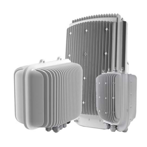
............The BreezeCOMPACT Solution 1.1.1 The BreezeCOMPACT Family Telrad’s BreezeCOMPACT family of products includes the BreezeCOMPACT , (models base stations 1000, 2000 and 3000.) For more information, please visit the BreezeCOMPACT... -
Page 18: Breezecompact Models
............1.1.2 BreezeCOMPACT Models Table 1: BreezeCOMPACT Part Numbers, Frequencies and Tx Power Tx Power Ports Platform Telrad Part Number (PN) LTE Band Frequencies per Port Rx/Tx 3400–3700 MHz Band 42 Band 42: 3400–3600... -
Page 19: Figure 2: Single Sector, Single Carrier
Chapter 1 - System DescriptionThe BreezeCOMPACT Solution The BreezeCOMPACT Solution Chapter 1: System Description ............1.1.3.1 Single Sector, Single Carrier This is the basic configuration based on a single BS that supports a single sector 4 Tx/4 Rx with bandwidth of 5, 7, 10 &... -
Page 20: Antennas
In addition to a range of standard commercial antennas, Telrad also offers a special attached antenna designed for convenient installation on top of the BreezeCOMPACT unit. For the BreezeCOMPACT unit, a special mounting kit allows installation of a standard antenna on top of the unit to minimize the space required for installation. -
Page 21: Figure 5: Gps
Chapter 1 - System DescriptionThe BreezeCOMPACT Solution The BreezeCOMPACT Solution Chapter 1: System Description ............Figure 5: GPS BreezeCOMPACT System Manual BreezeCOMPACT System Manual... -
Page 22: Telrad Overall Solution
............Telrad Overall Solution Figure 6: Telrad Solution 1.2.1 TelCore The TelCore solution is based on MC-ASN-GW for WiMAX and MC-EPC for LTE. -
Page 23: Figure 7: Mini-Centralized Asn-Gw
Chapter 1 - System DescriptionTelrad Overall Solution Telrad Overall Solution Chapter 1: System Description ............ -
Page 24: Telrad Starsuite Nms Solution
............1.2.2 Telrad StarSuite NMS Solution Telrad provides a full suite of Network Management systems, which includes: StarManager: A network management system for configuration, alarms and monitoring ... -
Page 25: Specifications
Chapter 1 - System DescriptionSpecifications Specifications Chapter 1: System Description ............Specifications 1.3.1 Modem and Radio... -
Page 26: Data Communication (Ethernet Interfaces)
Chapter 1 - System DescriptionSpecifications Specifications Chapter 1: System Description ............1.3.2 Data Communication (Ethernet Interfaces) Table 3: Data Communication (Ethernet Interfaces) -
Page 27: Environmental
Chapter 1 - System DescriptionSpecifications Specifications Chapter 1: System Description ............Table 5: Standards Compliance, General (Continued) Type Standard... -
Page 28: Antennas
Chapter 1 - System DescriptionSpecifications Specifications Chapter 1: System Description ............1.3.6.2 BreezeCOMPACT2000 Table 8: Mechanical and Electrical Specifications, BreezeCOMPACT2000 Units... - Page 29 Chapter 1 - System DescriptionSpecifications Specifications Chapter 1: System Description ............Table 10: Attached Antenna 3.3-3.8 DDS 65º...
-
Page 30: Table 11: Ant, Bs, 3.3-3.8 Ghz, Ds, Sec.65°, 16.5Dbi Minimum (P.n. 300644) Specifications
Chapter 1 - System DescriptionSpecifications Specifications Chapter 1: System Description ............1.3.7.2 3.3-3.8 GHz, 2 Ports 65º... - Page 31 Chapter 1 - System DescriptionSpecifications Specifications Chapter 1: System Description ............Table 12: ANT, BS, 3.3–3.8 GHz, DS, Sec.90°, 15.5dBi Minimum (P.N.
-
Page 32: Table 13: Ant-Ddp-65°-3.3-3.8 Ghz (P.n. 300736) Specifications
Chapter 1 - System DescriptionSpecifications Specifications Chapter 1: System Description ............1.3.7.4 3.3-3.8 GHz, 4 Ports 65º... -
Page 33: Bmax-4M-Gps Receiver Specifications
Chapter 1 - System DescriptionSpecifications Specifications Chapter 1: System Description ............Table 14: ANT-DDP-90°-3.3-3.8 GHz (P.N. - Page 34 Chapter 2: Commissioning In This Chapter: “Introduction” on page 35 “BreezeCOMPACT Installation” on page 35 “System Initial Verification” on page 36 “Configuring Parameters Required for Management Connectivity” on page 37 “Activating the Unit” on page 39...
-
Page 35: Chapter 2: Commissioning
Chapter 2 - CommissioningIntroduction Introduction Chapter 2: Commissioning ............Introduction After completing the installation process, some basic unit's parameters must be configured locally using the Monitor program in order to enable discovery by the Element Management System and remote management of the unit. -
Page 36: System Initial Verification
Chapter 2 - CommissioningSystem Initial Verification System Initial Verification Chapter 2: Commissioning ............System Initial Verification After power-up, the BTS automatically starts a self-testing procedure to verify that: ... -
Page 37: Configuring Parameters Required For Management Connectivity
Chapter 2 - CommissioningConfiguring Parameters Required for Management Connectivity Configuring Parameters Required for Management Connectivity Chapter 2: Commissioning ............Configuring Parameters Required for Management Connectivity This section describes the minimum mandatory configuration actions required to allow remote management of the site and to... -
Page 38: Configuring The L1 And L2 Parameters (If Necessary)
Chapter 2 - CommissioningConfiguring Parameters Required for Management Connectivity Configuring Parameters Required for Management Connectivity Chapter 2: Commissioning ............... -
Page 39: Applying The Configuration
Chapter 2 - CommissioningActivating the Unit Activating the Unit Chapter 2: Commissioning ............At the Manager Number prompt, enter 1 and select the Update option. -
Page 40: Creating The Bs
Chapter 2 - CommissioningActivating the Unit Activating the Unit Chapter 2: Commissioning ............Define Antenna Associations. -
Page 41: Configuring Radio Cluster Parameters
Chapter 2 - CommissioningActivating the Unit Activating the Unit Chapter 2: Commissioning ............The new BS is added to the list of BSs available in the BS node. -
Page 42: Configuring Antenna Associations
Chapter 2 - CommissioningActivating the Unit Activating the Unit Chapter 2: Commissioning ............2.5.3 Configuring Antenna Associations Using the Monitor Program... -
Page 43: Chapter 3: Operation And Administration
Chapter 3: Operation and Administration In This Chapter: “BTS System Management” on page 45 “Monitor Program” on page 46 “IP Address Configuration” on page 49 “Main Menu” on page 50 “BTS Menu” on page 51 ... -
Page 44: Bts System Management
Chapter 3 - Operation and AdministrationBTS System Management BTS System Management Chapter 3: Operation and Administration ............BTS System Management The BTS can be managed using any of the following options: ... -
Page 45: Monitor Program
Chapter 3 - Operation and AdministrationMonitor Program Monitor Program Chapter 3: Operation and Administration ............Monitor Program 3.2.1 Accessing the Monitor Program... -
Page 46: Using The Monitor Program
Chapter 3 - Operation and AdministrationMonitor Program Monitor Program Chapter 3: Operation and Administration ............3.2.2 Using the Monitor Program This section describes the Monitor program structure and navigation rules:... - Page 47 Chapter 3 - Operation and AdministrationMonitor Program Monitor Program Chapter 3: Operation and Administration ...............
-
Page 48: Ip Address Configuration
Chapter 3 - Operation and AdministrationIP Address Configuration IP Address Configuration Chapter 3: Operation and Administration ............IP Address Configuration 3.3.1 IP Address Configuration Restrictions... -
Page 49: Main Menu
Chapter 3 - Operation and AdministrationMain Menu Main Menu Chapter 3: Operation and Administration ............Main Menu The Main menu of the Monitor program includes the following options: 1 –... -
Page 50: Bts Menu
Chapter 3 - Operation and AdministrationBTS Menu BTS Menu Chapter 3: Operation and Administration ............BTS Menu The BTS menu includes the following options: ... -
Page 51: Connectivity
Chapter 3 - Operation and AdministrationBTS Menu BTS Menu Chapter 3: Operation and Administration ............3.5.1.4 Contact Person An optional descriptive parameter. - Page 52 Chapter 3 - Operation and AdministrationBTS Menu BTS Menu Chapter 3: Operation and Administration ............The unit supports the following IP connectivity modes: ...
- Page 53 Chapter 3 - Operation and AdministrationBTS Menu BTS Menu Chapter 3: Operation and Administration ...............
- Page 54 Chapter 3 - Operation and AdministrationBTS Menu BTS Menu Chapter 3: Operation and Administration ............3.5.2.2.5 Sector 2 –...
- Page 55 Chapter 3 - Operation and AdministrationBTS Menu BTS Menu Chapter 3: Operation and Administration ............In Unified Connectivity Mode, the External Management VLAN ID should be configured to the same value as the Bearer VLAN ID.
- Page 56 Chapter 3 - Operation and AdministrationBTS Menu BTS Menu Chapter 3: Operation and Administration ............CAUTION If you want to switch from Data Port 1 to Data Port 2 (or vice versa), the unit must be reset (or powered down and then powered up) after physically connecting to the new port.
- Page 57 Chapter 3 - Operation and AdministrationBTS Menu BTS Menu Chapter 3: Operation and Administration ............For Data Port 1, if the Operational State is Up, the Duplex Mode is forced to Full Duplex.
-
Page 58: Unit Control
Chapter 3 - Operation and AdministrationBTS Menu BTS Menu Chapter 3: Operation and Administration ............3.5.2.5.2 DSCP The DSCP value of management traffic. - Page 59 Chapter 3 - Operation and AdministrationBTS Menu BTS Menu Chapter 3: Operation and Administration ............Each software version includes two identifiers: ...
- Page 60 Chapter 3 - Operation and AdministrationBTS Menu BTS Menu Chapter 3: Operation and Administration ............3.5.3.2.6 Load boot and RCW This option is used to perform an update when the existing BreezeCOMPACT software is upgraded from R4.1 to R5.0.
- Page 61 Chapter 3 - Operation and AdministrationBTS Menu BTS Menu Chapter 3: Operation and Administration ............The Files Control menu includes the following menu options: ...
-
Page 62: Management
Chapter 3 - Operation and AdministrationBTS Menu BTS Menu Chapter 3: Operation and Administration ............The default TFTP Target IP Address is 192.168.1.1 (the same as the default for the External Management IP Address). - Page 63 Chapter 3 - Operation and AdministrationBTS Menu BTS Menu Chapter 3: Operation and Administration ............3.5.4.1.1.4 Enable Traps Distribution Indicates whether the sending of traps to the management station is enabled or disabled.
- Page 64 Chapter 3 - Operation and AdministrationBTS Menu BTS Menu Chapter 3: Operation and Administration ............3.5.4.2.1.2 Community Read Only The SNMP Read Community to be used by the Authorized Manager.
-
Page 65: Sector Menu
Chapter 3 - Operation and AdministrationSector Menu Sector Menu Chapter 3: Operation and Administration ............Sector Menu In the current release, the unit supports a single sector. - Page 66 Chapter 3 - Operation and AdministrationSector Menu Sector Menu Chapter 3: Operation and Administration ............3.6.2.1 Bandwidth The bandwidth of the Radio Cluster, in MHz.
-
Page 67: Bs Menu
Chapter 3 - Operation and AdministrationBS Menu BS Menu Chapter 3: Operation and Administration ............BS Menu In the current release, a Single and Dual BS is supported. - Page 68 Chapter 3 - Operation and AdministrationBS Menu BS Menu Chapter 3: Operation and Administration ............3.7.1.4 Name An optional descriptive parameter.
-
Page 69: Select
Chapter 3 - Operation and AdministrationBS Menu BS Menu Chapter 3: Operation and Administration ............3.7.2 Select Select the BS to view or update its parameters or to delete it. - Page 70 Chapter 3 - Operation and AdministrationBS Menu BS Menu Chapter 3: Operation and Administration ............3.7.2.1.2 Operator ID The unique identifier of the wireless network operator.
- Page 71 Chapter 3 - Operation and AdministrationBS Menu BS Menu Chapter 3: Operation and Administration ............3.7.2.2 Air Frame Structure The Air Frame Structure menu includes the following options:...
- Page 72 Chapter 3 - Operation and AdministrationBS Menu BS Menu Chapter 3: Operation and Administration ............The valid range is from 0 to 69.
- Page 73 Chapter 3 - Operation and AdministrationBS Menu BS Menu Chapter 3: Operation and Administration ...............
-
Page 74: Table 17: First Zone Minimum Size Recommended Value Range
Chapter 3 - Operation and AdministrationBS Menu BS Menu Chapter 3: Operation and Administration ............The available options are 2, 4,..34 (2xN, where N=1-17) or -1 for No Limitation. -
Page 75: Table 18: Calculating The Upper Limit Value (Y) For Minimum And Maximum Size
Chapter 3 - Operation and AdministrationBS Menu BS Menu Chapter 3: Operation and Administration ............Where A=46 for BW of 5 or 10 MHz, and 32 for BW of 7 MHz. - Page 76 Chapter 3 - Operation and AdministrationBS Menu BS Menu Chapter 3: Operation and Administration ...............
-
Page 77: Table 19: Dl:ul Ratios
Chapter 3 - Operation and AdministrationBS Menu BS Menu Chapter 3: Operation and Administration ............The table below describes the DL:UL ratio as a function of BS Bandwidth and Total Uplink Duration. - Page 78 Chapter 3 - Operation and AdministrationBS Menu BS Menu Chapter 3: Operation and Administration ............3.7.2.4.1 Target Ni The target noise and interference level for the PUSC zone, in dBm.
-
Page 79: Table 20: Functionality Of Allowed Ducting Mitigation Modes, 5/10 Mhz Bs Bandwidth
Chapter 3 - Operation and AdministrationBS Menu BS Menu Chapter 3: Operation and Administration ............3.7.2.5.4 Ducting Mitigation Mode Sudden changes in the atmosphere's moisture and temperature profiles can on random occasions make radio signals... -
Page 80: Table 21: Functionality Of Allowed Ducting Mitigation Modes, 7 Mhz Bs Bandwidth
Chapter 3 - Operation and AdministrationBS Menu BS Menu Chapter 3: Operation and Administration ............Table 20: Functionality of Allowed Ducting Mitigation Modes, 5/10 MHz BS Bandwidth (Continued) Configured Mitigation... - Page 81 Chapter 3 - Operation and AdministrationBS Menu BS Menu Chapter 3: Operation and Administration ...............
- Page 82 Chapter 3 - Operation and AdministrationBS Menu BS Menu Chapter 3: Operation and Administration ............A change in the 802.1p Priority takes effect after the next reset.
- Page 83 Chapter 3 - Operation and AdministrationBS Menu BS Menu Chapter 3: Operation and Administration ............3.7.2.6.3.3.4 Service Flow Data Delivery Type The Service Flow Type for data delivery services: ugs, rtvr, nrtvr, be, ertvr or any.
- Page 84 Chapter 3 - Operation and AdministrationBS Menu BS Menu Chapter 3: Operation and Administration ............3.7.2.6.4.1 Pools Availability The Pools Availability option enables you to view/update the status (Enabled/Disabled) of each of the pools.
- Page 85 Chapter 3 - Operation and AdministrationBS Menu BS Menu Chapter 3: Operation and Administration ............3.7.2.8 Scheduler Scheduling uncommitted (above the maximum reserved rate) traffic can be done using one of the following options:...
- Page 86 Chapter 3 - Operation and AdministrationBS Menu BS Menu Chapter 3: Operation and Administration ............A change in the Scheduler Mode takes effect after the next reset.
-
Page 87: Chassis Menu
Chapter 3 - Operation and AdministrationChassis Menu Chassis Menu Chapter 3: Operation and Administration ............Chassis Menu The Chassis menu includes the following options: ... -
Page 88: Ports Control
Chapter 3 - Operation and AdministrationChassis Menu Chassis Menu Chapter 3: Operation and Administration ............3.8.1.2 Maximal Frame Size The maximal size (excluding the preamble) of frames on the Ethernet port. -
Page 89: Gps Menu
Chapter 3 - Operation and AdministrationGPS Menu GPS Menu Chapter 3: Operation and Administration ............GPS Menu The GPS menu includes the following options: ... -
Page 90: Figure 10: Gps Chaining Mode Connectivity
Chapter 3 - Operation and AdministrationGPS Menu GPS Menu Chapter 3: Operation and Administration ............3.9.1.5 UTC Time and Date The UTC (Coordinated Universal Time) date and time. - Page 91 Chapter 3 - Operation and AdministrationGPS Menu GPS Menu Chapter 3: Operation and Administration ............3.9.1.8 Stop TX After Hold Over Timeout This parameter applies only when the External 1 PPS is enabled.
-
Page 92: Inventory & Statuses
Chapter 3 - Operation and AdministrationGPS Menu GPS Menu Chapter 3: Operation and Administration ............3.9.1.14 Stop Date When Daylight Saving is enabled, this parameter defines the date for ending the daylight-savings feature (Advance Hour... - Page 93 Chapter 3 - Operation and AdministrationGPS Menu GPS Menu Chapter 3: Operation and Administration ............3.9.2.8 Hold Over timeout passed This parameter indicates whether the Hold Over Timeout has passed (applies only after entering Hold Over state).
-
Page 94: Rh Menu
Chapter 3 - Operation and AdministrationRH Menu RH Menu Chapter 3: Operation and Administration ............3.10 RH Menu The RH (Radio Head) menu includes the following options:... -
Page 95: Spectrum Analyzer
Chapter 3 - Operation and AdministrationSpectrum Analyzer Spectrum Analyzer Chapter 3: Operation and Administration ............Calculated Tx Power equals the Radio Cluster’s Tx Power. -
Page 96: Show Current State
Chapter 3 - Operation and AdministrationSpectrum Analyzer Spectrum Analyzer Chapter 3: Operation and Administration ............8 –... -
Page 97: Show Results
Chapter 3 - Operation and AdministrationSpectrum Analyzer Spectrum Analyzer Chapter 3: Operation and Administration ............3.11.6 Show Results This parameter shows the sort method to be used for displaying results. -
Page 98: Dual Carrier Load Balancing
Chapter 3 - Operation and AdministrationDual Carrier Load Balancing Dual Carrier Load Balancing Chapter 3: Operation and Administration ............3.12 Dual Carrier Load Balancing BreezeCOMPACT’s Dual Carrier topology in a Single Sector enables load balancing between two... - Page 99 ............We’re on your wavelength.
Need help?
Do you have a question about the BreezeCOMPACT 1000 and is the answer not in the manual?
Questions and answers