
Subscribe to Our Youtube Channel
Related Manuals for Mitsubishi A953GOT-SBD-M3-H


Summary of Contents for Mitsubishi A953GOT-SBD-M3-H
- Page 1 HARDWARE MANUAL A953 HANDY GOT TARGET MODELS (FOR RS-232C CONNECTION) A953GOT-LBD-M3-H A953GOT-SBD-M3-H...
- Page 2 • If in doubt about the operation or use of GOT-A900 please consult the nearest Mitsubishi Electric distributor. • This manual is subject to change without notice.
- Page 3 A953 HANDY GOT A953 HANDY GOT HARDWARE MANUAL Manual number : JY992D99801 Manual revision : C Date : September 2008...
- Page 4 A953 HANDY GOT...
- Page 5 A953 HANDY GOT FAX BACK Mitsubishi has a world wide reputation for its efforts in continually developing and pushing back the frontiers of industrial automation. What is sometimes overlooked by the user is the care and attention to detail that is taken with the documentation. However, to continue this process of improvement, the comments of the Mitsubishi users are always welcomed.
- Page 6 A953 HANDY GOT...
- Page 7 A953 HANDY GOT Guidelines for the Safety of the User and Protection of the A953 HANDY GOT This manual provides information for the use of the A953 HANDY GOT. The manual has been written to be used by trained and competent personnel. The definition of such a person or persons is as follows;...
-
Page 8: Abbreviations
A953 HANDY GOT • Under no circumstances will Mitsubishi Electric be liable responsible for any consequential damage that may arise as a result of the installation or use of this equipment. • All examples and diagrams shown in this manual are intended only as an aid to understanding the text, not to guarantee operation. - Page 9 A953 HANDY GOT Abbreviation/ Description generic name/term FA controller Generic name of LM610, LM7600 and LM8000 Generic name of C200HS, C200H, C200HX, C200HG, C200HE, CQM1, PLC by Omron C1000H, C2000H and CV1000 Generic name of GL60S, GL60H, GL70H, GL120, GL130, CP-9200SH, PLC by Yaskawa Electric CP-9300MS, MP-920 and MP-930 PLC by Allen-Bradley...
-
Page 10: Introduction
Explanation on specifications, installation, wiring and switches A manual of the used Handy GOT is required. • A953 HANDY GOT HARDWARE MANUAL Describes the specifications, wiring, installation, etc. of the A953GOT-SBD-M3-H/A953GOT- LBD-M3-H. Manual No.: JY992D99801 Explanation on the display unit Separate manual (Ask the sales agency from which you have purchased the Handy GOT.) -
Page 11: Registration
A953 HANDY GOT Screen creation software • GT Works2/GT Designer2 OPERATING MANUAL (STARTUP) Describes how to install the GT Works2/GT Designer2 to a personal computer and how to refer to the online manual. • GT Designer2 (SW D5C-GTD2-E) REFERENCE MANUAL -separate manual- Describes how to install and start up the screen creation software (GT Designer2). -
Page 12: Wiring Procedure
A953 HANDY GOT Wiring procedure The work procedures from starting up to making ready the Handy GOT using this manual are explained below. Outline Reference page 1.2 Product configuration Introduces the model name expression of the Handy GOT and accessories. 1.3 Introduction of cables and screen creation software (options) and their applications Introduces optional products (cables and connector conversion box) and explains their easy... - Page 13 A953 HANDY GOT Wiring Reference page 2.2.5 Wiring of power supply 2-11 Explains connection of an external cable and the DC power supply. 3.2 Wiring of operation switches Explains how to wire four operation switches and control the LED indication. 3.3 Wiring of emergency stop switch Explains the wiring of the emergency stop switch and the cautions.
- Page 14 A953 HANDY GOT MEMO...
-
Page 15: Table Of Contents
A953 HANDY GOT A953 HANDY GOT Contents Table of Contents Guideline of Safty.................v Abbreviations ...................... vi Associated Manuals...................viii Registration......................ix Wiring procedure ....................x 1. Introduction....................1-1 1.1 Outline of product ....................1-1 1.2 Product configuration................... 1-3 1.2.1 Handy GOT ....................... 1-3 1.3 Introduction of cables and screen creation software (options) and their applications...................... - Page 16 A953 HANDY GOT Contents 3. Wiring and Handling of Switches............3-1 3.1 Outline of switches ....................3-2 3.2 Wiring of operation switches................3-5 3.2.1 Inputs of operation switches ..................3-5 3.2.2 Lighting of operation indicator LEDs ................. 3-6 3.3 Wiring of emergency stop switch ................. 3-8 3.4 Setting of grip switch ...................
- Page 17 A953 HANDY GOT Contents 8. Connection to PLC by Omron ...............8-1 8.1 System configuration ................... 8-1 8.1.1 System configuration when C200H/C200HS/C200Ha Series PLC is connected ..8-1 8.1.2 System configuration when CQM1 is connected............8-2 8.1.3 System configuration when C1000H/C2000H is connected........8-2 8.1.4 System configuration when CV1000 is connected ............
- Page 18 A953 HANDY GOT Contents 13.Connection to PLC by Siemens ............13-1 13.1 System configuration ..................13-1 13.2 Initial setting....................... 13-2 13.3 Connection cable ....................13-3 14.Diagnostics..................14-1 14.1 When POWER LED does not light ..............14-1 14.2 When an operation switch or emergency stop switch does not operate.... 14-2 14.3 When LC screen is dark ..................
-
Page 19: Introduction
A953 HANDY GOT A953 HANDY GOT Introduction Installation Wiring Wiring and Handling of Switches Specifications Connection to Peripheral Equipment CPU Direct Connection Computer Link Connection Connection to PLC by Omron Connection to PLC by Yaskawa Electric Connection to PLC by Allen-Bradley Connection to PLC by Sharp Connection to Microcomputer Connection to PLC by Siemens... -
Page 20: Connection To Plc By Siemens
A953 HANDY GOT Introduction Installation Wiring Wiring and Handling of Switches Specifications Connection to Peripheral Equipment CPU Direct Connection Computer Link Connection Connection to PLC by Omron Connection to PLC by Yaskawa Electric Connection to PLC by Allen-Bradley Connection to PLC by Sharp Connection to Microcomputer Connection to PLC by Siemens Diagnostics... -
Page 21: Outline Of Product
A953 HANDY GOT Introduction 1 Introduction This section describes the product configuration and the system configuration of the A95 handy graphic operation terminal (abbreviated as "Handy GOT" in the text). Outline of product The Handy GOT is used as an operation terminal connected to a controller such as the MELSEC FX/QnA/Q Series PLC and a PLC manufactured by another company. - Page 22 A953 HANDY GOT Introduction 1 Display unit: The display unit is an LCD with touch switches equivalent to that of the graphic operation terminal A950GOT. The operator can easily monitor the ON/OFF status of bit devices of the PLC, set such bit devices to ON or OFF, monitor the set value and the present value of word devices of the PLC, and change such values of word devices.
-
Page 23: Product Configuration
A953 HANDY GOT Introduction 1 Product configuration The model name of the Handy GOT is expressed as follows. A95 GOT- BD-M3-H 1) 3: RS-232C communication type 2) S: STN type eight-color liquid crystal L: STN type black-and-white liquid crystal 1.2.1 Handy GOT The handy graphic operation terminal consists of the following components. -
Page 24: Introduction Of Cables And Screen Creation Software (Options) And Their Applications
A953 HANDY GOT Introduction 1 Introduction of cables and screen creation software (options) and their applications Order the following options in accordance with the connected PLC configuration. 1.3.1 Common options 1) Screen creation software For the details of versions applicable in the Handy GOT and the software working environment, refer to 1.5. -
Page 25: Part Identification
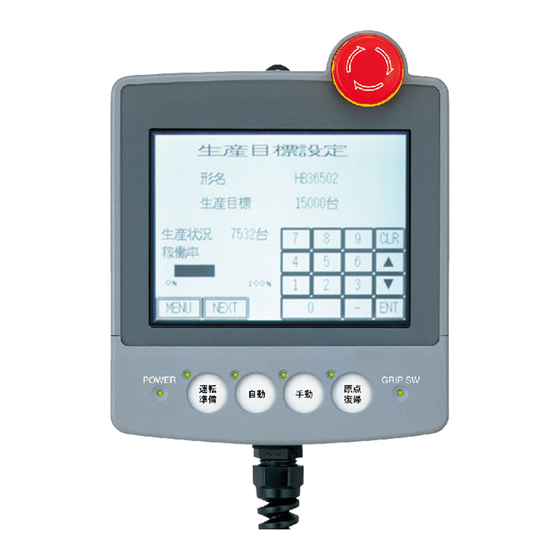
Lit while 24V DC power is supplied to the Handy GOT. 2) LC display unit with touch switches Offers 8 colors in the A953GOT-SBD-M3-H or 2 colors (black and white) in the A953GOT- LBD-M3-H. This display unit offers the functions equivalent to those offered by the display unit of the graphic operation terminal A950GOT. -
Page 26: Rear Panel
A953 HANDY GOT Introduction 1 1.4.2 Rear panel The name and function of each part of the rear panel of the Handy GOT are described below. When the rear cover is removed, diversified connectors can be seen. W h e n t h e r e a r c o v e r i s r e m o v e d ( e n l a r g e d v i e w ) 3 ) ' 3 ) ' N o t u s e d... -
Page 27: Applicable Versions Of Os And Screen Creation Software
A953 HANDY GOT Introduction 1 Applicable versions of OS and screen creation software When using the Handy GOT, make sure to prepare the OS and the screen creation software of the version shown below. 1.5.1 Applicable OS versions Handy GOT Applicable BIOS OS version A95 GOT-SBD-M3-H... - Page 28 A953 HANDY GOT Introduction 1 MEMO...
-
Page 29: Installation Wiring
A953 HANDY GOT Installation Wiring 2 Installation Wiring This section describes installation of the Handy GOT and wiring of the power supply and the operation switches. Thoroughly understand the specifications before performing installation and wiring. Installation method Cautions on installation •... -
Page 30: Holding
A953 HANDY GOT Installation Wiring 2 Cautions on wiring • The Handy GOT has the DC power specifications. Connect the DC power cable to the dedicated terminals described in this manual. If the AC power is supplied to the power supply, operation switches or emergency stop switches, the Handy GOT may be burnt. -
Page 31: Hanging On Wall
A953 HANDY GOT Installation Wiring 2 2.1.2 Hanging on wall When operating the Handy GOT while keeping it hung on the wall, use the metal fixture for wall hanging provided on the rear face of the Handy GOT. M e t a l h o o k f o r m o u n t i n g o n w a l l f 5 m m ( 0 . -
Page 32: Wiring
A953 HANDY GOT Installation Wiring 2 Wiring Cautions on wiring • Make sure to shut down all phases of the power supply outside the Handy GOT before starting the installation or wiring work. If any phase is not shut down, you may get electrical shock or the Handy GOT may be damaged. -
Page 33: Outline Of Connection
A953 HANDY GOT Installation Wiring 2 2.2.1 Outline of connection When attaching and detaching the Handy GOT or directly wiring the Handy GOT, perform connection in either of the following methods. When attaching/detaching the Handy GOT (using only an external cable) Handy GOT External cable PLC connection cable... -
Page 34: Cable Selection
A953 HANDY GOT Installation Wiring 2 2.2.2 Cable selection The figure below shows the outline of connection to the PLC. For the details, refer to section 2.2.3. To Q Series PLC To the power supply and operation switches To PLC Connect a cable to To power supply the connector inside... -
Page 35: Pin Arrangement And Signal Names Of Cables And Connectors
A953 HANDY GOT Installation Wiring 2 2.2.3 Pin arrangement and signal names of cables and connectors 1) External cable F9GT-HCAB -3M The figure and the table below show the pin arrangement of untied wires and connectors of external cables F9GT-HCAB-3M and F9GT-HCAB1-3M. F9GT-HCAB-3M F9GT-HCAB1-3M 25-pin D-Sub, male connector... -
Page 36: Connection Of External Cable
A953 HANDY GOT Installation Wiring 2 2.2.4 Connection of external cable This section explains how to connect an optional external cable and the Handy GOT. 1) Remove the rear cover. Rear face of Handy GOT a) Loosen four mounting screws, and open the rear cover. Note: Remove only the mounting screws. - Page 37 A953 HANDY GOT Installation Wiring 2 b) Tighten the hexagon nut for mounting of the external cable to the Handy GOT. Make sure to tighten the hexagon nut for P a c k i n g mounting with a sufficient force to avoid H e x a g o n n u t f o r m o u n t i n g looseness.
-
Page 38: Wiring Of Power Supply
A953 HANDY GOT Installation Wiring 2 2.2.5 Wiring of power supply To the Handy GOT, the power is supplied from the PLC or an external power supply unit. The current consumption of the Handy GOT is 400mA/24V DC. Example when the power is supplied from an external power supply Connect a 24V DC external power supply unit to the power supply line (pin) of the external cable (untied or with a connector) of the Handy GOT. -
Page 39: Panel Face Processing
A953 HANDY GOT Installation Wiring 2 Panel face processing This section explains how to process the panel face when the Handy GOT is attached and detached through a connector. 2.3.1 A953 Handy GOT 1) Attaching the connector on the panel face a) External cable (with 25-pin D-Sub, male connector) F9GT-HCAB-3M (3m, 9' 10") b) Relay cable for PLC connection... -
Page 40: Appearance Of Relay Cables
A953 HANDY GOT Installation Wiring 2 2.3.2 Appearance of relay cables The panel cut size is as shown in section 2.3.3. Appearance of the relay cable F9GT-HCAB5-150 (dedicated to the Q Series PLC) 1 . 5 m ( 4 ' 1 1 " ) T o p o w e r s u p p l y a n d o p e r a t i o n s w i t c h e s C o n n e c t e d A n a m e l a b e l i s a t t a c h e d t o t h e t i p o f... -
Page 41: Panel Cut Size For Relay Cable
A953 HANDY GOT Installation Wiring 2 2.3.3 Panel cut size for relay cable When attaching the connector of a relay cable on the panel face so that the Handy GOT can be attached and detached, process the panel face as shown below. 47.04 (1.85") 2-φ3.2±0.1 (0.13"... - Page 42 A953 HANDY GOT Installation Wiring 2 MEMO 2-14...
-
Page 43: Wiring And Handling Of Switches
A953 HANDY GOT Wiring and Handling of Switches 3 Wiring and Handling of Switches This chapter explains wiring and handling of the operation switches and the grip switch as well as control of the LEDs for confirming the switch pressing status. Cautions on installation •... -
Page 44: Outline Of Switches
A953 HANDY GOT Wiring and Handling of Switches 3 Outline of switches The Handy GOT is equipped with the following switches and indicator LEDs. 1) Switch assignment The figure below shows assignment of the switches. Each switch is abbreviated as shown in the table below. - Page 45 A953 HANDY GOT Wiring and Handling of Switches 3 2) Switch internal wiring Connection of each switch is as shown below inside the Handy GOT. Display circuit Power RS-232C (for PC) DC24V supply LCD panel Power DC24G circuit Touch switch circuit Grip RS-232C switch...
- Page 46 A953 HANDY GOT Wiring and Handling of Switches 3 3) Connection diagram of external cables and connected equipment Handy GOT Connected internal wiring equipment 25pin D-Sub Untied cable (PLC) SW-COM Fresh green Sky blue Inputs Black/white Red/white Green/white Wire them for Brown/white emergency stop...
-
Page 47: Wiring Of Operation Switches
A953 HANDY GOT Wiring and Handling of Switches 3 Wiring of operation switches The operation switches are assigned as shown below, and connected to the PLC through an external cable. Connection example H a n d y G O T S w i t c h S W 1 S W 2... -
Page 48: Lighting Of Operation Indicator Leds
A953 HANDY GOT Wiring and Handling of Switches 3 3.2.2 Lighting of operation indicator LEDs Each of the four operation switches SW1 to SW4 is equipped with a green LED which indicates the pressing status of the switch. Each LED is assigned to the bit 0 to the bit 3 of a word device. When the bit value is "1", the corresponding LED is lit. - Page 49 A953 HANDY GOT Wiring and Handling of Switches 3 - GT Designer (SW D5C-GOTR-PACKE) a) Select "Common"-"System Information" to open the "System Information Setting" dialog box. b) Set "Read Device" (System Signal 1). c) Click the "External I/O Function Output Information" check box to give a check mark.
-
Page 50: Wiring Of Emergency Stop Switch
A953 HANDY GOT Wiring and Handling of Switches 3 Wiring of emergency stop switch The emergency stop switch is assigned as shown below, and connected to the PLC through an external cable. Connection example Handy GOT Handy GOT As control signal to turn on/off the power of the external equipment. -
Page 51: Setting Of Grip Switch
A953 HANDY GOT Wiring and Handling of Switches 3 Setting of grip switch The grip switch is provided on the side of the Handy GOT. While the grip switch (a-contact) is pressed and held, manipulation of the touch switches on the screen is effective. The ON/OFF status of the grip switch can be monitored in the PLC. -
Page 52: Grip Switch Operation Timing
A953 HANDY GOT Wiring and Handling of Switches 3 3.4.2 Grip switch operation timing 1) Effective screens When the grip switch is set effective, manipulate touch switches while pressing and holding the grip switch. However, on the setup screen, the self-diagnosis screen and the screen & OS copy screen, touch switches are always enabled without regard to effectiveness of the grip switch. - Page 53 A953 HANDY GOT Wiring and Handling of Switches 3 When "If it is released" is set to "NO ACTION" While the grip switch is in the ON status, a touch switch turns ON when pressed, and turns OFF when released or when the grip switch is released (set to OFF). Grip switch Indicator LED for grip switch...
-
Page 54: Communication With Plc
A953 HANDY GOT Wiring and Handling of Switches 3 3.4.3 Communication with PLC In the PLC, the ON/OFF status of the grip switch can be confirmed using the bit device set as follows. In the Handy GOT, the green GRIP SW LED provided on the front face lights when the grip switch is pressed. - Page 55 A953 HANDY GOT Wiring and Handling of Switches 3 - GT Designer (SW D5C-GOTR-PACKE) a) Select "Common"-"System Information" to open the "System Information Setting" dialog box. b) Set "Write Device" (System Signal 2). c) Click the "OK" button to close the "System Information"...
-
Page 56: Creation Of Operation Switch Name Sheet
A953 HANDY GOT Wiring and Handling of Switches 3 Creation of operation switch name sheet This section describes how to create the operation switch name sheet. 3.5.1 Creation of name sheet 1) Prepare a mount sheet and an OHP sheet (transparent sheet) offered as accessories. 2) Write arbitrary switch names on the name sheet mount. -
Page 57: Attachment Of Sheet
A953 HANDY GOT Wiring and Handling of Switches 3 3.5.2 Attachment of sheet 1) Removing the operation switch cover O p e r a t i o n s w i t c h Inser t a screwdriver into the clearance *1 or *3 c o v e r between the operation switch cover and the main body, and push up slowly the operation switch cover... - Page 58 A953 HANDY GOT Wiring and Handling of Switches 3 MEMO 3-16...
-
Page 59: Specifications
• Do not disassemble or modify the Handy GOT. Disassembly or modification may cause failure, malfunction or fire. • For replacement or repair of the backlight, consult with a Mitsubishi Electric distributor. • Turn OFF the power before connecting or disconnecting a cable. -
Page 60: General Specifications
A953 HANDY GOT Specifications 4 General specifications 4.1.1 Outside dimensions The figure below shows the outside dimensions of the Handy GOT. φ5(0.2") 63.5(2.5") 15(0.6") φ10(0.4") 21(0.83") 13(0.52") 78(3.08") (1.5") (0.83") 5(0.2") POWER GRIP 38(1.5") 38(1.5") 156(6.15") 65.5(2.58") 65.5(2.58") 13(0.52") 156(6.15") a: 25(0.99") 35(1.38") φ25(0.99") -
Page 61: Power Unit Specifications
A953 HANDY GOT Specifications 4 4.1.2 Power unit specifications The table below shows the specifications of the power unit of the Handy GOT. Power unit specifications Specifications Item Handy GOT +10% Supply voltage 24V DC -15% Power ripple 200mV or less Fuse 1.0A (built in) Current consumption... - Page 62 A953 HANDY GOT Specifications 4 • Performance specifications Item A953GOT-LBD-M3-H A953GOT-SBD-M3-H Operation switch 4 points, a-contact 10mA/24V DC (for input to PLC) Operation life: 1,000,000 times 1 points, b-contact 1A/24V DC, independent wiring Emergency stop switch (AH165-VR01 manufactured by Fuji Electric Co., Ltd.)
-
Page 63: Plc Cpu Which Can Be Monitored
A953 HANDY GOT Specifications 4 PLC CPU which can be monitored Whether or not a PLC CPU can be monitored in the Handy GOT is determined by the system (connection form) up to the monitored PLC CPU. 4.2.1 In case of A953 Handy GOT The table below shows the PLC CPU of each connection form which can be monitored. -
Page 64: Devices Names Which Can Be Monitored
A953 HANDY GOT Specifications 4 Devices names which can be monitored 1) In the case of QCPU (A mode) and ACPU Device name Available set monitor range Input (X) X0~X1FFF Output (Y) Y0~Y1FFF Internal relay (M) M0~M8191 Annunciator (F) F0~F2047 Link relay (B) B0~B1FFF Special internal relay (M) - Page 65 A953 HANDY GOT Specifications 4 2) In the case of QCPU (Q mode) and QnACPU Device name Available set monitor range Input (X) X0~X1FFF Output (Y) Y0~Y1FFF Internal relay (M) M0~M32767 Latch relay (L) L0~L32767 Annunciator (F) F0~F32767 Link relay (B) B0~B7FFF Special internal relay (M) M9000~M9255...
- Page 66 A953 HANDY GOT Specifications 4 3) In the case of MELSEC-FXCPU Device name Available set monitor range Device number expression Input (X) X0000~X0377 Octal Output (Y) Y0000~Y0377 Auxiliary relay (M) M0000~M3071 State (S) S0000~S0999 Special auxiliary relay (M) M8000~M8255 Decimal devices Timer contact (T) T000~T255...
- Page 67 A953 HANDY GOT Specifications 4 4) In the case of PLC by Omron Device name Available set monitor range I/O relay ..0000~51115 Internal auxiliary relay Data link relay (LR) LR0000~LR6315 Auxiliary memory relay (AR) AR0000~AR2715 Holding relay (HR) HR0000~HR9915 TIM000~TIM511 Timer contact (TIM) devices CNT000~CNT511...
- Page 68 A953 HANDY GOT Specifications 4 b) When the CP-9200SH, the MP-920 or the MP-930 is used Device name Available set monitor range Coil MB0~MB4095F Input relay IB0000~IBFFFF devices GOT bit register GB64~GB1023 Input register IW0~IW7FFF Word Holding register MW0~MW32767 devices GOT data register GD64~GD1023 c) When the CP-9300MS is used...
- Page 69 A953 HANDY GOT Specifications 4 6) In the case of PLC by Allen-Bradley Device name Available set monitor range Device number expression B0030000~B003255F Bit (B) B0100000~B255255F TT0040000~TT0042550 Timer (timing bit) (TT) TT0100000~TT2552550 TN0040000~TN0042550 Timer (timing bit) (TN) TN0100000~TN2552550 CU0050000~CU0052550 Counter (up-counter) (CU) CU0100000~CU2552550 Decimal devices...
- Page 70 A953 HANDY GOT Specifications 4 7) In the case of PLC by Sharp Device name Available set monitor range Device number expression 0~15777 I/O relay 20000~75777 Timer/counter (contact) T/C0000~T/C1777 T/C0000~T/C1777 Timer/counter (present value) (b0000~b3776) 09000~09776 19000~19776 29000~29776 39000~39776 49000~49776 59000~59776 69000~69776 79000~79776 89000~89776...
- Page 71 A953 HANDY GOT Specifications 4 9) In the case of PLC by Toshiba Device name Available set monitor range External input (X) X0000~X511F External output (Y) Y0000~Y511F Internal relay (R) R0000~R999F Special relay (S) S0000~S255F Link register relay (Z) Z0000~Z999F Link relay (L) L0000~L255F devices...
- Page 72 A953 HANDY GOT Specifications 4 MEMO 4-14...
-
Page 73: Connection To Peripheral Equipment
A953 HANDY GOT Connection to Peripheral Equipment 5 Connection to Peripheral Equipment This section explains connection of the Handy GOT to the peripheral equipment. Connection to peripheral equipment for Handy GOT The figure below shows connection to the peripheral equipment for the Handy GOT. •... -
Page 74: Connection Diagram
A953 HANDY GOT Connection to Peripheral Equipment 5 Connection diagram 1) Transfer cable FX-232CAB-1 9-pin Personal 9-pin D-Sub, computer GOT side D-Sub, female side female 2) Transfer cable F -232CAB-1 25-pin Personal 9-pin D-Sub, computer GOT side D-Sub, male side female 3) Transfer cable AC30R2-9SS 9-pin... -
Page 75: Cpu Direct Connection
A953 HANDY GOT CPU Direct Connection 6 CPU Direct Connection System configuration 6.1.1 Connection to QCPU Handy GOT External cable dedicated to handy GOT F9GT-HCAB- M QCPU Relay cable for PLC connection To PLC For power supply and operation switches F9GT-HCAB5-150... -
Page 76: Connection To Fxcpu
A953 HANDY GOT CPU Direct Connection 6 6.1.2 Connection to FXCPU 1) When the FX Series PLC is connected Execute communication through RS-232C with the FX Series PLC. For communication, the following option (function extension board or special adapter for RS-232C communication) is required. -
Page 77: Connection Cable
A953 HANDY GOT CPU Direct Connection 6 Connection cable The user should prepare the RS-232C cable which connects the GOT and the PLC CPU (CPU direct connection). The connection diagram, the connector, etc. of RS-232C cables are shown below. 1) Connection diagram a) When the QCPU is connected F9GT-HCAB5-150 GOT side (F9GT-HCAB -3M) - Page 78 A953 HANDY GOT CPU Direct Connection 6 b) When the port of the connected FX -232-BD, FX -232-BD or FX -232ADP is the 9-pin D-Sub type FXCPU side (9- GOT side (F9GT-HCAB -3M) pin D-Sub, male, = none or 1) #4-40UNC inch- Cable connection and signal direction thread type)
- Page 79 A953 HANDY GOT CPU Direct Connection 6 2) Used connectors and connector covers - Connector on the side of the cable dedicated to the GOT The connector of the cable dedicated to the GOT (F9GT-HCAB- M) has the following model name. Use a counterpart connector compatible with this connector. 17JE-23250-02 (D8A2) 25-pin D-Sub, male connector manufactured by DDK Ltd.
- Page 80 A953 HANDY GOT CPU Direct Connection 6 MEMO...
-
Page 81: Computer Link Connection
A953 HANDY GOT Computer Link Connection 7 Computer Link Connection Computer link connection (RS-232C communication) has the following features. • Because a computer link unit and the GOT can be connected on the one-to-one basis, two or more GOT units can be connected in accordance with the number of computer link units connected to the PLC CPU. -
Page 82: Initial Setting
A953 HANDY GOT Computer Link Connection 7 Initial setting 7.2.1 Setting in communication link unit and serial communication unit When connecting the GOT to a computer link unit or serial communication unit for monitoring, set the switches of the computer link unit or the serial communication unit as shown below. 1) When the QJ71C24(-R2) is connected Set the switches of the QJ71C24(-R2) using the I/O assignment setting of the GPPW. - Page 83 A953 HANDY GOT Computer Link Connection 7 2) When the AJ71QC24(-R2) is connected J71QC24 CH1.ERR. CPUR/W CH2.ERR. CH.1 CH.2 SD.WAIT SD.WAIT •~10 •~1 STATION Mode selector switch MODE (for CH1) Transmission When the When the specifications setting transmission speed transmission speed switches (for CH1) is set to 38400 bps is set to 19,200 bps...
- Page 84 A953 HANDY GOT Computer Link Connection 7 4) When the AJ71UC24 is connected J71UC24 2 - C / N 2 - SD 2 - P / S 2 - RD 2 - PRO 2 - SIO 2 - NEU 4 - C / N 2 - ACK 4 - P / S 2 - NAK...
- Page 85 MELSEC A1S CPU24-R2 STOP STOP L CLR L CLR RESET RESET RESET RESET ERROR ERROR MITSUBISHI MITSUBISHI Mode selector switch Transmission specifications setting ← switches PULL When the cover is open 7) When the A2CCPUC24 is connected Mode selector switch Station No.
-
Page 86: Setting In Got
A953 HANDY GOT Computer Link Connection 7 7.2.2 Setting in GOT When the GOT is connected to the computer link unit or the serial communication unit for monitoring, setting is not required on the GOT side in principle. However, when the AJ71QC24N(-R2) or the A1SJ71QC24N(-R2) is connected and data transmission at 38,400 bps is required, the transmission speed on the GOT side should be set to 38,400 bps. -
Page 87: Connection Cable
A953 HANDY GOT Computer Link Connection 7 Connection cable The user is to prepare the RS-232C cable which connects the GOT and the PLC CPU (serial communication unit, computer link unit or PLC CPU having the computer link function). The connection diagrams, connectors, etc. of the RS-232C cables are shown below. 1) Connection diagram a) When the connector on the PLC CPU side is the 9-pin D-Sub type (QJ71C24(-R2), A1SJ71QC24(-R2), A1SJ71UC24-R2, A1SJ71C24-R2, A1SCPUC24-R2... - Page 88 A953 HANDY GOT Computer Link Connection 7 b) When the port on the PLC CPU side is the 25-pin D-Sub type (AJ71QC24(-R2) or AJ71UC24) GOT side (F9GT-HCAB -3M) PLC CPU side = none or 1) Cable connection and signal direction Signal Untied Signal...
-
Page 89: Connection To Plc By Omron
A953 HANDY GOT Connection to PLC by Omron 8 Connection to PLC by Omron System configuration 8.1.1 System configuration when C200H/C200HS/C200Hα Series PLC is connected Communication board PLC by Omron C200HW-COM02, C200HW-COM05, C200Hα Series C200HW-COM06 Base mounting type upper PLC by Omron link unit Handy GOT C200H-LK201-V1... -
Page 90: System Configuration When Cqm1 Is Connected
A953 HANDY GOT Connection to PLC by Omron 8 8.1.2 System configuration when CQM1 is connected Handy GOT External cable dedicated to PLC by Omron handy GOT For untied cable F9GT-HCAB- M/ CQM1 F9GT-HCAB1- M *1 The connection cable is to be prepared by the user. For the details of the cable preparation method, refer to section 8.3. -
Page 91: System Configuration When Cv1000 Is Connected
A953 HANDY GOT Connection to PLC by Omron 8 8.1.4 System configuration when CV1000 is connected Handy GOT PLC by Omron External cable dedicated to handy GOT For untied cable F9GT-HCAB- M/ CV1000 F9GT-HCAB1- M *1 The connection cable is to be prepared by the user. For the details of the cable preparation method, refer to section 8.3. -
Page 92: Initial Setting
A953 HANDY GOT Connection to PLC by Omron 8 Initial setting 8.2.1 Setting of switches in upper link unit When using the upper link unit (C200H-LK201-V1 or C500H-LK201-V1), set the switches as shown below. 1) When the C200H-LK201-V1 is used Setting of switches on the front face a) Setting of the SW1 and the SW2... - Page 93 A953 HANDY GOT Connection to PLC by Omron 8 2) When the C500H-LK201-V1 is used Setting of switches on the front face a) Setting of upper link/local Set "upper link". Operating b) Setting of the RS-232C/RS-422 selector switch For RS-422 communication, set "RS-422" Reciving (upper side).
-
Page 94: Setting In Cv1000
A953 HANDY GOT Connection to PLC by Omron 8 8.2.2 Setting in CV1000 1) Setting of switches In the CPU (CV1000), set the switches shown below. Setting of switches on the front face ‚Ì a) Setting of the RS-232C/RS-422 selector switch For RS-422 communication, set "RS-422"... -
Page 95: Initialization Of Cqm1
A953 HANDY GOT Connection to PLC by Omron 8 8.2.3 Initialization of CQM1 When using the RS-232C port of the CQM1, write numeric values to the devices shown below, and initialize the RS-232C port of the CQM1 using a peripheral tool or the DM monitor. For the details, refer to the CQM1 INSTRUCTION MANUAL. -
Page 96: Connection Cable
A953 HANDY GOT Connection to PLC by Omron 8 Connection cable The connection diagram and the connector of RS-232C cables which connect the upper link unit, the communication board, the CPU (CV1000 or CQM1) and the GOT are shown below. 1) Connection diagram a) Upper link unit Omron PLC side... - Page 97 A953 HANDY GOT Connection to PLC by Omron 8 c) CPU (CV1000 or CQM1) Omron PLC side GOT side (F9GT-HCAB -3M) (9-pin D-Sub, = none or 1) male, milli-thread Cable connection and signal direction type) Signal Untied Signal name wire color number number name...
- Page 98 A953 HANDY GOT Connection to PLC by Omron 8 MEMO 8-10...
-
Page 99: Connection To Plc By Yaskawa Electric
A953 HANDY GOT Connection to PLC by Yaskawa Electric 9 Connection to PLC by Yaskawa Electric System configuration Memo bus unit PLC by Yaskawa Electric JAMSC-IF60/61 GL60S,GL60H,GL70H PLC by Yaskawa Electric Memo bus unit Handy GOT 120 CPU 341 00 GL120,GL130 PLC by Yaskawa Electric External cable dedicated to... -
Page 100: Initial Setting
A953 HANDY GOT Connection to PLC by Yaskawa Electric 9 Initial setting 1) Setting in the PLC by Yaskawa Electric When connecting the GOT to the PLC by Yaskawa Electric, set the communication and the port shown below using a peripheral tool. For the details of the setting method, refer to the INSTRUCTION MANUAL of the PLC by Yaskawa Electric. -
Page 101: Connection Cable
A953 HANDY GOT Connection to PLC by Yaskawa Electric 9 Connection cable 9.3.1 RS-232C cable 1) Connection diagram a) When the GL60S, the GL60H, the GL70H, the GL120, the GL130, the MP-920, the MP- 930, the CP-9200(H) or the PROGGIC-8 (when 9-pin D-Sub port is used) is used Yaskawa Electric PLC side GOT side (F9GT-HCAB -3M) - Page 102 A953 HANDY GOT Connection to PLC by Yaskawa Electric 9 c) When the CP-9300MS is used Yaskawa Electric PLC GOT side side (F9GT-HCAB -3M) (9-pin D-Sub, male, = none or 1) milli-thread type) Cable connection and signal direction Signal Untied Signal name wire...
- Page 103 A953 HANDY GOT Connection to PLC by Yaskawa Electric 9 3) Caution on cable preparation The maximum cable length varies depending on the specifications of the used PLC by Yaskawa Electric. For the details, refer to the INSTRUCTION MANUAL of the PLC by Yaskawa Electric.
- Page 104 A953 HANDY GOT Connection to PLC by Yaskawa Electric 9 MEMO...
-
Page 105: Connection To Plc By Allen-Bradley
A953 HANDY GOT Connection to PLC by Allen-Bradley 10 Connection to PLC by Allen-Bradley 10.1 System configuration Handy GOT External cable dedicated to PLC by Allen-Bradley handy GOT For untied cable F9GT-HCAB- M/ SLC 5/03,SLC 5/04 F9GT-HCAB1- M *1 The connection cable is to be prepared by the user. For the details of the cable preparation method, refer to section 10.4. -
Page 106: Transmission Specifications
A953 HANDY GOT Connection to PLC by Allen-Bradley 10 10.3 Transmission specifications The table below shows the transmission specifications for communication between the GOT and the PLC by Allen-Bradley. Item Contents of setting Transmission speed 19200 bps Data length 8 bits Stop bit 1 bit Parity bit... - Page 107 A953 HANDY GOT Connection to PLC by Allen-Bradley 10 3) Caution on cable preparation The maximum cable length varies depending on the specifications of the used PLC by Allen-Bradley. For the details, refer to the INSTRUCTION MANUAL of the PLC by Allen- Bradley.
- Page 108 A953 HANDY GOT Connection to PLC by Allen-Bradley 10 MEMO 10-4...
-
Page 109: Connection To Plc By Sharp
A953 HANDY GOT Connection to PLC by Sharp 11 Connection to PLC by Sharp 11.1 System configuration PLC by Sharp Handy GOT JW-22CU,JW-70CUH, JW-100CUH External cable dedicated to PLC by Sharp handy GOT For untied cable F9GT-HCAB- M/ JW-32CUH,JW-33CUH F9GT-HCAB1- M *1 The connection cable is to be prepared by the user. -
Page 110: Initial Setting
A953 HANDY GOT Connection to PLC by Sharp 11 11.2 Initial setting 11.2.1 When GOT is directly connected to PLC CPU When connecting the GOT directly to the PLC CPU, the communication setting is required at first for the communication port. Using a peripheral tool, set as shown below to the system memory in the PLC CPU. -
Page 111: When Link Unit Is Connected
A953 HANDY GOT Connection to PLC by Sharp 11 2) When the JW-32CUH or the JW-33CUH is used System memory Setting item Contents of setting address Set the transmission speed, the parity and the stop bit using bits D0 to D5 as shown below. D6 D5 D4 D3 D2 D1 D0 −... -
Page 112: Transmission Specifications
A953 HANDY GOT Connection to PLC by Sharp 11 11.3 Transmission specifications The table below shows the transmission specifications for communication between the GOT and the PLC by Sharp. 1) JW-22CU, JW-70CUH or JW-100CUH (in direct connection to the PLC CPU) Item Contents of setting Transmission speed... -
Page 113: Connection Cable
A953 HANDY GOT Connection to PLC by Sharp 11 11.4 Connection cable The connection diagram and the connector of RS-232C cables which connect the PLC CPU and the GOT are shown below. 1) Connection diagram a) PLC CPU (JW-22CU, JW-70CUH or JW-100CUH) Sharp PLC side GOT side (F9GT-HCAB -3M) (15-pin D-Sub,... - Page 114 A953 HANDY GOT Connection to PLC by Sharp 11 2) Used connectors and connector covers - Connector on the side of the cable dedicated to the GOT The connector of the cable dedicated to the GOT (F9GT-HCAB- M) has the following model name.
-
Page 115: Connection To Microcomputer
A953 HANDY GOT Connection to Microcomputer 12 Connection to Microcomputer The personal computer, the microcomputer board, the PLC, etc. (hereafter referred to as "host") can monitor virtual devices (D) in the GOT through data send/receive. Device data area Internal memory Write/read command RW 0100 000A 0163 0362 D100... -
Page 116: Transmission Specifications
A953 HANDY GOT Connection to Microcomputer 12 12.2 Transmission specifications The table below shows the transmission specifications for communication between the GOT and the host. Item Contents of setting Data bit 7 bits Parity bit Provided (even) Stop bit 1 bit Sum check Provided Transmission speed... - Page 117 A953 HANDY GOT Connection to Microcomputer 12 3) Caution on cable preparation Make sure that the maximum cable length does not exceed the value shown in the table below. Connection destination Maximum cable Remarks PLC CPU length (m) Total of F9GT-HCAB-3M and cable prepared by user Microcomputer Total of F9GT-HCAB1-3M and cable prepared by user When F9GT-HCAB1-10M is cut...
-
Page 118: When Dtr Is Not Used
A953 HANDY GOT Connection to Microcomputer 12 12.3.2 When DTR is not used 1) Connection diagram GOT side (F9GT-HCAB -3M) Host = none or 1) Cable connection and signal direction Signal Untied Signal name wire color number number name CD(DCD) Blue RD(RXD) SD(TXD) -
Page 119: Device Data Area
A953 HANDY GOT Connection to Microcomputer 12 12.4 Device data area The table below shows the data area of virtual devices in the GOT. Description Address (decimal) D0~D2 Not used Communication error status The contents vary depending on the error status of the communication driver of the GOT. -
Page 120: Communication Command
A953 HANDY GOT Connection to Microcomputer 12 Description Address (decimal) Interrupt output When data is written, the contents of the lower 8 bits are output as the interrupt code. D14~D19 Not used D20~D2031 User area D2032~D2034 Not used 1-sec binary counter D2035 The counter counts up at every second after the power is turned on. -
Page 121: Data Transfer Format
A953 HANDY GOT Connection to Microcomputer 12 12.5.2 Data transfer format There are two types of data transfer formats executed by commands. The table below shows each data transfer format. The data transfer format can be changed over using the utility function in the GOT. For the details of the utility function, refer to the GOT-A900 SERIES OPERATING MANUAL (EXTENSION FUNCTION/OPTIONAL FUNCTION FOR SW D5C-GOTR-PACKE). -
Page 122: Caution On Use
A953 HANDY GOT Connection to Microcomputer 12 12.5.3 Caution on use The sum check code indicates the numeric value of the lower 1 byte (8 bits) of the result (sum) obtained when the data in the sum check range is added as the binary data. Example: When the RD command is executed for the addresses D100 and D101 Number Address... -
Page 123: Batch Read Command (Rd)
A953 HANDY GOT Connection to Microcomputer 12 12.5.4 Batch read command (RD) The contents of the batch read command are shown below. 12 bytes 1 byte 1 byte 2 bytes 4 bytes 2 bytes 2 bytes Number Address of points check Error (02H) -
Page 124: Batch Write Command (Wd)
A953 HANDY GOT Connection to Microcomputer 12 12.5.5 Batch write command (WD) The contents of the batch write command are shown below. 268 bytes maximum 1 byte 1 byte 4 × (1 to 64) bytes 2 bytes 4 bytes 2 bytes 2 bytes Number Address... -
Page 125: Random Read Command (Rr)
A953 HANDY GOT Connection to Microcomputer 12 12.5.6 Random read command (RR) The contents of the random read command are shown below. 262 bytes maximum 1 byte 1 byte 4 × (1 to 64) bytes 2 bytes 2 bytes Address 1 Address 2 Address n . -
Page 126: Random Write Command (Rw)
A953 HANDY GOT Connection to Microcomputer 12 12.5.7 Random write command (RW) The contents of the random write command are shown below. 518 bytes maximum 1 byte 1 byte 8 × (1 to 64) bytes 2 bytes 2 bytes Address 1 Data 1 Address 2 Data 2... -
Page 127: Connection To Plc By Siemens
A953 HANDY GOT Connection to PLC by Siemens 13 Connection to PLC by Siemens 13.1 System configuration HMI adapter (by Siemens) PLC by Siemens SIMATIC S7-300 Series MLFB:6ES7 972-0CA11-0XA0 SIMATIC S7-400 Series Handy GOT PLC by Siemens (several units connected with Profibus) Profibus External cable dedicated to handy GOT... -
Page 128: Initial Setting
A953 HANDY GOT Connection to PLC by Siemens 13 13.2 Initial setting When connecting the GOT to the PLC by Siemens, set the contents shown below using "Setup" of the utility function of the GOT. • Baud rate Set the transmission speed between the GOT and the PLC by Siemens. (At shipment, it is set to "19200".) •... -
Page 129: Connection Cable
A953 HANDY GOT Connection to PLC by Siemens 13 13.3 Connection cable The connection diagram and the connector of RS-232C cables which connect the HMI adapter and the GOT are shown below. 1) Connection diagram HMI adapter side GOT side (F9GT-HCAB -3M) (9-pin D-Sub, = none or 1) male, milli-thread... - Page 130 A953 HANDY GOT Connection to PLC by Siemens 13 MEMO 13-4...
-
Page 131: Diagnostics
• Do not disassemble or modify the Handy GOT. Disassembly or modification may cause failure, malfunction or fire. • For replacement or repair of the backlight, consult with a Mitsubishi Electric distributor. • Turn OFF the power before connecting or disconnecting a cable. -
Page 132: When An Operation Switch Or Emergency Stop Switch Does Not Operate
If the conductivity is not given, wire breakage or poor contact is present in the external cable or relay cable, or the circuits inside the Handy GOT may be damaged. If it is suspected that the circuits inside the Handy GOT are damaged, consult with a Mitsubishi Electric distributor. Signals whose conductivity is checked Switch... -
Page 133: When Lc Screen Is Dark
If the screen remains dark even after adjustment, it is recommended to replace the backlight. For replacement of the backlight, consult with a Mitsubishi Electric distributor. For the details of the utility function, refer to the GOT-A900 SERIES OPERATING MANUAL (EXTENTION FUNCTIONS/OPTIONAL FUNCTIONS). - Page 134 A953 HANDY GOT Diagnostics 14 MEMO 14-4...
-
Page 135: A-1: System Configuration Example In Microcomputer Connection
A953 HANDY GOT Appendix A: A-1: System Configuration Example in Microcomputer Connection A system configuration example in microcomputer connection is shown below. Refer to it in constructing a system in microcomputer connection. A-1-1: System configuration The figure below shows a system example using the A975GOT adopted in this system configuration. - Page 136 A953 HANDY GOT b) Monitor screen image Base screen 1 (A)Numeric display function Sample Screen 1 This function monitors and displays the device value of the D21. Only while "Sample Screen 1" is displayed, the device value is incremented. (B)Touch switch 1 Screen 2 This switch changes over the screen to "Sample Screen 2"...
-
Page 137: A-1-3: Sample Program In Host
A953 HANDY GOT A-1-3: Sample program in host Sample programs (C language) in the host are stored in the SW D5C-GOTR-PACKE. By selecting a sample program for microcomputer connection as an option while installing the software package, the sample program is available. For the operating procedure (about how to select the option) during installation, refer to the SW D5C-GOTR-PACKE(V)OPERATING MANUAL. - Page 138 A953 HANDY GOT *1 The table below shows the send packet structure of the batch write packet for changeover to screen 1. Number Item Address Data of points check Stored value 0x02 0x57 0x44 0x30 0x30 0x32 0x30 0x30 0x31 0x30 0x30 0x30 0x31 0x03 0x38 0x32 −...
- Page 139 A953 HANDY GOT A953 HANDY GOT Introduction Installation Wiring Wiring and Handling of Switches Specifications Connection to Peripheral Equipment CPU Direct Connection Computer Link Connection Connection to PLC by Omron Connection to PLC by Yaskawa Electric Connection to PLC by Allen-Bradley Connection to PLC by Sharp Connection to Microcomputer Connection to PLC by Siemens...
- Page 140 A953 HANDY GOT Introduction Installation Wiring Wiring and Handling of Switches Specifications Connection to Peripheral Equipment CPU Direct Connection Computer Link Connection Connection to PLC by Omron Connection to PLC by Yaskawa Electric Connection to PLC by Allen-Bradley Connection to PLC by Sharp Connection to Microcomputer Connection to PLC by Siemens Diagnostics...
- Page 142 HARDWARE MANUAL A953 HANDY GOT HEAD OFFICE: TOKYO BUILDING, 2-7-3 MARUNOUCHI, CHIYODA-KU, TOKYO 100-8310 JAPAN HIMEJI WORKS: 840, CHIYODA CHO, HIMEJI, JAPAN A953H-HW-E MODEL 09R812 MODEL CODE JY992D99801C Effective Sep. 2008 (MEE) Specification are subject to change without notice.
Need help?
Do you have a question about the A953GOT-SBD-M3-H and is the answer not in the manual?
Questions and answers