Table of Contents
Advertisement
Advertisement
Table of Contents
Troubleshooting

Related Manuals for Mitsubishi GOT1000 GT11


Summary of Contents for Mitsubishi GOT1000 GT11
-
Page 3: Safety Precautions
SAFETY PRECAUTIONS (Always read these precautions before using this equipment.) Before using this product, please read this manual and the relevant manuals introduced in this manual carefully and pay full attention to safety to handle the product correctly. The precautions given in this manual are concerned with this product. In this manual, the safety precautions are ranked as "DANGER"... - Page 4 [DESIGN PRECAUTIONS] DANGER Incorrect operation of the touch switch(s) may lead to a serious accident if the GOT backlight is gone out. When the GOT backlight goes out, the POWER LED flickers (green/orange) and the display section turns black and causes the monitor screen to appear blank, while the input of the touch switch(s) remains active.
- Page 5 [MOUNTING PRECAUTIONS] CAUTION Use the GOT in the environment that satisfies the general specifications described in this manual. Not doing so can cause an electric shock, fire, malfunction or product damage or deterioration. When mounting the GOT to the control panel, tighten the mounting screws in the specified torque range.
- Page 6 [WIRING PRECAUTIONS] CAUTION Plug the communication cable into the connector of the connected unit and tighten the mounting and terminal screws in the specified torque range. Undertightening can cause a short circuit or malfunction. Overtightening can cause a short circuit or malfunction due to the damage of the screws or unit. Insert the bus cables for QnA, ACPU, and motion controller (A series) into the GOT's bus interface connectors until they click into the place.
- Page 7 [STARTUP/MAINTENANCE PRECAUTIONS] CAUTION Do not disassemble or modify the unit. Doing so can cause a failure, malfunction, injury or fire. Do not touch the conductive and electronic parts of the unit directly. Doing so can cause a unit malfunction or failure. The cables connected to the unit must be run in ducts or clamped.
-
Page 8: Revisions
This manual confers no industrial property rights or any rights of any other kind, nor does it confer any patent licenses. Mitsubishi Electric Corporation cannot be held responsible for any problems involving industrial property rights which may occur as a result of using the contents noted in this manual. -
Page 9: Introduction
• Since the example indicated by this manual, technical bulletin, the catalog, etc. is reference, please use it after confirming the function and safety of equipment and system when employing. Mitsubishi Electric will accept no responsibility for actual use of the product based on these illustrative examples. -
Page 10: Table Of Contents
CONTENTS SAFETY PRECAUTIONS....................A-1 REVISIONS ........................A-6 INTRODUCTION ......................A-7 OUTLINE PRECAUTIONS ..................... A-7 CONTENTS........................A-8 ABOUT MANUALS....................... A-14 ABBREVIATIONS AND GENERIC TERMS ..............A-15 HOW TO READ THIS MANUAL................... A-18 1. OVERVIEW..............1-1 1.1 Features ........................1-4 1.2 Rough Pre-operation Procedure.................1-5 2. - Page 11 6. INSTALLATION.............. 6-1 6.1 Control Panel Inside Dimensions for Mounting GOT ..........6-2 6.2 Panel Cutting Dimensions ..................6-4 6.3 Mounting Position....................... 6-4 6.4 Control Panel Temperature and Mounting Angle ............6-5 6.5 Installation Procedure ....................6-6 7. WIRING................7-1 7.1 Power Supply Wiring....................
- Page 12 9.3.3 Basic operation of settings change ....................9-9 10. COMMUNICATION INTERFACE SETTING (COMMUNICATION SETTING)........10-1 10.1 Communication Setting ..................10-1 10.1.1 Communication setting functions ....................10-1 10.1.2 Communication setting display operation ...................10-1 10.1.3 Description of communication setting screen ................10-2 10.1.4 Operation of communication setting ...................10-6 10.2 Communication Detail Settings ................10-9 10.2.1 Communication detail settings functions..................10-9 10.2.2 Communication detail settings display operation................10-9...
- Page 13 13.1.2 Data type and storage location ....................13-1 13.1.3 OS version confirmation......................13-3 13.1.4 Display file........................... 13-5 13.2 OS Information ....................... 13-6 13.2.1 Function of OS information ......................13-6 13.2.2 Display operation of OS information screen ................13-7 13.2.3 Display example of OS information .................... 13-8 13.2.4 Operation of OS information .......................
- Page 14 14.6.2 Display operation of touch panel check ..................14-15 14.6.3 Touch panel check operations ....................14-16 14.7 I/O Check......................14-17 14.7.1 I/O check function ........................14-17 14.7.2 Display operation of I/O check ....................14-17 14.7.3 I/O check operation........................14-18 14.8 System Alarm Display ..................14-20 14.8.1 System alarm display function ....................14-20 14.8.2 Displaying the system alarm display..................14-20 14.8.3 Operating the system alarm display..................14-21 14.9 GOT Start Time ....................14-22...
- Page 15 18.3.3 Specific example of troubleshooting ................... 18-9 18.4 Troubleshooting for Monitoring ................18-10 18.5 Starting GOT ......................18-11 18.5.1 Power-Off..........................18-11 18.5.2 Communication from GT Designer2 to the GOT............... 18-11 APPENDICES..............App-1 Appendix 1 External Dimensions ................App- 1 Appendix 2 Usage Condition of Utility Function............App- 8 Appendix 3 Transportation Precautions..............App- 14 Appendix 3.1 Relevant models.....................
-
Page 16: About Manuals
ABOUT MANUALS The following manuals are also related to this product. In necessary, order them by quoting the details in the tables below. For the handy GOT (GT1155HS-QSBD, GT1150HS-QLBD), refer to the Handy GOT User’s Manual provided separately. Related Manuals Manual Number Manual Name (Model Code) -
Page 17: Abbreviations And Generic Terms
ABBREVIATIONS AND GENERIC TERMS Abbreviations and generic terms used in this manual are as follows: Abbreviations and generic terms Description GT SoftGOT1000 Abbreviation of GT SoftGOT1000 GT1595 GT1595-X Abbreviation of GT1595-XTBA, GT1595-XTBD GT1585V-S Abbreviation of GT1585V-STBA GT1585 GT1585-S Abbreviation of GT1585-STBA, GT1585-STBD GT1575V-S Abbreviation of GT1575V-STBA GT1575-S... - Page 18 Option unit Abbreviations and generic terms Description Printer unit GT15-PRN Video input unit GT15V-75V4 RGB input unit GT15V-75R1 Video/RGB unit Video/RGB input unit GT15V-75V4R1 RGB output unit GT15V-75ROUT CF card unit GT15-CFCD GT15-CFEX-C08SET CF card extension unit External I/O unit GT15-DIO Sound output unit GT15-SOUT...
- Page 19 Abbreviations and generic terms Description Abbreviation of SW D5C-LLT-E(-EV) type ladder logic test tool function software packages GX Simulator (SW5D5C-LLT (-EV) or later versions) Document Converter Abbreviation of document data conversion software Document Converter for GOT1000 series PX Developer Abbreviation of SW D5C-FBDQ-E type FBD software package for process control License key (for GT SoftGOT1000) Abbreviations and generic terms Description...
-
Page 20: How To Read This Manual
HOW TO READ THIS MANUAL Functions This manual describes functions available for the GT Designer2 Version 2.58L. For the added functions by the product version upgrade, refer to the list of functions added by GT Designer2 version upgrade in Appendices. Symbols Following symbols are used in this manual. -
Page 21: Overview
1. OVERVIEW About GOT A GOT is installed on the panel surface of a control panel or operating panel and connects to the PLC within the control panel. The GOT carries out switch operation, lamp display, data display, message display, etc. Connector for program For the display screen, two kinds of screens are available : user screen... - Page 22 About Manual The following manuals related to GOT 1000 series are available. Refer to each manual in accordance with the intended use. (1) Installation of the software programs Drawing Data transfer For operations from creating project data to transferring data to GOT, refer to the following manuals.
- Page 23 (2) Installing a GOT connection to a PLC For the operations from installing a GOT to communicating with a PLC CPU, refer to the following manuals. (Included) GT15 General Description GT15 User's Manual GOT1000 Series Purpose GT 11 General GT11 User's Manual Connection Manual Description Confirming part names and...
-
Page 24: Features
1.1 Features (1) Improved monitoring performance and connectivity to FA devices • Multiple languages are displayed using the Unicode2.1-compatible fonts and beautiful characters are drawn using the TrueType and high quality fonts. • Two types of display modes are provided: 256-color display and monochrome display. In the monochrome display, 16 scales are used to improve the display. -
Page 25: Rough Pre-Operation Procedure
1.2 Rough Pre-operation Procedure The outline procedure before operating GOT is shown. Start Refer to GT Designer2 Version Install GT Designer2 in the PC. Basic Operation/Data Transfer Manual. Refer to GT Designer2 Version Create project data. Screen Design Manual or Help functions of GT Designer2. -
Page 26: System Configuration
GOT1000 Series Connection Manual Option function board Protective sheet CF card Stand GRAPHIC OPERATION TERMINAL 1000 Personal computer Bar code reader MITSUBISHI Commercially available Commercially available Memory card CF card Memory card adaptor • GT11 does not connect a printer. 2 - 1... -
Page 27: Component List
2.2 Component List (1) Explanation of the GOT model name G T 1 1 5 5 2 : Built-in RS-232 Communication Q : Built-in Q bus interface A : Built-in A bus Blank : Built-in RS-422 Power type A : 100 to 240VAC D : 24VDC L : 5VDC Panel color type... -
Page 28: Got (Gt11)
2.2.1 GOT (GT11) Models with a built-in serial interface 5.7" [320 x 240 dots], STN color liquid crystal, 256 colors, 24VDC, memory size 3MB, built- GT1155-QSBD in battery, built-in serial interface 5.7" [320 x 240 dots], STN monochrome liquid crystal, monochrome (black/white), 16 GT1150-QLBD scales, 24VDC, memory size 3MB, built-in battery, built-in serial interface Models with a built-in bus interface... -
Page 29: Option (Optional Components For Gt11)
2.2.2 Option (Optional components for GT11) PLC connection cable (Sold separately) Product name Model name Cable length Contents GT01-C10R4-8P FXCPU direct GT01-C30R4-8P connection For connecting FXCPU (MINI DIN 8 pins) and cable GOT. GT01-C100R4-8P For connecting FXCPU expansion board (MINI expansion DIN 8 pins) and GOT. - Page 30 Bus cable for connection to QCPU (Q mode) (Sold separately) Product name Model name Description GT15-QC06B Cable length 0.6m GT15-QC12B Cable length 1.2m Q add-on cable For connecting QCPU and GOT Inter-GOT connection GT15-QC30B Cable length 3m For interconnecting GOTs cable GT15-QC50B Cable length 5m...
- Page 31 Product name Model name Description GT15-C07BS Cable length 0.7m GT15-C12BS Cable length 1.2m GT15-C30BS Cable length 3m Long inter-GOT GT15-C50BS Cable length 5m For interconnecting GOTs connection cable GT15-C100BS Cable length 10m GT15-C200BS Cable length 20m GT15-C300BS Cable length 30m A0J2HCPU For connecting the power supply unit (A0J2- GT15-J2C10B...
- Page 32 Connection cables for JTEKT PLCs (Sold separately) Product Model name Description name GT09-C30R41201-6C Cable length 3 m RS-422 GT09-C100R41201-6C Cable length 10 m For connecting GOT to JTEKT PLC cable GT09-C200R41201-6C Cable length 20 m GT09-C300R41201-6C Cable length 30 m RS-232 GT09-C30R21201-25P Cable length 3 m...
- Page 33 Connection cables for HITACHI PLCs (Sold separately) Product Model name Description name GT09-C30R40401-7T Cable length 3m GT09-C100R40401-7T Cable length 10m RS-422 For connecting GOT to HITACHI intelligent serial port module cable GT09-C200R40401-7T Cable length 20m GT09-C300R40401-7T Cable length 30m For connecting GOT to HITACHI PLC, intelligent serial port GT09-C30R21101-6P Cable length 3m RS-232...
-
Page 34: Index
For the operation-checked models, refer to "List of valid devices applicable for GOT1000 series" (T10-0039) separately available. The Technical News above is available as a reference at the information site for Mitsubishi industrial automation products MELFANSweb home page. (MELFANSweb website: http://wwwf2.mitsubishielectric.co.jp/english/index.html) - Page 35 Option function board (Sold separately) Product name Model name Contents Option function board GT11-50FNB Option function board Necessity of mounting the option function board may offer depending on the hardware version. Refer to the following for detailes. Section 8.3 Option Function Board Stand (Sold separately) Product name Model name...
- Page 36 For the operation-checked models, refer to "List of valid devices applicable for GOT1000 series" separately available (T10-0039). The Technical News above is available as a reference at the Information site for Mitsubishi industrial automation products MELFANSweb home page. (MELFANSweb home page: http://wwwf2.mitsubishielectric.co.jp/melfansweb/english/index_e.htm) 2 - 11 2.2 Component List...
-
Page 37: Specifications
3. SPECIFICATIONS 3.1 General Specifications Item Specifications Display Operating 0 to 50 section ambient Other than temperature 0 to 55 (when horizontally installed), 0 to 50 (when vertically installed) display section Storage ambient temperature -20 to 60 10 to 90% RH, non-condensing Operating ambient humidity 10 to 90% RH, non-condensing Storage ambient humidity... -
Page 38: Performance Specifications
3.2 Performance Specifications • GT1155-QSBD, GT1150-QLBD Specifications Item GT1155-QSBD GT1150-QLBD Type STN color liquid crystal STN monochrome (white/black) liquid crystal Screen size 5.7" Resolution 240 dots Display size W115(4.53) H86(3.39)[mm](inch) (Horizontal format) 16-dot standard font: 20 characters 15 lines, 12-dot standard font: 26 characters 20 lines Display character (Horizontal format) - Page 39 • GT1155-QTBDQ, GT1155-QSBDQ, GT1150-QLBDQ, GT1155-QTBDA, GT1155-QSBDA, GT1150-QLBDA Specifications Item GT1155-QTBDQ GT1155-QSBDQ GT1150-QLBDQ GT1155-QTBDA GT1155-QSBDA GT1150-QLBDA STN monochrome (black/ Type TFT color liquid crystal Color liquid crystal white) liquid crystal Screen size 5.7" Resolution 240 dots Display size W115(4.53) H86 (3.39)[mm](inch) (Horizontal format) 16-dot standard font: 20 characters 15 lines, 12-dot standard font: 26 characters Display character...
- Page 40 Specifications Item GT1155-QTBDQ GT1155-QSBDQ GT1150-QLBDQ GT1155-QTBDA GT1155-QSBDA GT1150-QLBDA W167(6.58) H135(5.32) D56(2.21)[mm](inch)(Excluding USB environmental External dimensions protective cover) (Horizontal format) Panel cutting dimensions W153 (6.03) H121(4.77)[mm] (inch)(Horizontal format) Weight 0.9kg(Excluding mounting fixtures) Compatible software package GT Designer2 Version2 or later Bright dots (always lit) and dark dots (unlit) may appear on a liquid crystal display panel. It is impossible to completely avoid this symptom, as the liquid crystal display comprises of a great number of display elements.Flickers may be observed depending on the display color.Please note that these dots appear due to its characteristic and are not caused by product defect.
-
Page 41: Built-In Interface Specifications
3.3 Built-in Interface Specifications • GT1155-QSBD, GT1150-QLBD Specifications Item GT1155-QSBD GT1150-QLBD Serial interface, RS422-compliant, 1ch Transmission speed :115,200/57,600/38,400/19,200/9,600/4,800bps RS-422 Connecter type : D-sub 9-pin (female) : PLC communication Serial interface, RS232-compliant, 1ch Transmission speed : 115,200/57,600/38,400/19,200/9,600/4,800bps Connecter type : D-sub 9-pin (male) RS-232 : PLC communication, barcode reader connection, PC Built-in... -
Page 42: Power Supply Specifications
3.4 Power Supply Specifications • GT1155-QSBD, GT1150-QLBD Specifications Item GT1155-QSBD GT1150-QLBD Input power supply voltage 24VDC (+10% -15%), ripple voltage 200mV or less Fuse (built-in, not 1.0A exchangeable) Power consumption 9.84W (410mA/24VDC) or less 9.36W (390mA/24VDC) or less At backlight off 4.32W (180mA/24VDC) or less Inrush current 15A or less (26.4V) 2ms... - Page 43 • GT1155-QTBDQ, GT1155-QSBDQ, GT1150-QLBDQ, GT1155-QTBDA, GT1155-QSBDA, GT1150-QLBDA Specifications Item GT1155-QTBDQ GT1155-QSBDQ GT1150-QLBDQ GT1155-QTBDA GT1155-QSBDA GT1150-QLBDA Input power supply voltage DC24V(+10% -15%)ripple voltage 200mV or less Fuse (built-in, 1.0A irreplaceable) 9.84W (410mA/24VDC) or 9.84W (410mA/24VDC) or 9.84W (410mA/24VDC) or Power consumption less less less...
-
Page 44: Part Name
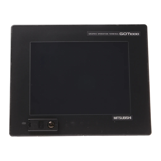
4. PART NAME 4.1 Front Panel GRAPHIC OPERATION TERMINAL 1000 1) 2) MITSUBISHI 3) 4) Name Specifications Display screen Displays the utility screen and the user creation screen. Touch key For operating the touch switches in the utility screen and the user creation screen... -
Page 45: Back Panel
4.2 Back Panel Remark Connecting the back panel For the connection to the controller (PLC, microcomputer board, bar code reader, etc) or PC, refer to the following. GOT 1000 Series Connection Manual GT1155-QSBD, GT1150-QLBD 1) 2) Battery cover opened CF CARD ACCESS OFF ON CF CARD... - Page 46 GT1155-QTBDQ, GT1155-QSBDQ, GT1150-QLBDQ, GT1155-QTBDA, GT1155-QSBDA, GT1150-QLBDA Battery cover opened Power supply terminal layout CF card cover opened Name Specifications Compatible GOT : GT1155-QTBDQ, GT1155-QSBDQ, GT1150-QLBDQ : For connection to QCPU (Q mode)/motion controller CPU (Q series) 1) Bus interface Compatible GOT : GT1155-QTBDA, GT1155-QSBDA, GT1150-QLBDA : For connection to QnA/ACPU/motion controller CPU (A series) For communicating with controller (bar code) or personal computer (OS...
-
Page 47: Emc Directive
5. EMC DIRECTIVE For the products sold in European countries, the conformance to the EMC Directive, which is one of the European Directives, has been a legal obligation since 1996. Also, conformance to the Low Voltage Directive, another European Directives, has been a legal obligation since 1997. Manufacturers who recognize their products must conform to the EMC and Low Voltage Directives required to declare that their products conform to these Directives and put a "CE mark"... -
Page 48: Control Cabinet
5.1.2 Control cabinet The GOT is an open type device (device installed to another device) and must be installed in a conductive control panel or cabinet. It not only assure the safety but also has a large effect to shut down the noise generated from GOT, on the control panel. -
Page 49: Grounding
Pollution level 3: An environment where conductive dust exits and conductivity may be generated due to the accumulated dust. An environment for a typical factory floor. Pollution level 4: Continuous conductivity may occur due to rain, snow, etc. An outdoor environment. 5.1.3 Grounding It is necessary to use the GOT grounding terminal only when it is in the grounded condition. -
Page 50: System Configuration When Emc Directive Is Applicable
GT1155-QSBD MODEL IN 20.4 26.4VDC POWER 9.84W MAX SERIAL 540001 BC Hardware version MITSUBISHI ELECTRIC CORPORATION MADE IN JAPAN JY550D26101A 80M1 IND. CONT. EQ US LISTED 5.2.2 Connection format Connection conditions where the GT11 is applicable to the EMC Directive are shown below. -
Page 51: Wiring Precautions The Part Which Matches The Emc Directives
User Made Cables GT1155-QSBD Those cables need to be independently tested by the user to demonstrate EMC GT01-C30R4-8P modified as compatibility when they are used with Mitsubishi GOT unit and FX2N Programmable shown in EX.1 Controllers. GT1150-QLBD F = Ferrite core GT01-C30R4-8P Ex. -
Page 52: Installation
6. INSTALLATION DANGER MOUNTING PRECAUTIONS Be sure to shut off all phases of the external power supply used by the system before mounting or removing the GOT to/from the panel. Not doing so can cause the unit to fail or malfunction. Be sure to shut off all phases of the external power supply used by the system before mounting or removing the option function board on to/from the GOT. -
Page 53: Control Panel Inside Dimensions For Mounting Got
6.1 Control Panel Inside Dimensions for Mounting Mount the GOT onto the control panel while considering the following control panel inside dimensions. Vertical installation of the GOT requires a space with the same dimensions as the horizontal installation turned 90 degrees clockwise (seen from the display side). Applicable cable Some cables may need to be longer than the specified dimensions when connecting to the GOT. - Page 54 GT1155-QTBDQ, GT1155-QSBDQ, GT1150-QLBDQ, GT1155-QTBDA, GT1155- QSBDA, GT1150-QLBDA 152 (5.99") Type GT1155-QTBDQ GT1155-QSBDQ 56(2.20) 40(1.57) GT1150-QLBDQ GT1155-QTBDA GT1155-QSBDA 38(1.50) 40(1.57) GT1150-QLBDA Unit: mm(inch) Name Bus cable PC cable/barcode cable 6 - 3 6.1 Control Panel Inside Dimensions for Mounting GOT...
-
Page 55: Panel Cutting Dimensions
6.2 Panel Cutting Dimensions Make holes in the panel according to the dimensions list below. Also, ensure 10mm of space in upper and lower parts of the panel for mounting fixtures. Horizontal format (If the vertical format is selected, the dimension must be rotated 90 degrees.) +0.08"... -
Page 56: Control Panel Temperature And Mounting Angle
6.4 Control Panel Temperature and Mounting Angle When mounting the main unit to a control panel or similar fixture, set the GOT display section as shown below. Horizontal installation When the temperature inside the control panel is 40 to 55 , the mounting angle should be in the range from 60 to 105 degrees. -
Page 57: Installation Procedure
6.5 Installation Procedure The GOT is designed to be embedded into a panel. Mount the GOT by following the procedure below. For panel cutting dimensions, refer to Section 6.2. Note that the panel thickness should be within 5mm. Installing the packing Packing (1) GT1155-QSBD and GT1150-QLBD Install packing to the packing installation groove on... - Page 58 Fixing the GOT Engage the hook of the mounting fitting (accessory) to the unit fixing hole of the GOT and tighten the screw until the GOT is fixed with the mounting bolt (accessory). The GOT will be fixed in 4 upper/lower parts. Tighten the mounting screw with the specified torque.
-
Page 59: Wiring
7. WIRING DANGER WIRING PRECAUTIONS Be sure to shut off all phases of the external power supply used by the system before wiring. Failure to do so may result in an electric shock, product damage or malfunctions. Please make sure to ground FG terminal of the GOT power supply section by applying 100 or less which is used exclusively for the GOT. -
Page 60: Power Supply Wiring
7.1 Power Supply Wiring 7.1.1 Wiring example Connect the power supply to the power terminals on the back panel of the GOT. Use 0.75mm or thicker cables to avoid voltage drop and tighten the terminal screw with the specified torque securely. -
Page 61: The Cause Of Malfunctions Related Wiring/Remedy
Keeping the GOT's ground cable and power line away from each other will help minimize noise interference. GRAPHIC OPERATION TERMINAL 1000 GRAPHIC OPERATION TERMINAL 1000 MITSUBISHI MITSUBISHI Power supply for power equipment Power supply for power equipment Bad : Bundling the ground cable and Good : Wiring the ground cable away from the... - Page 62 GOT is grounded, the ground cable may have to be directly connected to the terminal on the GOT. GRAPHIC OPERATION TERMINAL 1000 Connection cable MITSUBISHI Ground cable from the panel that houses control equipment If electric potential difference between the ground points created by it causes malfunctions, lowering the voltage as shown in Remedy 1 below may solve the problem.
- Page 63 If the wiring method as shown in Remedy 1-1 is not feasible, follow Remedy 1-2. GRAPHIC OPERATION TERMINAL 1000 1000 GRAPHIC OPERATION TERMINAL Connection cable Connection cable Ground cable from the panel that MITSUBISHI MITSUBISHI houses control Ground cable from equipment the panel that Use the thickest houses control cable possible.
-
Page 64: Wiring Inside And Outside The Panel
7.2 Wiring inside and outside the panel 7.2.1 Wiring inside Run power lines, servo amplifier drive wires, and communication cables so that they do not cross each other. Noise interference that is generated by cables that cross each other may cause malfunctions. Surge suppressors are an effective way to filter out surge noise that is generated from no fuse breakers (NFB), electromagnetic contactors (MC), relays (RA), solenoid valves, and induction motors. -
Page 65: Attaching Surge Killers To Control Equipment
7.2.3 Attaching surge killers to control equipment If communication errors happen in synch with the on/off signals from certain control equipment (referred to as "load" hereafter) such as no fuse breakers, electromagnetic contactors, relays, solenoid valves, and induction motors, surge noise interference is suspected. If this problem happens, keep the ground cable and communication cable away from the load. -
Page 66: Wiring The Fg Wire Of The Bus Cable
7.2.4 Wiring the FG wire of the BUS cable To connect the QCPU, motion controller CPU (Q series) and GOT The cable for connection to the QCPU, motion controller CPU (Q series) does not have a FG wire that needs to be grounded. To connect QnACPU, ACPU, motion controller CPU (A series) and GOT When using GT15-C FXSS-1 or GT15-C BS, ground the FC wires as shown in the figure below. -
Page 67: Cf Card
8. OPTION 8.1 CF Card The CF card is used to transmit the OS or project data and to save the data of the alarm history function. Refer to the following for details. Chapter 13 FILE DISPLAY AND COPY (PROGRAM/DATA CONTROL) 8.1.1 Applicable CF card The following CF cards are applicable for GT15... -
Page 68: Installing And Removing Procedures Of The Cf Card
8.1.2 Installing and removing procedures of the CF card Install/remove the CF card with the power supply of GOT is OFF or CF card access switch is "OFF". Installing Set the CF card access switch of the GOT to "OFF", and make sure CF card CF card access that the CF card access LED turns off. - Page 69 Removing CF card CF card access Set the CF card access switch of the GOT to "OFF." access LED switch Make sure that the CF card access LED turns off. When the CF card access LED turns off, the CF card can be installed CF card or removed even during the GOT power on.
-
Page 70: Memory Card Adaptor
8.2 Memory Card Adaptor • The memory card adaptor is used to convert the CF card into the memory card (Type II). Install the memory card adaptor to a PC equipped with a PCMCIA interface, to write the OS or project data on the CF card from the PC or load alarm history data from the CF card to the PC. -
Page 71: Option Function Board
GT1155-QSBD MODEL IN 20.4 26.4VDC POWER 9.84W MAX SERIAL 540001 BC Hardware version MITSUBISHI ELECTRIC CORPORATION MADE IN JAPAN JY550D26101A 80M1 IND. CONT. EQ US LISTED GT1155-QTBDQ, GT1155-QTBDA, GT1155-QSBDQ, GT1155-QSBDA, GT1150-QLBDQ, GT1150-QLBDA The above models of GOTs have built-in option functions and do not require the option function board. -
Page 72: How To Install Or Remove The Option Function Board
8.3.3 How to install or remove the option function board Installing Dummy cover Turn the GOT power off. Rise the lever on the dummy cover with a fingernail as shown in the figure on the right. Pinch the lever with fingers and pull-up it vertically to remove the dummy cover. - Page 73 Removing Option function board Turn the GOT power off. Rise the lever for removing the option function board with a fingernail as shown in the figure on the right. Pinch the lever with fingers and pull-up it vertically to remove the option function board. Option function board Groove for reverse installation...
-
Page 74: Battery
8.4 Battery The battery backs up clock data, alarm history and recipe data. A battery is installed to GT11 when the GT11 is shipped from the factory. 8.4.1 Applicable battery The following battery is applicable for GT11 Model Contents Battery for backup of clock data, GT11-50BAT alarm history and recipe data 8.4.2... - Page 75 (a) GT1155-QSBD, GT1150-QLBD. GRAPHIC OPERATION TERMINAL GT1155-QSBD MODEL CF CARD IN 20.4 26.4VDC POWER 9.84W MAX SERIAL 540001 BC MITSUBISHI ELECTRIC CORPORATION INPUT MADE IN JAPAN JY550D26101A 24V DC 80M1 IND. CONT. EQ US LISTED Control number Year (example: 2005) Month (example: Apr.).
-
Page 76: Protective Sheet
8.5 Protective Sheet The protective sheet is used to protect the operation surface from damage or dirt when the touch key of GOT display section is operated. 8.5.1 Applicable protective sheet The following protective sheets are applicable for GT11 Product name Model Contents GT11-50PSCB... -
Page 77: Usb Environmental Protection Cover
8.6 USB Environmental Protection Cover The USB environmental protection cover protects the USB connector on the front face of GOT from dust, water, and oil. The GOT is installed with the USB environmental protection cover at factory shipment. Replace when damage and deterioration are caused. 8.6.1 Applicable USB environmental protection cover The following USB environmental protection cover is applicable for GT11... -
Page 78: Stand
8.7 Stand Stand is used to fix the GOT to standing status in order to debug the monitor screen data easily. 8.7.1 Applicable stand The following stand is applicable for GT11 Product name Model Contents " GT05-50STAND Stand for 5.7 Stand "... -
Page 79: Utility Function
9. UTILITY FUNCTION Utility is a function, which carries out connection of GOT and PLC, screen display and operation method settings, program/data control and self-check etc. Refer to the following for the utility function list. Section 9.2 Utility Function List 9.1 Utility Execution For utility execution, utility has to be displayed by installing BootOS and Standard monitor OS in the C drive (Flash memory). -
Page 80: Utility Function List
9.2 Utility Function List The items in the following list can be set/operated on the utility screens. Item Functions overview Setting of channel number for the communication interface and assignment of communication driver Setting of communication parameter. Sequence program protection key word setting. (When FX series PLC is connected) Sequence program protection key word deleting. - Page 81 Item Functions overview Installing OS. Uploading OS. OS information Property display of OS. (Kind, version, and date) Data check of system file. (OS) Downloading project file. Uploading project file. Project file deleting. Project Information Copying project file. (A drive A drive) Property display of project file.
-
Page 82: Utility Display
9.3 Utility Display To display setting screens for each utility, the main menu must displayed first. (The utility screen is a factory installed horizontal format screen that cannot be edited.) (1) Main menu The menu items that can be selected from the GOT utility are displayed. Touching a menu item in the main menu will display the setting screen or following selection screen for the item. - Page 83 Touching the button restarts the GOT and the language on the utility is switched to the selected one. Only selectable languages are displayed. The selectable languages differ depending on the fonts installed in the GOT. For details of the fonts, refer to the following manual. GT Designer2 Version Screen Design Manual (2.3 Specifications of Applicable Characters) When starting the GOT without selecting any language or the selected language and...
-
Page 84: Display Operation Of Main Menu
9.3.1 Display operation of main menu The following three types of operation can display the main menu. (Display the main menu after installing the Standard monitor OS from GT Designer2 to the GOT Flash memory (Internal).) (1) When project data is undownloaded After the GOT is turned on, a dialog box for notifying of absence of project data is displayed. - Page 85 Remark Lock the utility display by password. When a password is set on the GOT using GT Designer2, a password dialog box is displayed when trying to access the main menu of the utility display. (The password setting option in GT Designer2 is located in the common menu.) When the password is not matched, the following error message is displayed.
-
Page 86: Utility Basic Configuration
9.3.2 Utility basic configuration The basic configuration of the screen is as follows. Title display Close/Return button Scroll key Screen (1) Title display The screen title name is displayed in title display part. As the screen is composed of multiple layers, the title including these layers is Title display displayed. -
Page 87: Basic Operation Of Settings Change
9.3.3 Basic operation of settings change Change of setting value Setting item Select button Setting item Select button Touch the select button (setting point) on the screen. • Key: It is a key for selecting the setting value. Repeats with each touch ON OFF Numerical •... - Page 88 Keyboard operation Touch the numerical value to be changed. Keyboard for numerical input is displayed and cursor is displayed simultaneously. The key board display position changes by the position of numerical value touched. (At the time of numerical input, displayed in the position which will not interrupt the inputting.) Cursor Keyboard Input numeric with keyboard.
-
Page 89: Communication Interface Setting (Communication Setting)
10. COMMUNICATION INTERFACE SETTING (COMMUNICATION SETTING) In [Communication Setting], the communication interface names and the related communication channel, communication driver names display and channel numbers are set. Moreover, in [Communication Detail setting], the communication interface details are set. (Communication parameters setting) 10.1 Communication Setting 10.1.1 Communication setting functions Function... -
Page 90: Description Of Communication Setting Screen
10.1.3 Description of communication setting screen Name of setting item and display item columns for [Communication Setting] (1) Channel - Driver assign (GT1155-QSBD and GT1150-QLBD only) (a) Assigning channel No. Channel No.s can be assigned to each of the communication drivers installed in the GOT. Without setting [Communication Settings] in GT Designer2, communication with PLC CPU is only available after assigning a channel No. - Page 91 (b) GT1155-QTBDQ, GT1155-QSBDQ, GT1150-QLBDQ, GT1155-QTBDA, GT1155-QSBDA, GT1150-QLBDA Standard interfaces have the following three types BUS..For communication with PLC RS232 ..For communication with PC (GT Designer2) and barcode reader USB..For communication with PC (GT Designer2) [GOT front face] [GOT rear face] USB interface (Standard interface) RS-232 interface (Standard interface) (mini)
- Page 92 (3) Channel number specification menu BOX Set when the communication interface is not used. Set when connecting to PLC or microcomputer. (Only one can be set among arbitrary communication interfaces.) Set when connecting to a bar code reader. Set when connecting to PC (GT Designer2). (For USB and RS-232 interfaces, the simultaneous setting is possible.
- Page 93 (2) When [Communication Settings] has not been downloaded using GT Designer2 (GT1155-QSBD and GT1155-QLBD only) When [Communication Settings] has not been downloaded, the GOT automatically assigns the installed communication driver as the RS422 interface. When multiple communication drivers are installed, the GOT automatically assigns the first-installed communication driver to the RS422 interface.
-
Page 94: Operation Of Communication Setting
10.1.4 Operation of communication setting Channel and driver assignment operation (GT1155-QSBD and GT1150-QLBD only) The operation method for the channel and communication driver assignment is described here. In this section, the case for changing the computer link connection (Communication driver: [AJ71QC24, MELDAS C6*]) to CPU direct connection (Communication driver: [A/QnA/QCPU, QJ71C24]) is described. - Page 95 The [Channel-Driver assign] screen is displayed again. Touch the button. Touch the button to return to the [Communication Settings] screen. Check that the selected communication driver ([A/QnA/QCPU, QJ71C24]) is assigned. After checking, touch the button. Touch the button. The GOT restarts. Communication driver (1) Multi-channel function GT11 can install up to 4 communication drivers.
- Page 96 Channel number setting operation Touch channel number specification menu BOX to be set. Keyboard The cursor for the channel number specification menu BOX is displayed. Simultaneously the keyboard for a numerical input is displayed. Enter the channel number from the keyboard and touch the key to settle the entered value.
-
Page 97: Communication Detail Settings
10.2 Communication Detail Settings 10.2.1 Communication detail settings functions Function Contents Communication Set various communication parameters of communication devices. parameters setting The settable parameters differ according to the communication device. Keyword Register For the FX series PLCs, key word for protecting program in the PLC can be set. Keyword Delete For the FX series PLCs, key word for protecting program in the PLC can be deleted. -
Page 98: Display Contents Of Communication Detail Settings
Communication parameter setting using GT Designer2 (1) Select [System Environment] [Communication Settings] from GT Designer2 to enter the communication parameters for each communication driver. To change the communication parameter setting after downloading project data, change the setting at [Communication Detail Setting] (described in this section). For [Communication Settings] using GT Designer 2, refer to the following manual. - Page 99 Regist Keyword is registered. Touching the key pops up a keyboard for keyword input. Regist When the keyword is input and the key is touched, registration is completed. Enter For the keyword, 8 digits from 0 to 9 or A to F must be set. Settings Target PLC When keyword and 2nd keyword are registered...
- Page 100 (1) Selection of keyword protection level For the devices which can perform the online operation of FX PLC, 3 levels of protection can be set. When the monitoring or setting change by online devices is needed, set the keyword taking the following into consideration. (a) When only keyword is registered Protection level is selected by the head character of keyword.
- Page 101 Delete Registered keyword is deleted. Touching the key pops up a keyboard for keyword input. Delete When the correct keyword is input and the key is touched, the keyword is deleted. Enter Target PLC Settings Input a keyword to be deleted. FX PLC compatible with 2nd keyword Input a keyword to be deleted only into "keyword".
- Page 102 Clear To access an FX PLC where a keyword has been registered, keyword protection is cancelled. Touching the key pops up a keyboard for keyword input. Clear When the correct keyword is input and the key is touched, the protection is cancelled. Enter Target PLC Settings...
-
Page 103: Display And Operation Settings (Got Set Up)
11. DISPLAY AND OPERATION SETTINGS (GOT SET UP) Setting screen for display and setting screen for operation can be displayed from GOT setup. In the setting screen for display and the setting screen for operation, the following settings can be set. Screen Description Reference page... - Page 104 (1) Display setting by GT Designer2 Set title display period, screen save time and screen save backlight at [GOT set up] in [System Environment] of GT Designer2. When change a part of the setting after downloading the project data, change the setting by [Display] screen of the GOT.
-
Page 105: Display Operation Of Display Setting
11.1.2 Display operation of display setting Main menu GOT setup Section 9.3 Utility Display) Touch [Display]. Touch [GOT setup]. Display Touch an item to change settings. Restart after setting change If return the display to the GOT setup screen by touching the button after the setting of each item is changed and touch the button on the GOT setup screen,... -
Page 106: Display Setting Operations
11.1.3 Display setting operations Opening screen time, screen save time If touching the setting time (numerical), keyboard is displayed. Input numeric with the keyboard. Setting contents are defined if button is touched. button is touched without touching button, the dialogue box shown on the left is displayed. - Page 107 Screen save backlight, Battery alarm display Setting item is changed if setting item is touched. (ON OFF) Setting contents are defined if button is touched button is touched without touching button, the dialogue mentioned left is displayed. button: The change contents are canceled, and the screen is closed.
- Page 108 Language Touch the setting items to display the Select Language screen. When touching the button of a desired language, the language is selected and the screen returns to the Display screen. Setting contents are defined if button is touched. The language display does not change till is carried out.
-
Page 109: Invert Colors
Brightness, Contrast Refer to the following for brightness, contrast setting. Section 11.2 Brightness, Contrast Adjustment Invert colors Setting item is changed if setting item is touched. (ON OFF) Setting contents are defined if button is touched button is touched without touching button, the dialogue mentioned left is displayed. -
Page 110: Brightness, Contrast Adjustment
11.2 Brightness, Contrast Adjustment 11.2.1 Brightness, contrast adjustment function (GT1155-QSBD and GT1150-QLBD only) Brightness or contrast can be adjusted. Function Contents Brightness setting Brightness of display part can be adjusted by 8 levels. Contrast of display part can be adjusted by 16 levels. Contrast setting (GT1155-QTBDQ and GT1155-QTBDA excluded) 11.2.2 Display operation of brightness, contrast... -
Page 111: Brightness Adjustment Operation
11.2.3 Brightness adjustment operation Brightness can be adjusted by touching key of brightness adjustment. Contrast can be adjusted by touching key of contrast adjustment. Setting contents are defined if button is touched button is touched without touching button, the dialogue box shown on the left displayed. -
Page 112: Operation Settings
11.3 Operation Settings 11.3.1 Operation setting functions Setting regarding GOT operation can be set. The items which can be set are described below. Function Contents Setting range OFF/SHORT/LONG Buzzer volume setting Buzzer volume setting can be changed. <At factory shipment: SHORT>... -
Page 113: Display Operation Of Operation Setting
11.3.2 Display operation of operation setting Main menu GOT setup Section 9.3 Utility Display) Touch [GOT setup]. Touch [Operation]. Operation Touch an item to change settings. Restart after setting change If return the display to the GOT setup screen by touching the button after the setting of each item (excluding the security setting) is changed and touch the button on the GOT setup screen, the GOT will restart. -
Page 114: Setting Operation Of Operation
11.3.3 Setting operation of operation Buzzer volume, window move buzzer Setting items are changed if setting item is touched. Buzzer volume : SHORT LONG Window move buzzer : OFF Setting contents are defined if button is touched. button is touched without touching button, the dialogue box shown on the left is displayed. - Page 115 Key sensitivity setting The keyboard is displayed if setting item is touched. Enter the numerical value from the keyboard. The key reaction speed according to the "key sensitivity" setting is displayed. Setting contents are defined if button is touched. 11.3 Operation Settings 11 - 13 11.3.3 Setting operation of operation...
-
Page 116: Security Level Change
11.4 Security Level Change 11.4.1 Security level change functions Changes the security level to the same security level set by each object or screen switch. To change the security level, input the password of the security level which is set in GT Designer2. Security level setting ..... -
Page 117: Security Level Change Operation
11.4.3 Security level change operation Password input operation By touching key, the password of the changed security level is input. When correcting the input character, touch key to delete the correcting character and input the password again. After inputting password, touch the Enter key. -
Page 118: Utility Call Key Setting
11.5 Utility Call Key Setting 11.5.1 Utility call key setting function The key position for calling the main menu of the utility can be specified. The key position can be specified by one point or two points of 4 corners on the screen. When the key position is specified by one point, the time to switch to the utility when the key position is kept pressing can be set. -
Page 119: Utility Call Key Setting Operation
11.5.3 Utility call key setting operation Touch displayed on the four corners of the setting screen. The button repeats every time it is pressed. Change the part to be set as a key position When the key position is specified by one point, the time to switch to the utility when the key position is kept pressing can be set. - Page 120 Setting another key position when there are two Make the setting after changing either one of the key positions from Three of cannot be set at the same time. Example: When changing the two positions from the upper left and upper right corners to the upper left and lower left corners Change the upper right Change the lower left...
-
Page 121: Clock Settings And Battery Status Display
12. CLOCK SETTINGS AND BATTERY STATUS DISPLAY (TIME SETTING AND DISPLAY) The clock display setting items and the time when displayed the setting screen are displayed. The voltage status of the built-in battery is also displayed. 12.1 Time Setting and Display 12.1.1 Time setting and display functions Time settings and displaying of the status of GOT built-in battery are possible. - Page 122 12.1.3 Clock setting operations Clock setting Setup the method to adjust the time between GOT data and the clock data of PLC CPU connected with GOT. Setting Contents Adjust the time of GOT clock data to the clock data of PLC CPU. Adjust Same as setting in [GOT setup] in [System Environment] of GT Designer2.
- Page 123 (1) When connecting with an external device which does not have clock function. If set to [Adjust] or [Broadcast] for [Clock setting] while the GOT is connected with external devices (PLC or microcomputers) which do not have clock function, the clock data will not be adjusted.
-
Page 124: Clock Setting Operations
Clock display Carry out the display and setting of GOT clock data. When setting the clock data, change the clock data on the GOT and controller regardless of clock setting. The setup methods of clock data are shown below. If touch the clock display section, the keyboard for input is displayed and the clock update stops. - Page 125 Touching the button reflects the settings and restarts updating the clock display. Then, the settings are reflected to both clock data on the GOT and controller. If touch button, the GOT restarts if the clock settings is changed, or the screen closes if clock settings is not changed.
-
Page 126: File Display And Copy (Program/Data Control)
13. FILE DISPLAY AND COPY (PROGRAM/DATA CONTROL) The display of OS, project data or alarm data which is written in the GOT or CF card and the data transmission between GOT and CF card are possible. The format of the CF card is also possible. 13.1 Data Storage Location 13.1.1 Drive name allocation For the Built-in CF card, Flash Memory (Internal) or Internal SRAM, the following drive names (A drive, C... - Page 127 At maintenance GOT main unit Alarm (D drive) (C drive) Upload Recipe Internal SRAM Flash Memory (Internal) GT Designer2 Upload Copy Alarm Copy files Alarm Alarm on Windows Recipe Recipe Alarm Alarm (A drive) Recipe Inserting/Removing Recipe Built-in CF card Built-in CF card (when installed in PC) (when installed in GOT)
-
Page 128: Os Version Confirmation
13.1.3 OS version confirmation Confirm the OS version carefully when install BootOS and Standard monitor OS. When OS is installed, GOT checks and compares the OS version automatically. (1) When install BootOS When the BootOS to be installed has the older major version, GOT displays the installation disapproving message to cancel the installation so that the older version may not be written. - Page 129 (a) GT1155-QSBD ,GT1150-QLBD GRAPHIC OPERATION TERMINAL GT1155-QSBD MODEL IN 20.4 26.4VDC POWER 9.84W MAX SERIAL 540001 BC BootOS MITSUBISHI ELECTRIC CORPORATION version MADE IN JAPAN JY550D26101A 80M1 IND. CONT. EQ US LISTED (b) GT1155-QTBDQ, GT1155-QTBDA, GT1155-QSBDQ, GT1155-QSBDA, GT1150-QLBDQ, GT1150-QLBDA GRAPHIC OPERATION TERMINAL...
-
Page 130: Display File
13.1.4 Display file The files that can be displayed in each screen are as follows. Display Storage location Contents screen (Drive name/folder name) BootOS Built-in flash memory C:\G1BOOT\ Standard monitor OS system screen data Standard monitor OS system screen management information file Standard monitor OS (monitor function) Standard 8-dot font (ASCII characters) -
Page 131: Function Of Os Information
13.2 OS Information 13.2.1 Function of OS information Each file name/folder name of BootOS and OS (Standard monitor OS, PC communication driver and Option OS) by which each drive (A: Built-in CF card, C: Flash memory) holds can be displayed in lists. Installation and uploading of the files are also possible. -
Page 132: Display Operation Of Os Information Screen
13.2.2 Display operation of OS information screen Main menu Program/data control Section 9.3 Utility Display) Touch [OS information]. Touch [Program/data control]. OS information Select a drive and operate BootOS and OS files. 13 - 7 13.2 OS Information 13.2.2 Display operation of OS information screen... -
Page 133: Display Example Of Os Information
13.2.3 Display example of OS information OS information screen OS information screen: Storage file/folder display screen Number Item Contents The drive of which file or folder is displayed can be selected. When the CF card is Select drive not installed, [A: Built-in CF card] will not be displayed. Indicates whether the displayed name is for file or folder. -
Page 134: Operation Of Os Information
13.2.4 Operation of OS information Display operation of OS information If touch a drive in [Select drive], the OS information screen information of the first folder of the touched drive is displayed. If touch a folder name, the information of the touched folder is displayed. - Page 135 Installation operation BootOS and OS which are written in the A drive (Built-in CF card) can be installed in GOT. Install the CF card to which the BootOS or OS to install is written to the GOT. Refer to the following for inserting/ removing method of CF card.
-
Page 136: Upload Operation
Upload operation BootOS and OS in the C drive (Flash memory) can be uploaded to the A drive (Built-in CF card). Install the CF card used as the uploading destination to GOT. Refer to the following for inserting/removing method of CF card. Section 8.1 CF Card OS information screen Touch [A: Built-in CF Card] of [Select... - Page 137 Property display operation Displays the property of the file stored in the selected folder. If touch button after selecting the Property property displaying target folder, the [Property] screen shown left is displayed. In the [Property] screen, the following information is displayed for each file selected by Item Contents...
- Page 138 Data check operation Carries out data check of the selected system file. When data is normal. Touch button after selecting a Data check data check target file. The dialog mentioned left will be displayed after executing data check. Touching button closes the dialog. If the data check fails, the target file may be broken.
-
Page 139: Project Information
13.3 Project Information 13.3.1 Function of project information The project data files stored in each drive (A: Built-in CF card, C: Flash memory) can be displayed by lists. In addition, the files can be downloaded, uploaded, deleted or copied, etc. Function Contents Reference page... -
Page 140: Display Example Of Project Information
13.3.3 Display example of project information Project information screen: Project information screen Storage file/folder display screen Number Item Contents The drive by which a file or folder is displayed can be selected. Select drive When the CF card is not connected, [A: Built-in CF card] is not displayed. Indicates the type of the displayed name (file or folder). -
Page 141: Operation Of Project Information
13.3.4 Operation of project information Display operation of project information Touch a drive in [Select drive], and the data Project information screen in the first folder contained in the touched drive is displayed. If touch a folder name, the data contained in the touched folder is displayed. - Page 142 Delete operation This operation deletes the selected file. Touch and select the file to delete. Screen mentioned left is displayed if button is touched. Confirm the deletion targeted file is specified correctly. If touch button, the file is deleted. If touch button, the deletion is Cancel canceled.
- Page 143 Copy operation The file in the A drive is copied to another directory of the A drive. Copy to/from C drive or D drive is disabled. Install CF card in the PC, in which create a Dialog for selecting a copy destination drive folder for the copy destination.
- Page 144 Touch button. If there is no file of the same name in the copy destination folder, starts to copy. When there is a file of the same name in the copy destination folder, the dialog mentioned left is displayed without starting the copy.
- Page 145 Data check operation Carrys out data check of the selected project file. When data is normal. Touch the button after Data check selecting the file for data check. The data check is executed and the result is displayed by the dialog shown left. If touch button, the dialog is closed.
- Page 146 Download Transfers the project data from the A drive (Built-in CF card) to the C drive (Flash Memory). Transfer the project data to be downloaded to the GOT to the CF card, using GT Designer2 or another GOT. Install the CF card mentioned by GOT.
- Page 147 Touch button. If there is no project data of the same name in the C drive, starts the download. If there is a project data of the same name in the C drive, the screen shown left is displayed without starting the download. If touching button, an overwrite download is executed to a project data of...
- Page 148 Upload Transfers the project data from the C drive (Flash Memory) to the A drive (Built-in CF card). Mount the CF card to GOT. For the CF card installation/removal method, refer to the following. Section 8.1 CF Card Touch "A: Standard CF card" in the drive selection.
-
Page 149: Alarm Information
13.4 Alarm Information 13.4.1 Function of alarm information The alarm log file held by the D drive (Internal SRAM) is displayed. The functions below can be carried out for files. Function Contents Reference page Information display of files and Displays name, data size, creation date and time of file or folder. 13-25, 13-26 folders Deletion... -
Page 150: The Display Example Of Alarm Information
13.4.3 The display example of alarm information Alarm information screen Alarm information: Storage file/folder display screen Number Item Contents The drive of which file or folder is displayed can be selected. When the CF card is Select drive not installed, [A: Built-in CF card] is not displayed. Indicates whether the displayed name is file or folder. -
Page 151: Alarm Information Operation
13.4.4 Alarm information operation The display operation of alarm information If touch a drive of [Select drive], the Alarm information screen information in the first folder of the touched drive is displayed. If touch a folder name, the information of the touched folder is displayed. - Page 152 Deletion operation Deletes selected files. Touch and select the file to delete. If touch button, the dialog mentioned left is displayed. Confirm deletion targeted file is specified correctly. If touch button, the file is deleted. If touch button, the deletion is Cancel canceled.
- Page 153 Copy operation Copies the selected file. Touch and select the file to copy. If touch button, the message Dialog for selecting a copy destination drive Copy [Please select a destination.] is displayed in the left bottom of the screen. Touch the drive name display area to select a drive, and then touch the button.
- Page 154 Touch button. If there is no file of the same name in the copy destination folder, starts to copy. If there is a file of the same name in the copy destination folder, the following dialog is displayed without starting the copy. If copy, in this case, the copied file is overwritten to the project data in the copy destination folder.
-
Page 155: Memory Card Format
13.5 Memory Card Format 13.5.1 Format function of memory card Formats the CF card or Internal SRAM. 13.5.2 Display operation of memory card format Main menu Program/Data control Program/Data control Section 9.3 Utility Display) Touch Touch [Program/data control]. [Memory card format]. Touch [ Memory card format Select a drive and... -
Page 156: Format Operation Of Memory Card
13.5.3 Format operation of memory card To format the CF card, install the CF card to the GOT first. For the CF card installation/removal method, refer to the following. Section 8.1 CF Card Touch and select the drive to format by [Select Drive]. -
Page 157: Memory Information
When the formatting is completed, the completion dialog mentioned left is displayed. If touch button, closes the dialog. Remark Restrictions on formatting • When use an unformatted CF card in GOT, format the CF card by PC. GOT cannot format the unformatted CF card. •... -
Page 158: Display Example Of Memory Information
13.6.3 Display example of memory information Setting items Description Indicates the amount of memory empty area size for each drive in which a file or Flash memory empty area size folder can be stored. If CF card is not mounted, "A: Standard CF card" is not displayed. 13 - 33 13.6 Memory Information 13.6.3 Display example of memory information... -
Page 159: Got Data Package Acquisition
13.7 GOT data package acquisition 13.7.1 The function of GOT data package acquisition This function copies the following OSs that are installed on the GOT and the data to the memory card. • OS (Boot OS, Standard monitor OS, Communication OS, Extended function OS, Option OS) •... -
Page 160: Display Example Of Got Data Package Acquisition
13.7.3 Display example of GOT data package acquisition Setting items Description Displays the drive to which the user can copy the OS and data. Drive selection [A: Standard CF Card] will not appear if a CF card is not inserted. Copy Copying begins when [Copy] is touched. -
Page 161: Got Data Package Acquisition Operation
13.7.4 GOT data package acquisition operation GOT data package acquisition operation on the display Copy the following OS that is installed on the GOT and data to the CF card. Touch [A: Standard CF Card] under Select drive to highlight it. Touch the button to begin copying. - Page 162 Notes on copying operations (1) Copying the OS/Project data to the GOT When the OS or project data are copied to the memory card using the GOT data package acquisition function and then to the GOT, the utility settings will also be copied. After copying the OS and project data to the GOT, check the utility settings and reconfigure the settings as necessary.
-
Page 163: Got Self Check (Debug & Self Check)
14. GOT SELF CHECK (DEBUG & SELF CHECK) The GOT can display the screen for debugging or self-checking. The following describes the functions available as the debugging and self-checking function. Items Contents Reference page Debug System monitor, A list editor and FX list editor 14-1 Self check Memory check, Drawing check, Font check, Touch panel check and I/O check... -
Page 164: Display Operation Of Debug
14.1.2 Display operation of debug Main menu Debug & self check Self check Section 9.3 Utility Display) Debug Touch a debug Touch [Debug]. function to operate. Touch [Debug & self check]. Display Debug (Example of system monitor) 14 - 2 14.1 Debug 14.1.2 Display operation of debug... -
Page 165: Self Check
14.2 Self Check 14.2.1 Self check function Carries out self-check for the GOT hardware or memory etc. The items that can be self-checked are as follows. Items Contents Reference page Carries out write/read check of the Built-in CF card, Flash memory, and Internal Memory check SRAM. -
Page 166: Memory Check
14.3 Memory Check 14.3.1 Memory check function The memory check function carries out the write/read check of the Standard CF card, Flash memory, and Internal SRAM. Function Contents Checks whether the memory (Standard CF card) of the A drive can be read/written A drive memory check normally. -
Page 167: Memory Check Operation
14.3.3 Memory check operation Carries out write/read check of memory. When drive is not displayed When the drive (memory) to check is not displayed, confirm the mounting procedure or memory type with reference to the following. • CF card inserting/removing method Section 8.1 CF Card When no faults are found in mounting, etc, a memory failure may be arisen. - Page 168 Touching the button returns to the [Memory check] screen. Remark Password change The password cannot be changed. When input password error, the cancel dialog is displayed. If touch , returns to the [Memory check] screen. 14 - 6 14.3 Memory Check 14.3.3 Memory check operation...
- Page 169 When error is found in the memory When error is found by memory check, the dialog indicating the area in which the error occurred is displayed. If an error is found in the D drive [Internal SRAM], format the internal SRAM. For details of the formatting of the D drive [Internal SRAM], refer to the following.
-
Page 170: Drawing Check
14.4 Drawing Check 14.4.1 Drawing check function The drawing check function carries out display checks as missing bit check, color check, basic figure display check, move check among screens. 14.4.2 Display operation of drawing check Main menu Debug & self check Self check Section 9.3 Utility Display) Touch... -
Page 171: Display And Operation Of Drawing Check
14.4.3 Display and operation of drawing check Touching [Drawing check] in the [Display check] displays the screen describing the drawing check operation. Touch the upper right of the screen to start a drawing check. Before execute drawing check (1) Touching the upper right part of the screen proceeds to the next check in each step during the drawing check. - Page 172 Basic figure check Check whether there is no shape transformation of basic figure or display losses. The basic figure drawn has 4 types: 1. Filled circle, 2. Line, 3. Rectangle, 4. Ellipse. To (a) Pattern 1 of Move check among screens 14 - 10 14.4 Drawing Check 14.4.3 Display and operation of drawing check...
- Page 173 Move check among screens (a) Pattern 1: Shape transformation, color check The drawn figures are displayed in order and at regular intervals. If the shape and color (white, yellow, light blue, green, purple, red, blue, black) are displayed visually in order, it is normal. For GT1150 (monochrome 16 scales), each color is subtracted to monochrome 16-scale.
- Page 174 (c) Pattern 3: Shape transformation, color check The overlaped shapes of pattern 1 and pattern 2 are displayed. If the shape and color (white, yellow, light blue, green, purple, red, blue, black) are displayed visually in order, it is normal. For GT1150 (monochrome 16 scales), each color is subtracted to monochrome 16-scale.
-
Page 175: Font Check
14.5 Font Check 14.5.1 Font check function The font check is a function which confirms fonts installed in GOT. The character data of the font is displayed on the upper left part of the screen one by one. 14.5.2 Display operation of font check Main menu Debug &... -
Page 176: Font Check Operation
14.5.3 Font check operation Touching [Font check] in the [Display check] menu displays the screen describing the font check operation. Touching the upper right of the screen starts the font check. The character data of the installed font (stored in the flash memory) can be displayed on the screen one by one to confirm the font drawings visually. -
Page 177: Touch Panel Check
14.6 Touch Panel Check 14.6.1 Touch panel check function Touch panel check is a function which checks whether there is no dead zone area in touch key minimum unit (16 dots x 16 dots). 14.6.2 Display operation of touch panel check Main menu Debug &... -
Page 178: Touch Panel Check Operations
14.6.3 Touch panel check operations Touching [Touch panel check] of [Self check] displays the screen explaining the touch panel check operation. Touch the button to start the touch panel check. Touch a part of the screen. The touched part becomes a yellow -filled display. -
Page 179: I/O Check
Basic Operation/Data Transfer Manual Chapter 8 TRANSFERRING DATA I/O check function Controllers except MITSUBISHI PLC cannot be checked with the use of I/O check function. When checking the communication between GOT and controller, follow "Preparatory Procedures for Monitoring" in "GOT 1000 Series Connection Manual". -
Page 180: I/O Check Operation
14.7.3 I/O check operation Target confirmation As a preparatory step for the CPU communication check, perform the following items. • Installing [Communication driver]: Use GT Designer2 to install. • Setting [Communication settings]: Use GT Designer2 to enter and download. • Connecting connection device: Connect a PLC to the communication interface for which the CPU communication check is applied in order to start the communication. - Page 181 Self-loopback For preparation for the self-loopback communication 4 3 2 check, insert the connector for self-loopback check (Customer purchased) shown in the diagram left in the RS-232 interface. 8 7 6 Display unit (back) For this connector, short 2 and 3 pins, 7 and 8 pins, 4 CF CARD and 6 pins, respectively.
-
Page 182: System Alarm Display
14.8 System Alarm Display 14.8.1 System alarm display function System alarm display is the function to display error code and error message when an error occurs in GOT, controller or network. System alarms can be reset on the System alarm display screen. For details of system alarm, refer to the following manual. -
Page 183: Operating The System Alarm Display
14.8.3 Operating the system alarm display System Alarm display resetting Eliminate each cause of the system alarm being occurred. Error causes can be identified by the error code, error message and channel No. displayed on the System alarm display screen. 18. -
Page 184: Got Start Time
14.9 GOT Start Time 14.9.1 GOT start time function GOT start time is the function to display the following date and time. • Start time of GOT • Current time of GOT • Operating hours of GOT 14.9.2 Display operation of GOT start time Main menu [Debug &... -
Page 185: Display Of Got Start Time
14.9.3 Display of GOT start time Item Description Displays the time when the GOT was powered on or reset-restarted (OS installation, Start Time communication setting change). Current Time Displays the current time. Displays operating hours of the GOT. The displayed operating hours is the accumulated time while GOT is powered on or reset- Operating hours restarted (OS installation, communication setting change). -
Page 186: Cleaning Of Display Section (Clean)
15. CLEANING OF DISPLAY SECTION (CLEAN) In utility, the screen can be set as not to be effected by touching the screen when clean with clothes. For cleaning method, refer to "Section 17.3 Cleaning Method". 15.1 Clean 15.1.1 Display operation of clean Main menu Clean 9.3 Utility Display) -
Page 187: Installation Of Coreos, Bootos And Standard Monitor Os
OS GRAPHIC OPERATION TERMINAL 1000 installation file When GOT is remote, installed easily using the CF card Install the MITSUBISHI CF card in GOT CF card GT Designer2 CF card BootOS or Upload OS GRAPHIC OPERATION TERMINAL 1000... -
Page 188: Bootos And Standard Monitor Os Required For Installation
16.1 BootOS and Standard Monitor OS Required for Installation Under-mentioned BootOS and Standard monitor OS are necessary to execute utility. OS name Function overview Storage location Required for the control of GOT and the communication between PC and GOT. Installed at factory shipment. Flash memory BootOS (BootOS can be installed from GT Designer2 or the CF card. -
Page 189: Prior Preparations For Installing Bootos And Standard Monitor Os
16.2 Prior Preparations for Installing BootOS and Standard Monitor OS For the installation using GOT, the CF card storing BootOS or Standard monitor OS is required. For the method of writing BootOS and Standard monitor OS in the CF card, the following two methods are available. -
Page 190: Bootos And Standard Monitor Os Installation Using Cf Card
16.3 BootOS and Standard Monitor OS Installation Using CF Card There are the following two types for the BootOS, Standard monitor OS installation using CF card. (1) Installation method when the GOT is turned on When the GOT is turned on, all the OS and project data stored in the memory card are transferred to the GOT. -
Page 191: Installation Method When The Got Is Turned On
16.3.1 Installation method when the GOT is turned on The displayed message is different depending on the installation condition of Standard monitor OS. When the screen requesting operation is displayed, operate the GOT according to the instructions on the screen. Operation procedure Power OFF GOT and CF card access switch. -
Page 192: Installation Method Using The Program/Data Control Function (Utility)
16.3.2 Installation method using the program/data control function (Utility) For details of program/data control function, refer to the following. Chapter 13 FILE DISPLAY AND COPY (PROGRAM/DATA CONTROL) Program/data control is a function to install OS files from the CF card to GOT by the Utility operation. Precautions on executing program/data control function When execute program/data control function, Standard monitor OS has to be installed in GOT in advance. - Page 193 The CF card access LED is lit during install execution. Do not pull out the CF card, power OFF, or reset the GOT while the CF card access card is lit. After the installation is finished, the dialog box shown on the left is displayed. Touch the button to reboot the GOT.
-
Page 194: When Installing The Different Version Of Bootos, Standard Monitor Os
16.4 When Installing the Different Version of BootOS, Standard Monitor OS (1) Boot OS installation When the Boot OS is installed, the GOT compares the version of the current Boot OS and the version of the Boot OS to be installed. When the major version of the Boot OS to be installed is older than that of the current Boot OS, the following warning dialogs will appear to prevent an accidental overwriting. - Page 195 GT1155-QSBD MODEL IN 20.4 26.4VDC POWER 9.84W MAX SERIAL 540001 BC BootOS MITSUBISHI ELECTRIC CORPORATION version MADE IN JAPAN JY550D26101A 80M1 IND. CONT. EQ US LISTED 16.4 When Installing the Different Version of BootOS, Standard Monitor OS 16 - 9...
- Page 196 (b) GT1155-QTBDQ, GT1155-QTBDA, GT1155-QSBDQ, GT1155-QSBDA, GT1150-QLBDQ, GT1150-QLBDA GRAPHIC OPERATION TERMINAL MODEL GT1155-QTBDQ IN 24VDC POWER MAX 00W SERIAL 00007201DP00001-A MITSUBISHI ELECTRIC BootOS MADE IN JAPAN version 16 - 10 16.4 When Installing the Different Version of BootOS, Standard Monitor...
-
Page 197: Coreos
16.5 CoreOS Install CoreOS only if the GOT is not in its factory-shipped condition, even if BootOS is installed. Normally, installation is not required. Precautions when installing CoreOS. The installation cannot be interrupted. The followings should not be performed during the installation of CoreOS. GOT may not operate. - Page 198 Installation method of CoreOS Write CoreOS from GT Designer2 to the CF card For details on the operation method of GT Designer2, refer to the following manual. GT Designer2 Version Basic Operation/Data Transfer Manual (8. TRANSFERRING DATA) Check that the power of GOT main unit is OFF, and then mount the CF card to GOT.
-
Page 199: When Coreos Cannot Be Installed
When the installation is completed, the dialogue box shown on the left is displayed. Check that the message is displayed, and turn the GOT power OFF. (When the installation is completed, the power LED blinks.) Remove the CF card after turning the power OFF. -
Page 200: Maintenance And Inspection
17. MAINTENANCE AND INSPECTION STARTUP AND MAINTENANCE DANGER PRECAUTIONS When power is on, do not touch the terminals. Doing so can cause an electric shock or malfunction. Connect the battery correctly. Do not discharge, disassemble, heat, short, solder or throw the battery into the fire. Incorrect handling may cause the battery to generate heat, burst or take fire, resulting in injuries or fires. -
Page 201: Daily Inspection
17.1 Daily Inspection Daily inspection items Inspection Inspection Item Criterion Action Method Check for loose Retighten screws within the GOT mounting status Securely mounted mounting screws. specified torque range Retighten screws Loose terminal screws Not loose Retighten terminal screws with screwdriver Connection Proximate solderless Visual check... -
Page 202: Cleaning Method
Chapter 15 CLEANING OF DISPLAY SECTION (CLEAN) Clean GRAPHIC OPERATION TERMINAL 1000 MITSUBISHI Precautions for cleaning Do not use chemicals such as thinner, organic solvents and strong acids, since they may cause the protective sheet to be deformed or the dissolvable paint on the surface to peel off. -
Page 203: Battery Voltage Low Detection And Battery Replacement
17.4 Battery Voltage Low Detection and Battery Replacement The battery is used for backing up the clock data, alarm history or recipe data. It is recommended that you replace battery periodically. Refer to the following for the replacement procedure. Section 8.4 Battery The battery voltage low detection can be confirmed by the utility screen and system alarm. - Page 204 Example of alarm output to external device (lamp, buzzer, etc.) The following describes an example of outputting the battery voltage low signal from a FX series PLC to an external device with system information. Condition: The Write Device is "D20" and all data is used (the button is Select All clicked on the setting screen of GT Designer2) for the system information...
-
Page 205: Backlight Shutoff Detection
17.5 Backlight Shutoff Detection The backlight is built into GOT for the liquid crystal display. When GOT detects backlight shutoff, the POWER LED blinks green/orange alternately. The brightness of the backlight decreases with the lapse of usage period. When backlight shutoff is detected or the display becomes unclear, replace the backlight. -
Page 206: Error Message And System Alarm
18. ERROR MESSAGE AND SYSTEM ALARM This chapter describes the error messages and system alarm displayed in the GOT. As the error code and error message displaying functions when an error occurs at the GOT or Controller, the system alarm is available. The error code can also be confirmed in the error code storage area of the system information. - Page 207 (2) Error code and reference manual Error source Error code Contents Reference 0 to 99 User's manual of the ACPU Error code of CPU (for ACPU) (Value of D9008) connected with GOT Error code of CPU User's manual of the FXCPU to •...
-
Page 208: List Of Error Message/System Alarm
18.2 List of Error Message/System Alarm The system alarm detected with GOT is shown below. Error Error message Action code The number of objects of the screen to be displayed is too large and the system work area cannot be secured. Set monitor points too large. - Page 209 Error Error message Action code The monitored device No. is set out of the permissible range of the targeted PLC CPU, or the data length for a device dedicated to 32 bits is set other than 32 bits. Dedicated device is out of range. 1.
- Page 210 Error Error message Action code When executing the recipe function specifying the file register name, error occurred in PLC CPU drive. Error in specified PLC drive. 1. Execute the recipe function again after confirming the specified PLC Confirm PLC drive. CPU drive.
- Page 211 Error Error message Action code One or more channel for PLC and host (microcomputer) connection (Ch.1 Communication channel not set. to 5) is not allocated by GT Designer2 or utility. Set channel number on Utility. Set the channel by GT Designer2 or utility. Warning! Built-in battery voltage The voltage of the GOT built-in battery is decreased.
-
Page 212: Troubleshooting In Bus Connection
18.3 Troubleshooting in Bus Connection When connect GOT and PLC CPU with bus connection, and the cause is not clear in "18.2 List of Error Message/System Alarm", execute the following troubleshooting. Refer to the following for details concerning the bus connection. GOT1000 Series Connection Manual 18.3.1 Locating error positions Explanation regarding the method of specifying the error part. -
Page 213: Further Locating Error Positions
18.3.2 Further locating error positions If the function of the PLC cannot be recovered even when the module on which an error occurs is replaced with a new one, the error may be caused by the effect from another module. Disconnect the extension cables and bus connection cables in order from the modules starting from the module located furthest from the operating position in the system, and check for the status of occurrence of the error each time the cables are disconnected until the error does not occur. -
Page 214: Specific Example Of Troubleshooting
18.3.3 Specific example of troubleshooting Taking the following system as an example, troubleshooting is shown when PLC CPU error occurred. (When QnASCPU and the extension base unit are used) (main base unit) GOT 1) GOT 2) Extension cable (extension base unit) Bus connection Bus connection cable... -
Page 215: Troubleshooting For Monitoring
18.4 Troubleshooting for Monitoring This section describes the countermeasures when GOT does not display the monitor screen. GOT does not display the screen POWER LED of GOT is off. Turn on the power supply of GOT Backlight OFF during screen saving is set. The setting of screen saving can be set GOT POWER LED is lit in orange in the GOT utility menu. -
Page 216: Starting Got
18.5 Starting GOT 18.5.1 Power-Off Do not turn the GOT power OFF during the start-up right after turning the GOT power on or during the restart-up after transferring each OS or project data and changing the setting on the utility screen. “When “Booting”... -
Page 217: Appendices
External dimensional diagrams of GT1155-QSBD and GT1150-QLBD 164(6.46") 120(4.73") (0.87") 23(0.91") GRAPHIC OPERATION TERMINAL 1000 #4-40UNC (Inch screw type) M2.6 (Metric screw type) MITSUBISHI 120(4.73") (0.87") Panel thickness: 5mm(0.2") or less (0.16") (0.2") Unit: mm (inch) 152(5.99") Appendix 1 External Dimensions App - 1... -
Page 218: Appendix 1 External Dimensions
External dimensional diagrams of GT1155-QTBDQ, GT1155-QSBDQ and GT1150-QLBDQ 167(6.57") 28.5 110(4.33") (1.12") 21(0.83") GRAPHIC OPERATION TERMINAL 1000 (Metric screw type) #4-40UNC (Inch screw type) MITSUBISHI 28.5 110(4.33") Panel board thickness to be 5 mm(0.2 " ) or less (1.12") (0.16") (0.2") Unit: mm(inch) (5.99") App - 2... - Page 219 External dimensional diagrams of GT1155-QTBDA, GT1155-QSBDA and GT1150-QLBDA 167(6.57") 28.5 110(4.33") (1.12") 21(0.83") GRAPHIC OPERATION TERMINAL 1000 #4-40UNC (Inch screw type) MITSUBISHI 28.5 110(4.33") Panel board thickness to be 5 mm(0.2 ) or less " (1.12") (0.16") (0.2") Unit: mm(inch) (5.99")
- Page 220 External dimensions of memory board Unit: mm (inch) 37.0(1.46") 6.1(0.25") External dimensions of stand GT05-50STAND For angle of 75 153(6.05") 260(10.24") 220(8.67") Unit: mm (inch) A9GT-50STAND For angle of 75 156(6.15") 262(10.32") 220(8.67") Unit: mm (inch) App - 4 Appendix 1 External Dimensions...
- Page 221 External dimensions of communication cable Unit: mm (inch) GT01-C30R4-25P 50(1.97") 30000(1181.1") 53(2.09") (0.63") (0.63") (0.28") M2.6 M2.6 GT01-C R4-25P 50(1.97") 53(2.09") (0.63") (0.63") (0.28") M2.6 M2.6 Length L mm (inch) Value of 10000 (393.7") 20000 (787.4") 30000 (1181.1") GT01-C R4-8P 50(1.97") 40(1.58") (0.52")
- Page 222 GT01-C30R2-25P 50(1.97") 30000(1181.1") 53(2.09") (0.63") (0.63") #4-40UNC M2.6 GT01-C30R2-9S 50(1.97") 30000(1181.1") 50(1.97") (0.63") (0.63") #4-40UNC #4-40UNC GT01-C30R2-6P 50(1.97") 30000(1181.1") 40(1.58") (0.52") (0.63") (0.79") (1.11") (0.28") #4-40UNC App - 6 Appendix 1 External Dimensions...
- Page 223 BUS connection cable specifications Dimensions (mm) and shape of the connector Cable model Cable length (m(ft.)) GOT side PLC side 0.6(2),1.2(3.9),3(10),5(20),10(33) Fig. 3 Fig. 3 GT15-QC B 15(49),20(66),25(82),30(98),35(120) Fig. 3 Fig. 3 GT15-QC BS 1.2(3.9),3(10),5(20) Fig. 1 Fig. 2 GT15-C NB 0.6(2),1.2(3.9),3(10),5(20) Fig.
-
Page 224: Appendix 2 Usage Condition Of Utility Function
Appendix 2 Usage Condition of Utility Function The function which can be used differs according to the GOT type. Moreover, there are the function which can be set with drawing software and the function which cannot be set. : Applicable : Not Applicatble - : Not required Drawing GT Soft... - Page 225 : Applicable : Not Applicatble - : Not required Drawing GT Soft Setting items Function GT15 GT11 GOT 1000 Setting Operation Buzzer volume setting Security level change (Security Security setting password input for each object) Utility call key Utility call key setting Key sensitivity Key sensitivity setting Key reaction speed...
- Page 226 : Applicable : Not Applicatble - : Not required Drawing GT Soft Setting items Function GT15 GT11 GOT 1000 Setting Installing OS Uploading OS OS information Displaying the properties of OS (Type, version, date) System file (OS) data check Downloading project file Uploading project file Deleting project file Project information...
- Page 227 : Applicable : Not Applicatble - : Not requireds Drawing GT Soft Setting items Function GT15 GT11 GOT 1000 Setting CSV conversion (Conversion of logging file from G1L to CSV) TXT conversion (Conversion of logging file from G1L to TXT) Logging Deleting logging file or folder information...
- Page 228 : Applicable : Not Applicatble - : Not required Drawing GT Soft Setting items Function GT15 GT11 GOT 1000 Setting Changing the present value of the device System monitor of PLC, the buffer memory monitor of monitor the test function and special memory, and the buffer memory Ladder Displaying ladder monitor and executing hard...
- Page 229 : Applicable : Not Applicatble - : Not required Drawing GT Soft Setting items Function GT15 GT11 GOT 1000 Setting A drive memory check (Standard CF card) C drive memory check (Built-in flash Memory check memory) D drive memory check (Built-in SRAM) Missing bits, color, draw, display and Drawing check overlap display check of liquid crystal...
-
Page 230: Appendix 3 Transportation Precautions
Appendix 3 Transportation Precautions When transporting lithium batteries, make sure to treat them based on the transport regulations. Appendix 3.1 Relevant models The battery for the GOT1000 Series is classified as shown in the table below. Product name Model Description Handled as Battery for GOT1000 Series GT11-50BAT... - Page 231 Appendix 4 List of Functions Added by GT Designer2 Version Upgrade (For GOT1000 Series) The following describes the functions added by version upgrade of the GT Designer2 Version2.58L. For function comparisons among GOTs, refer to the following. GT Designer2 Version Basic Operation/Data Transfer Manual (Appendix 3.2 List of Differences between the GOT1000 series and GOT-900 series functions)
- Page 232 Version of GT Target Models Version of OS Designer2 GT1155HS-QSBD to GT1150HS-QLBD 2.18U Standard monitor OS [02.02.**] GT SoftGOT1000 2.27D Standard monitor OS [02.02.**] Communication driver GT15-QBUS(2), GT15-ABUS(2), GT15-RS2-9P, GT15-RS4-9S, GT15-RS4-TE 2.18U For communication drivers used in each connection, use [02.02.**] or Standard monitor OS [03.01.**] GT15-CFCD 2.43V...
- Page 233 Version of GT GT Soft Item Description Version of OS Designer2 GOT1000 2.25B Supporting connection to MELSECNET/H MELSECNET/H Communication driver (PLC to PLC network) 2.32J connection (PLC MELSECNET/H [03.00.**] to PLC network) Supporting routing parameter setting with Communication driver 2.43V GT Designer2.
-
Page 234: Appendix 4 List Of Functions Added By Gt Designer2 Version Upgrade (For Got1000 Series)
Version of GT GT Soft Item Description Version of OS Designer2 GOT1000 Communication driver HITACHI IES PLC HITACHI HIDIC H [01.02.**] Supporting connection to HITACHI PLC 2.09K connection HITACHI HIDIC H (Protocol 2) [01.02.**] HITACHI PLC Communication driver Supporting connection to HITACHI PLC 2.43V connection HITACHI S10mini/S10V [03.01.**]... -
Page 235: Appendix
Version of GT GT Soft Item Description Version of OS Designer2 GOT1000 Supporting connection to SHINKO Communication driver 2.43V indicating controller Shinko Technos Controller [03.01.**] SHINKO indicating The functions to automatically stop controller monitoring faulty stations and to Communication driver connection 2.58L disconnect communications with... - Page 236 Version of GT GT Soft Item Description Version of OS Designer2 GOT1000 Communication driver A/QnA/QCPU, QJ71C24, MELDAS [02.02.**] Supporting connection to CNC 2.18U A/QnAQJ71E71/AJ71(Q)E71 [02.02.**] CNC connection MELSECNET/10 [02.02.**] CC-Link(ID) [02.02.**] Communication driver name has been Communication driver 2.43V changed. AJ71QC24, MELDAS C6* [03.01.**] Communication driver Supporting connection to servo amplifier...
- Page 237 Added GT Designer2 functions Version of GT GT Soft Item Description Version of OS Designer2 GOT1000 Ethernet download Downloading the project data via Ethernet 2.09K Standard monitor OS [01.02.**] Basic comment, Copying comments in column unit on 2.09K comment group Basic Comment or Comment Group, etc.
- Page 238 Version of GT GT Soft Item Description Version of OS Designer2 GOT1000 Function for capturing the specified range Screen capture 2.43V and loading to GT Designer2 • Interval of magnification specification has been changed. • +/- buttons have been added. Zoom 2.43V •...
- Page 239 Added common settings/object functions Version of GT GT Soft Item Description Version of OS Designer2 GOT1000 JPEG file reading enabled 2.09K Standard monitor OS [01.02.**] Function to import IGES format data. 2.43V Figure Enables adjusting image qualities for 2.47Z reading JPEG files. 2.09K Standard monitor OS [01.02.**] Windows...
- Page 240 Version of GT GT Soft Item Description Version of OS Designer2 GOT1000 Station No. Designation of the channel No. for which 2.18U Standard monitor OS [02.02.**] Switching Function station No. is switched is possible. 2.00A Standard monitor OS [01.00.**] Language Language switching device can be used.
- Page 241 Version of GT GT Soft Item Description Version of OS Designer2 GOT1000 Standard monitor OS [03.00.**] Function to save the GOT operation 2.32J Option OS performed by the user as a history Operation Log [03.00.**] Function for converting multiple files 2.43V The binary format file output can be converted to CSV/Unicode format file by...
- Page 242 Version of GT GT Soft Item Description Version of OS Designer2 GOT1000 Enables specifying the transparent color of a figure when using an image file as a 2.47Z Standard monitor OS [03.02.**] figure. [FX List Monitor], [Operator Information Management], [Log-in/Log-out (Operator Authentication)], [Password Change Touch switch (Operator Authentication)], and [Backup/...
- Page 243 Version of GT GT Soft Item Description Version of OS Designer2 GOT1000 Function for detecting alarm even at the fall of bit device with Advanced User 2.09K Standard monitor OS [01.02.**] Alarm Function to display a cursor by touching Advanced Alarm an alarm and to output the corresponding 2.43V Standard monitor OS [03.01.**]...
- Page 244 Version of GT GT Soft Item Description Version of OS Designer2 GOT1000 Up to 101 points can be set for scale, 2.27D Standard monitor OS [02.04.**] value number. Scatter graph Function to collect data only when display 2.32J Standard monitor OS [03.00.**] trigger is met is added.
- Page 245 Version of GT GT Soft Item Description Version of OS Designer2 GOT1000 Function for loading the data read with bar 2.09K Standard monitor OS [01.00.**] cord reader to PLC CPU Number of settable devices is extended Barcode 2.27D Standard monitor OS [02.04.**] from 32 to 1024 points.
- Page 246 Other functions added Version of GT GT Soft Item Description Version of OS Designer2 GOT1000 Displays details in OS information, project information, alarm information, hard copy Utility 2.18U Standard monitor OS [02.02.**] information and advance recipe information properties. Function to display the status of Network unit MELSECNET/H communication unit and 2.32J...
- Page 247 Version of GT GT Soft Item Description Version of OS Designer2 GOT1000 Function to monitor and change the data Intelligent module Option OS of intelligent function module buffer 2.18U monitor function Intelligent module monitor [02.02.**] memory using a dedicated screen List editor for Function for displaying/editing sequence Option OS...
- Page 248 Version of GT GT Soft Item Description Version of OS Designer2 GOT1000 Standard monitor OS [03.01.**] Function to execute data linkage between 2.43V Option OS the control and information systems MES Interface [03.01.**] Oracle 8i, ACCESS2000, ACCESS2003, and MSDE2000 are added to the Standard monitor OS [03.02.**] applicable database.
-
Page 249: Appendix 4.2 For Gt10
Appendix 4.2 For GT10 GT Designer2 Version 2.43V or later is applicable to GT1020. GT Designer2 Version 2.58L or later is applicable to GT1030. Added GOT main unit Version of GT Target Models Version of OS Designer2 GT1020-LBD, GT1020-LBD2, GT1020-LBL 2.43V GT1020-LBDW, GT1020-LBDW2, GT1020-LBLW 2.58L... -
Page 250: Index
INDEX A list editor ............14-1 Message indicator..........18-3 Backlight shutoff detection........17-6 Operation setting ..........11-11 Bar code ............2-1,2-11 Option .............. 2-4,8-1 Battery ............. 4-2,8-8,17-4 Option function board ........2-1,8-5 BootOS ..........9-1,13-2,16-2 OS file list............. 13-5,16-2 Brightness/contrast adjustment ......11-8 OS file storage location........ - Page 251 Utility function list........... 9-2 Wiring ..............7-1 Index-2...
- Page 252 MEMO Index-3...
- Page 253 1. Gratis Warranty Term and Gratis Warranty Range If any faults or defects (hereinafter "Failure") found to be the responsibility of Mitsubishi occurs during use of the product within the gratis warranty term, the product shall be repaired at no cost via the sales representative or Mitsubishi Service Company.
- Page 254 Microsoft Windows, Windows NT are registered trademarks of Microsoft Corporation in the United States and other countries. Ethernet is a trademark of Xerox Co., Ltd. in the United States. Other company and product names herein may be either trademarks or registered trademarks of their respective owners.
Need help?
Do you have a question about the GOT1000 GT11 and is the answer not in the manual?
Questions and answers
GOT1000 - FOUND BACKLIGHT BRIGHTNESS LOW .WANT TO ADJUST MORE BRIGHTNESS
The backlight brightness on a Mitsubishi GOT1000 GT11 decreases over time. To extend its usable duration, you can set "Screen saving backlight off" in the GOT utility (GOT setup). For more details, refer to Chapter 11 DISPLAY AND OPERATION SETTINGS (GOT SET UP) in the manual. If the display becomes unclear, replace the backlight by contacting your nearest sales office or FA Center.
This answer is automatically generated