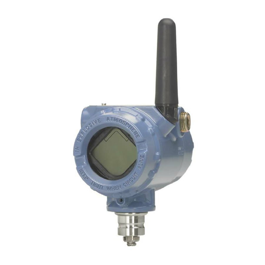
Emerson Rosemount 702 Reference Manual
Wireless discrete transmitter
Hide thumbs
Also See for Rosemount 702:
- Reference manual (96 pages) ,
- Quick start manual (60 pages) ,
- Quick installation manual (17 pages)

Related Manuals for Emerson Rosemount 702


Summary of Contents for Emerson Rosemount 702
- Page 1 Reference Manual 00809-0200-4702, Rev DA July 2017 ™ Rosemount 702 Wireless Discrete Transmitter...
-
Page 3: Table Of Contents
Reference Manual Contents 00809-0200-4702, Rev DA July 2017 Contents 1Section 1: Introduction Using this manual ..............1 Models covered . - Page 4 Contents Reference Manual 00809-0200-4702, Rev DA July 2017 3Section 3: Mounting, Wiring Switches, and Sensors: Models 702DX22 and 702DX61 Safety messages ..............15 Installing the transmitter.
- Page 5 Reference Manual Contents 00809-0200-4702, Rev DA July 2017 6Section 6: Configuration: Models 702DX32 and 702DX42 Safety messages ..............51 6.1.1 Ensuring proper switch connections.
- Page 6 Contents Reference Manual 00809-0200-4702, Rev DA July 2017 9Section 9: Operation and Maintenance: Models 702DX32 and 702DX42 Safety messages ..............79 Discrete input from switches .
- Page 7 Reference Manual Contents 00809-0200-4702, Rev DA July 2017 Ordering information............102 A.5.1 Wireless options .
- Page 8 Contents Reference Manual 00809-0200-4702, Rev DA July 2017 viii Contents...
- Page 9 Using non-nuclear qualified products in applications that require nuclear-qualified hardware or products may cause inaccurate readings. ™ For information on Rosemount nuclear-qualified products, contact an Emerson Sales Representative. Explosions could result in death or serious injury. Installation of this transmitter in an explosive environment must be in accordance with the ...
- Page 10 00809-0200-4702, Rev DA July 2017 The Rosemount 702 Transmitter and all other wireless devices should be installed only after the Emerson Wireless Gateway has been installed and is functioning properly. Wireless devices should also be powered up in order of proximity from the Gateway, beginning with the closest. This will result in a simpler and faster network installation.
-
Page 11: Using This Manual
Section 2: Configuration: Models 702DX22 and 702DX61 contains information on the configuration of the Rosemount 702 Transmitter so that it can be added to the wireless network. This configuration can be done using the AMS Suite Wireless Configurator or a Field Communicator. Field Communicator menu trees are here. -
Page 12: Models Covered
Section 9: Operation and Maintenance: Models 702DX32 and 702DX42 provides detailed information on operation of the Rosemount 702 Transmitter with various switch and sensor configurations. Also described are: Momentary discrete input detection and counting, discrete output switch function, and variable reporting and mapping. LCD display messages are shown. Power module replacement is described. -
Page 13: Transmitter Overview
Gateway, beginning with the closest. This will result in a simpler and faster network installation. Enable Active Advertising on the Gateway to ensure that new devices join the network faster. For more information see the Emerson Wireless Gateway Reference Manual. -
Page 14: Choosing An Installation Location And Position
1.3.3 Choosing an installation location and position When choosing an installation location and position, take into account access to the Rosemount 702 Transmitter. For best performance, the antenna should be vertical with space between objects in a parallel metal plane, such as a pipe or metal framework, as the pipes or framework may adversely affect the antenna’s performance. -
Page 15: Electrical
Electrical Caring for the power module The Rosemount 702 Transmitter is self-powered. The included Black Power Module contains two “C” size primary lithium/thionyl chloride batteries. Each battery contains approximately 2.5 grams of lithium, for a total of 5 grams in each pack. Under normal conditions, the battery materials are self-contained and are not reactive as long as the batteries and the power module are maintained. -
Page 16: Product Recycling/Disposal
Introduction Reference Manual 00809-0200-4702, Rev DA July 2017 Example The transmitter specification limit is 185 °F (85 °C). If the ambient temperature is 131 °F (55 °C) and the maximum process temperature to be measured is 1500 °F(815 °C), the maximum permissible connection head temperature rise is the transmitter specification limit minus the ambient temperature (moves 185 °F to 131 °F [85 to 55 °C]), or 86 °F (30 °C). -
Page 17: Safety Messages
Reference Manual Configuration: Models 702DX22 and 702DX61 00809-0200-4702, Rev DA July 2017 Section 2 Configuration: Models 702DX22 and 702DX61 Safety messages ..............page 7 Configuring the Device Sensor . -
Page 18: Configuring The Device Sensor
Remove the power module-side housing cover to expose the terminal block and HART Communication terminals, then connect the power module to power the unit for configuration. The Rosemount 702 Transmitter will receive any HART Communication from a Field Communicator, or AMS Wireless Configurator. -
Page 19: Configuring The Device Network
Reference Manual Configuration: Models 702DX22 and 702DX61 00809-0200-4702, Rev DA July 2017 Configuring the device network Field Communicator To communicate with the Gateway, and ultimately the information system, the transmitter must be configured to communicate with the wireless network. Using a Field Communicator or AMS Wireless Configurator, enter the Network ID and Join Key so they match the Network ID and Join Key of the Gateway and the other devices in the network. -
Page 20: Option Code 61(702Dx61)
Connect Tyco TraceTek and Fast Fuel sensor lead wires by matching the colors of wires to colors on terminal block. Figure 2-3. Field Communicator Connections P/N 00753-9200-0020 COMM For HART Communication, a Rosemount 702 DD is required. Configuration: Models 702DX22 and 702DX61... -
Page 21: Hart Menu Tree
Reference Manual Configuration: Models 702DX22 and 702DX61 00809-0200-4702, Rev DA July 2017 HART menu tree For ease of operation, changing setup, such as switch type, can be completed in several locations. 2.5.1 Dry contact inputs, measurement option code 22 (702DX22) Figure 2-4. -
Page 22: Liquid Hydrocarbon Detection, Measurement Option Code 61(702Dx61)
Configuration: Models 702DX22 and 702DX61 Reference Manual 00809-0200-4702, Rev DA July 2017 2.5.2 Liquid hydrocarbon detection, measurement option code 61(702DX61) Figure 2-5. Field Communicator Menu Tree, DD Revision 1, for Leak Detection 1. Network ID 1. Device Status 2. Join Device to Network 2. -
Page 23: Fast Key Sequence
Fast Key sequence for common transmitter functions. Note The Fast Key sequences assume that a current DD is being used: DD Rev 2 for dry contact inputs, and DD Rev 1 for leak detection. Table 2-1. Rosemount 702 Fast Key sequence Function Key sequence Menu items... - Page 24 Configuration: Models 702DX22 and 702DX61 Reference Manual 00809-0200-4702, Rev DA July 2017 Configuration: Models 702DX22 and 702DX61...
-
Page 25: Models 702Dx22 And 702Dx61
Mounting, Wiring Switches, and Sensors: Reference Manual Models 702DX22 and 702DX61 00809-0200-4702, Rev DA July 2017 Section 3 Mounting, Wiring Switches, and Sensors: Models 702DX22 and 702DX61 Safety messages ..............page 15 Installing the transmitter . -
Page 26: Installing The Transmitter
1. Install the switch according to standard installation practices making sure to use thread sealant on all of the connections. 2. Attach the Rosemount 702 Transmitter housing to the switch by using the pipe fittings threaded into the conduit entries. - Page 27 00809-0200-4702, Rev DA July 2017 Note ™ Wireless devices should only be powered up after the Emerson Wireless Gateway, in order of proximity from the Gateway beginning with the closest device. This results in a simpler and faster network installation.
-
Page 28: Remote Mount Configuration
1. Install the switch according to standard installation practices being sure to use thread sealant on all of the connections. 2. Run wiring (and conduit, if necessary) from the switch to the Rosemount 702 Transmitter. 3. Pull the wiring through the threaded conduit entry. -
Page 29: Wiring Switches And Sensors
Wireless output specifications Dual input The Rosemount 702 Transmitter will accept the input from one or two single pole single throw switches on inputs S1 and S2. The wireless output of the transmitter will be both a primary variable (PV) and a secondary variable (SV). - Page 30 July 2017 Dual input, limit contact logic When configured for Limit contact logic, the Rosemount 702 Transmitter will accept the input from two single pole single throw switches on inputs S1 and S2, and will use limit contact logic for the determination of the wireless outputs.
-
Page 31: Liquid Hydrocarbon Detection, Measurement Option Code 61(702Dx61)
The connections to the Fast Fuel Sensor TraceTek Sensing cable are made by matching the appropriately colored wires to the matching colored termination lugs. The Rosemount 702 Transmitter can support up to three Tyco Fast Fuel Sensors. These sensors are ... - Page 32 Note All part numbers on this page refer to products sold by Tyco Thermo Controls, LLC. The Rosemount 702 Transmitter can support up to 500 ft. (150 m) of TraceTek hydrocarbon or solvent sensor cable (TT5000 or TT5001 series). The total amount of sensor cable connected to a single transmitter is not to exceed 500 ft.
-
Page 33: Lcd Display
Mounting, Wiring Switches, and Sensors: Reference Manual Models 702DX22 and 702DX61 00809-0200-4702, Rev DA July 2017 Figure 3-12. Fuel Sensor Cable Wiring TT-MLC-MC-BLK (leader cable) TT5000/TT5001 Sensor cable (up to 500 ft.) C. TT-MET-MC (end termination) TT-MJC-xx-MC-BLK (optional jumper cable) E. -
Page 34: Grounding The Transmitter
C. LCD cover Grounding the transmitter The Rosemount 702 Transmitter operates with the housing grounded or floating. Floating systems, however, can cause extra noise that may affect many types of readout devices. If the signal appears noisy or erratic, grounding at a single point may solve the problem. Grounding of the electronics enclosure should be done in accordance with local and national installation codes. - Page 35 2. Ensure that the transmitter housing is electrically isolated from the switch wiring. A. Float switch B. Shield ground point C. Rosemount 702 Transmitter Option 2: 1. Ground switch wiring shield at the switch. 2. Ensure that the switch wiring and shield are electronically isolated from the transmitter housing.
- Page 36 Mounting, Wiring Switches, and Sensors: Reference Manual Models 702DX22 and 702DX61 00809-0200-4702, Rev DA July 2017 Mounting, Wiring Switches, and Sensors: Models 702DX22 and 702DX61...
-
Page 37: Safety Messages
Gateway has been installed and is functioning properly. Wireless devices should be powered up in order of proximity from the gateway, beginning with the ™ device closest to the Emerson Wireless Gateway. This will result in a simpler and faster network installation. -
Page 38: Configuring The Transmitter To Communicate With The Wireless Network
If the Network ID and Join Key are not identical, the Rosemount 702 Transmitter will not communicate with the network. The Network ID and Join Key may be obtained from the Emerson Wireless Gateway on the Setup>Network>Settings page on the web server,... -
Page 39: Verifying Operation
Communicator, using the Gateway's integrated web interface, or by using AMS Suite Wireless Configurator. If the Rosemount 702 Transmitter was configured with the Network ID and Join Key, and sufficient time has passed, the transmitter will be connected to the network. - Page 40 S R C H N G N E G O T L I M - O P Connecting with a Field Communicator A Rosemount 702 DD is required for HART communication. For connecting with a Field Communicator, refer to Figure 2-3 on page Function...
-
Page 41: Ams Wireless Configurator
Reference Manual Commissioning: Models 702DX22 and 702DX61 00809-0200-4702, Rev DA July 2017 Figure 4-4. Gateway Explorer Page 4.5.1 AMS Wireless Configurator When the device has joined the network, it will appear in the Device Manager as illustrated below: Troubleshooting If the device is not joined to the network after power up, verify the correct configuration of the Network ID and Join Key, and verify that Active Advertising has been enabled on the Gateway. - Page 42 Commissioning: Models 702DX22 and 702DX61 Reference Manual 00809-0200-4702, Rev DA July 2017 Operation and Maintenance...
-
Page 43: Models 702Dx22 And 702Dx61
Operation and Maintenance: Reference Manual Models 702DX22 and 702DX61 00809-0200-4702, Rev DA July 2017 Section 5 Operation and Maintenance: Models 702DX22 and 702DX61 Safety Messages ..............page 33 Discrete input from switches and sensors . -
Page 44: Discrete Input From Switches And Sensors
Operation and Maintenance: Reference Manual Models 702DX22 and 702DX61 00809-0200-4702, Rev DA July 2017 Discrete input from switches and sensors 5.2.1 Dry contact inputs, measurement option code 22 (702DX22) Figure 5-1. Terminal Diagram 5.2.2 Wireless output specifications Dual input ™ The Rosemount 702 Wireless Discrete Transmitter will accept the input from one or two single pole single throw switches on inputs S1 and S2. - Page 45 FALSE (0.0) Dual input, limit contact logic When configured for limit contact logic, the Rosemount 702 Transmitter will accept the input from two single pole single throw switches on inputs S1 and S2, and will use limit contact logic for the determination of the wireless outputs.
-
Page 46: Liquid Hydrocarbon Detection, Measurement Option Code 61 (702Dx61)
Operation and Maintenance: Reference Manual Models 702DX22 and 702DX61 00809-0200-4702, Rev DA July 2017 Figure 5-4. Dual Input, Opposing Contact Switch inputs Wireless outputs Open Open FAULT(NaN) FAULT(NaN) Open Closed FALSE (0.0) FALSE (0.0) Closed Open TRUE (1.0) TRUE (1.0) Closed Closed FAULT(NaN) - Page 47 Using the AMS Device Manager with the liquid hydrocarbon detection option The following figures show how the AMS Device Manager overview screen looks for the Rosemount 702 Transmitter with liquid hydrocarbon detection option, for each of the leak sensor conditions: Figure 5-7.
- Page 48 Operation and Maintenance: Reference Manual Models 702DX22 and 702DX61 00809-0200-4702, Rev DA July 2017 Figure 5-8. Leak Status Figure 5-9. Leak Sensor Not Connected Status Table 5-1. Liquid Hydrocarbon Detection Interface, for Modbus mapping Description/interpretation Normal condition, no leak detected, sensor status good 1.0 or 0.0 Leak detected, sensor status good Sensor Not Connected, Assume Leak, take appropriate action...
- Page 49 Tyco TraceTek sensors must be installed as per manufacturer recommendations. Do not run the Rosemount 702 Transmitter for long periods (more than two weeks) with a Tyco fuel sensor in the leak state as this will more rapidly deplete the power module.
-
Page 50: Lcd Display Screen Messages
Detection, Measurement Option Code 61. 5.3.1 Startup screen sequence The following screens will display when the power module is first connected to the Rosemount 702 Transmitter: X X X X X All Segments On: used to visually determine if there are any... - Page 51 Operation and Maintenance: Reference Manual Models 702DX22 and 702DX61 00809-0200-4702, Rev DA July 2017 S N S R 2 SV Screen - Discrete input 2 True D E V TV Screen - feature board temperature value 2 5. 2 5 d e g c S u p l y QV Screen - voltage reading at the power module terminals...
-
Page 52: Diagnostic Button Screen Sequence
Operation and Maintenance: Reference Manual Models 702DX22 and 702DX61 00809-0200-4702, Rev DA July 2017 5.3.2 Diagnostic button screen sequence The following five screens will display when the device is operating properly and the Diagnostic Button has been pressed: A b c d e Device Information - Tag: user entered tag which is eight characters long - will not display if all characters are blank f g h... -
Page 53: Network Connection Status Screens
Operation and Maintenance: Reference Manual Models 702DX22 and 702DX61 00809-0200-4702, Rev DA July 2017 5.3.3 Network connection status screens These screens display the network status of the device. Only one will be shown in the fourth position of the diagnostic button screen sequence. n e t w k Diagnostic Button Screen 4.1: the device is attempting to start the radio... - Page 54 Operation and Maintenance: Reference Manual Models 702DX22 and 702DX61 00809-0200-4702, Rev DA July 2017 n e t w k Diagnostic Button Screen 4.6: the device is attempting to join a network N E G O T n e t w k Diagnostic Button Screen 4.7: the device is connected to the Network, but is in a “Quarantined”...
-
Page 55: Device Diagnostic Screens
Operation and Maintenance: Reference Manual Models 702DX22 and 702DX61 00809-0200-4702, Rev DA July 2017 5.3.4 Device diagnostic screens The following screens will show the device diagnostics depending on the state of the device and will appear after screen 5 of the Diagnostic Button Screen Sequence. Device Information - Status: there is a critical error which may D E V prevent the device from operating correctly. - Page 56 Operation and Maintenance: Reference Manual Models 702DX22 and 702DX61 00809-0200-4702, Rev DA July 2017 S u p l y QV Screen - voltage reading at the power supply terminals 7. 2 1 v o l t s a l e r t Alert Screen - at least one alert is present - this screen will not display if no alerts are present p r e s n t...
- Page 57 Operation and Maintenance: Reference Manual Models 702DX22 and 702DX61 00809-0200-4702, Rev DA July 2017 10. Diagnostic Button Screen 7.2: the terminal voltage is below the s u p l y recommended operating range - if this is a self-operated device, the power module should be replaced - for line powered devices, the supply voltage should be increased l o w...
-
Page 58: Replacing The Power Module
Operation and Maintenance: Reference Manual Models 702DX22 and 702DX61 00809-0200-4702, Rev DA July 2017 Note Use Rosemount wireless LCD display part number: 00753-9004-0002. Replacing the power module Expected power module life is ten years at reference conditions. When the power module needs to be replaced, remove the power module cover and the depleted power ™... -
Page 59: Service Support
To expedite the return process outside of North America, contact your Emerson representative, Within the United States, call the Emerson Response Center toll-free number 1 800 654 7768. The center, which is available 24 hours a day, will assist you with any needed information or materials. -
Page 60: Rev Da July
Operation and Maintenance: Reference Manual Models 702DX22 and 702DX61 00809-0200-4702, Rev DA July 2017 Operation and Maintenance: Models 702DX22 and 702DX61... -
Page 61: Safety Messages
Reference Manual Configuration: Models 702DX32 and 702DX42 00809-0200-4702, Rev DA July 2017 Section 6 Configuration: Models 702DX32 and 702DX42 Safety messages ..............page 51 Discrete channel configuration . -
Page 62: Ensuring Proper Switch Connections
The Rosemount 702 Transmitter will receive any HART Communication from a Field Communicator, or AMS Wireless Configurator. When using a Field Communicator, any configuration changes must be sent to the transmitter using the Send key (F2). -
Page 63: Dry Contact Inputs, Measurement Option Code
The final device network configuration piece is the update rate which, by default, is 1 minute. It can be ™ changed at commissioning, or at any time, by using AMS Wireless Configurator or the Emerson Wireless Gateway’s web server. The Update Rate should be between one second and 60 minutes. To change the update rate with a Field Communicator, use the Fast Key Sequence: 2, 2, 1, 3. - Page 64 Configuration: Models 702DX32 and 702DX42 Reference Manual 00809-0200-4702, Rev DA July 2017 Figure 6-2. Field Communicator Connections P/N 00753-9200-0020 COMM For HART communication, a Rosemount 702 DD is required. Configuration: Models 702DX32 and 702DX42...
-
Page 65: Hart Menu Tree
Reference Manual Configuration: Models 702DX32 and 702DX42 00809-0200-4702, Rev DA July 2017 HART menu tree For ease of operation, changing setup, such as switch type, can be completed in several locations. Figure 6-3. Overview Home 1 Overview Overview Active Alerts Device Status 2 Configure 1 Device Status... - Page 66 Configuration: Models 702DX32 and 702DX42 Reference Manual 00809-0200-4702, Rev DA July 2017 Figure 6-4. Configure Home 1 Overview Configure 2 Configure 1 Guided Setup Guided Setup 3 Service Tools 2 Manual Setup 1 Join Device To Network 2 Configure Update Rate 3 Configure Discrete Channels 4 Configure Device Display 5 Basic Setup...
- Page 67 Reference Manual Configuration: Models 702DX32 and 702DX42 00809-0200-4702, Rev DA July 2017 Figure 6-5. Service Tools Service Tools Home 1 Alerts Alerts 1 Overview 1 Refresh Alerts 2 Variables 2 Configure 2 Active Alerts 3 Trends Active Alerts 3 Service Tools 3 History 4 Communication 1 Good- only if no alerts...
-
Page 68: Fast Key Sequence
Configuration: Models 702DX32 and 702DX42 Reference Manual 00809-0200-4702, Rev DA July 2017 6.4.1 Fast Key sequence Table 6-1 lists the Fast Key sequence for common transmitter functions. Note The Fast Key sequences assume that a current DD is being used: DD Rev 2 for dry contact inputs, and DD Rev 1 for leak detection. -
Page 69: Models 702Dx32 And 702Dx42
Mounting, Wiring Switches, and Output Circuits: Reference Manual Models 702DX32 and 702DX42 00809-0200-4702, Rev DA July 2017 Section 7 Mounting, Wiring Switches, and Output Circuits: Models 702DX32 and 702DX42 Safety messages ..............page 59 Installing the transmitter . -
Page 70: Installing The Transmitter
1. Install the switch according to standard installation practices making sure to use thread sealant on all of the connections. 2. Attach the Rosemount 702 Transmitter housing to the switch by using the pipe fittings threaded into the conduit entries. - Page 71 00809-0200-4702, Rev DA July 2017 Note ™ Wireless devices should only be powered up after the Emerson Wireless Gateway, in order of proximity from the Gateway beginning with the closest device. This results in a simpler and faster network installation.
-
Page 72: Remote Mount
1. Install the switch according to standard installation practices being sure to use thread sealant on all of the connections. 2. Run wiring (and conduit, if necessary) from the switch to the Rosemount 702 Transmitter. 3. Pull the wiring through the threaded conduit entry. -
Page 73: Wiring Switches And Sensors
Dry contact inputs, measurement option code 32, 42 (702DX32, 702DX42) Terminal block The Rosemount 702 Transmitter has a pair of screw terminals for each of two channels, and a pair of communication terminals. These terminals are labeled as follows: CH1+:... - Page 74 Dual input Dual input, limit contact logic When configured for limit contact logic, the Rosemount 702 Transmitter will accept the input from two single pole single throw switches on inputs CH1 and CH2, and will use limit contact logic for the determination of the wireless outputs.
-
Page 75: Output Circuits, Measurement Option Code 42 (702Dx42)
Output circuits, measurement option code 42 (702DX42) The Rosemount 702 Transmitter has two channels that can each be configured for discrete input or output. Inputs must be dry contact switch inputs and these were described in a preceding section of this document. - Page 76 Figure 7-11. Dual Output Circuits with Common Ground If two output circuits are connected to a single Rosemount 702 Transmitter with a single power supply, both CH + and CMN terminals must be connected to each output circuit. The negative power supply wires must be at the same voltage and connected to both CMN terminals.
-
Page 77: Safety Shower And Eye Wash Monitoring
Figure 7-13. Wiring an Interposing Relay to Switch Greater Currents or Voltages 7.3.4 Safety shower and eye wash monitoring The Rosemount 702 Transmitter can be used to monitor safety showers and eye wash stations by using ™ switch kits provided by TopWorx , an Emerson company. - Page 78 When the shower valve is activated (valve open) by pulling down on the handle, the TopWorx switch is activated (closed switch) and the Rosemount 702 Transmitter senses that switch closure. This switch state is then transmitted by the transmitter to the Gateway, which then sends that information to the control host or alert system.
- Page 79 When the eye wash valve is activated (valve open) by pushing down on the hand paddle, the TopWorx switch is activated (closed switch) and the Rosemount 702 Transmitter senses that switch closure. This switch state is then transmitted by the transmitter to the Gateway, which then sends that information to the control host or alert system.
-
Page 80: Lcd Display
Mounting, Wiring Switches, and Output Circuits: Reference Manual Models 702DX32 and 702DX42 00809-0200-4702, Rev DA July 2017 Installation of safety shower and eye wash monitoring kits Drawings to aid in the installation of safety shower and eye wash kits can be found in Appendix D: Safety Shower Monitoring on page... -
Page 81: Grounding The Transmitter
July 2017 Grounding the transmitter The Rosemount 702 Transmitter operates with the housing grounded or floating. Floating systems, however, can cause extra noise that may affect many types of readout devices. If the signal appears noisy or erratic, grounding at a single point may solve the problem. Grounding of the electronics enclosure should be done in accordance with local and national installation codes. - Page 82 Mounting, Wiring Switches, and Output Circuits: Reference Manual Models 702DX32 and 702DX42 00809-0200-4702, Rev DA July 2017 Mounting, Wiring Switches, and Output Circuits: Models 702DX32 and 702DX42...
-
Page 83: Safety Messages
Reference Manual Commissioning: Models 702DX32 and 702DX42 00809-0200-4702, Rev DA July 2017 Section 8 Commissioning: Models 702DX32 and 702DX42 Safety messages ..............page 73 Configuring wireless network communication . -
Page 84: Configuring Wireless Network Communication
Communicator, using the Gateway's integrated web interface, or by using AMS Wireless Configurator. If the Rosemount 702 Transmitter was configured with the Network ID and Join Key, and sufficient time has passed, the transmitter will be connected to the network. -
Page 85: Troubleshooting
When the status bar is filled, the device is successfully connected to the wireless network. Start-up Display Sequence: When the Rosemount 702 Transmitter is first powered up, the LCD display will display a sequence of screens: All Segments On, Device Identification, Device Tag, and then the user-chosen variables of the Periodic Display. - Page 86 S R C H N G N E G O T L I M - O P Field Communicator A Rosemount 702 DD is required for HART communication. For connecting with a Field Communicator, refer to Figure 2-3 on page Function...
-
Page 87: Ams Wireless Configurator
Reference Manual Commissioning: Models 702DX32 and 702DX42 00809-0200-4702, Rev DA July 2017 Figure 8-5. Emerson Wireless Gateway Explorer Page 8.3.1 AMS Wireless Configurator When the device has joined the network, it will appear in the Device Manager as illustrated below:... - Page 88 Commissioning: Models 702DX32 and 702DX42 Reference Manual 00809-0200-4702, Rev DA July 2017 Changing the network ID and join key The Network ID and Join Key may be obtained from the Gateway on the Setup>Network>Settings page on the web interface (see Figure 8-5 on page 77).
-
Page 89: Models 702Dx32 And 702Dx42
Operation and Maintenance: Reference Manual Models 702DX32 and 702DX42 00809-0200-4702, Rev DA July 2017 Section 9 Operation and Maintenance: Models 702DX32 and 702DX42 Safety messages ..............page 79 Discrete input from switches . -
Page 90: Discrete Input From Switches
9.2.1 Dry contact inputs, measurement option code 32, 42 (702DX32, 702DX42) The Rosemount 702 Transmitter has a pair of screw terminals for each of two channels, and a pair of communication terminals. These terminals are labeled as follows: CH1+: Channel 1 Positive... - Page 91 FALSE (0.0) Dual input, limit contact logic When configured for limit contact logic, the Rosemount 702 Transmitter will accept the input from two single pole single throw switches on inputs CH1 and CH2, and will use limit contact logic for the determination of the wireless outputs.
-
Page 92: Momentary Discrete Inputs, Measurement Option Code 32 And 42
Momentary discrete inputs, measurement option code 32 and 42 (702DX32, 702DX42) The Rosemount 702 Transmitter is capable of measuring momentary discrete inputs of 10 millisecond or more in duration, regardless of the wireless update rate. At each wireless update, the device reports current discrete input state and an accumulating count of close-open cycles for each input channel. - Page 93 Figure 9-6. Reporting of Current Discrete State and Count in AMS Wireless Configurator Setting variable reporting in AMS Wireless Configurator The Rosemount 702 Transmitter has two choices for variable reporting: Classic - Discrete State Only, or Enhanced – Discrete State and Count. In the Classic variable reporting mode, the transmitter will report variables exactly like the previous version of the device (measurement option code 22).
- Page 94 Setting the reported value in AMS Wireless Configurator The Rosemount 702 Transmitter reports the discrete state of switches wired to the input channels. There are various pairs of discrete states that correspond to an open or closed input switch. This pair of discrete states is called the Reported Value and can be set in AMS Wireless Configurator by going to Configure >...
- Page 95 Switch” on the table above. Variable reporting, limit contact or opposing contact logic If the Rosemount 702 Transmitter has two inputs and is set for limit contact or opposing contact logic, there is a different list of reported values. Table 9-3 describes the values that are reported as a function of the Reported Value setting, and the four possible discrete states of True, False, Fault and Travel.
-
Page 96: Discrete Output Circuits
Discrete output switch functionality The discrete output of the Rosemount 702 Transmitter is driven by the host control system, through the Emerson Wireless Gateway, and out to the transmitter. The time required for this wireless communication from the gateway to the transmitter is dependent on many factors, including the size and topology of the network and the total amount of downstream traffic on the wireless network. - Page 97 Connecting two output circuits with a single power supply If two output circuits are connected to a single Rosemount 702 Transmitter with a single power supply, both CH + and CMN terminals must be connected to each output circuit. The negative power supply wires must be at the same voltage and connected to both CMN terminals.
- Page 98 Setting the reported value Though the output switch state is driven by command from the control host, the Rosemount 702 Transmitter then reports back the state of the output switch via the PV and SV. There are various pairs of discrete states that correspond to an open or closed output switch.
- Page 99 Reference Manual Operation and Maintenance: Models 702DX32 and 702DX42 00809-0200-4702, Rev DA July 2017 Analog Value: The analog value is seen on the gateway web interface under the PV or SV. This is also the value that is reported through the gateway to a control host that requires an analog floating point value for PV or SV.
-
Page 100: Modbus And Opc Mapping
Following is a table of parameters that can be used for Modbus and OPC mapping. These parameters are used by the Emerson Wireless Gateway and can be found in the web interface of the gateway. some of these parameters are analog values and some are discrete, and this is noted in the description. - Page 101 Reference Manual Operation and Maintenance: Models 702DX32 and 702DX42 00809-0200-4702, Rev DA July 2017 A b c d e Device Information - Tag: user entered tag which is 8 characters long - will not display if all characters are blank f g h PV Screen - Discrete State of Channel 1 True...
-
Page 102: Diagnostic Button Screen Sequence
Operation and Maintenance: Models 702DX32 and 702DX42 Reference Manual 00809-0200-4702, Rev DA July 2017 Channel 1 Count of close/open cycles X X X X X X Counts Channel 2 Count of close/open cycles X X X X X X Counts 9.5.2 Diagnostic button screen sequence The following five screens will display when the device is operating properly and the Diagnostic Button... -
Page 103: Network Connection Status Screens
Reference Manual Operation and Maintenance: Models 702DX32 and 702DX42 00809-0200-4702, Rev DA July 2017 Diagnostic Button Screen 4.9: the device has joined a n e t w k network and has been fully configured and has multiple parents S u p l y Diagnostic Button Screen 5: voltage reading at the power 7. - Page 104 Operation and Maintenance: Models 702DX32 and 702DX42 Reference Manual 00809-0200-4702, Rev DA July 2017 Diagnostic Button Screen 4.4: the device is in a n e t w k disconnected state and requires a “Force Join” command to join the network D I S C N T N E T w K Diagnostic Button Screen 4.5: the device is searching for...
-
Page 105: Device Diagnostic Screens
Reference Manual Operation and Maintenance: Models 702DX32 and 702DX42 00809-0200-4702, Rev DA July 2017 n e t w k Diagnostic Button Screen 4.9: the device has joined a network and has been fully configured and has multiple parents 9.5.4 Device diagnostic screens The following screens will show the device diagnostics depending on the state of the device, continuing after Diagnostic Button Screen 5. - Page 106 Operation and Maintenance: Models 702DX32 and 702DX42 Reference Manual 00809-0200-4702, Rev DA July 2017 Diagnostic Button Screen 8: the device cannot retrieve r a d i o information from the radio in the device - the device may still be operational and publishing HART data f a i l u r Diagnostic Button Screen 9: configuration of the transmitter is invalid such that critical operation of the...
-
Page 107: Replacing The Power Module
Reference Manual Operation and Maintenance: Models 702DX32 and 702DX42 00809-0200-4702, Rev DA July 2017 Diagnostic Button Screens 13 +: All of the periodic screens except supply voltage will now be displayed to conclude the Diagnostic Button Screen Sequence. These screens are: Channel 1 State Channel 2 State Electronics Temperature... -
Page 108: Service Support
To expedite the return process outside of North America, contact your Emerson representative, Within the United States, call the Emerson Response Center toll-free number 1 800 654 7768. The center, which is available 24 hours a day, will assist you with any needed information or materials. -
Page 109: Aappendix A: Specifications And Reference Data
Specifications and Reference Data Reference Manual July 2017 00809-0200-4702, Rev DA Appendix A Specifications and Reference Data Functional specifications ............. page 99 Physical specifications . -
Page 110: Physical Specifications
Reference Manual Specifications and Reference Data July 2017 00809-0200-4702, Rev DA A.2 Physical specifications Weight Low - copper aluminum A.2.1 Electrical connections Transmitter without LCD display—4.6 lbs. (2.0 kg) Wireless power module Transmitter M5 LCD display—4.7 lbs (2.1 kg) Stainless Steel Replaceable, Intrinsically Safe Lithium-Thionyl Chloride power module with PBT polymer enclosure. -
Page 111: Dimensional Drawings
5.51 [140] A. Extended range, external antenna B. External antenna Dimensions are in inches (millimeters) Figure A-2. Rosemount 702 Transmitter Mounting Configurations with Optional Mounting Bracket 6.20 (158) A. 2-in. U-bolt for pipe mounting B. 1-in. U-bolt for transmitter mounting... -
Page 112: Ordering Information
July 2017 00809-0200-4702, Rev DA A.5 Ordering information Rosemount 702 Wireless Discrete Transmitter Ordering Information Table A-1. The starred offerings (★) represent the most common options and should be selected for best delivery. The non-starred offerings are subject to additional delivery lead time. -
Page 113: Wireless Options
Reference Manual July 2017 00809-0200-4702, Rev DA Rosemount 702 Wireless Discrete Transmitter Ordering Information Table A-1. The starred offerings (★) represent the most common options and should be selected for best delivery. The non-starred offerings are subject to additional delivery lead time. - Page 114 Reference Manual Specifications and Reference Data July 2017 00809-0200-4702, Rev DA Specifications and Reference Data...
-
Page 115: European Directive Information
Nearly every country requires this type of product The US National Electrical Code (NEC) and the Canadian certification. Emerson is working with governmental Electrical Code (CEC) permit the use of Division marked agencies around the world to supply fully compliant... -
Page 116: Canada
≤ +70 °C) parameters parameters (option code 32) (option code 61) For use with Rosemount SmartPower power module part number 753-9220-0001, or for use with Emerson = 6.51 V = 7.8 V SmartPower option 701PBKKF. = 13.37 mA = 92 mA... -
Page 117: International
= 92 mA installation to prevent electrostatic charge build-up. = 21.76 mW = 180 mW 3. The Rosemount 702 Transmitter enclosure may be = 0.216 μF = 10 nF made of aluminum alloy and given a protective = 21.78 μF = 9.2 μF... -
Page 118: Japan
Reference Manual Product Certifications July 2017 00809-0200-4702, Rev DA B.12 EAC - Belarus, Terminal parameters Fuel sensor Sensor terminal Kazakhstan, Russia (option code 42) terminal parameters parameters (option (option code 32) Sensor Switch IM Technical Regulation Customs Union (EAC) Intrinsic code 61) Safety = 6.6 V... -
Page 119: Installation Drawings
Product Certifications Reference Manual July 2017 00809-0200-4702, Rev DA B.13 Installation Drawings Figure B-1. Rosemount 702 FM Intrinsically Safe Installation Drawing Product Certifications... - Page 120 Reference Manual Product Certifications July 2017 00809-0200-4702, Rev DA Product Certifications...
- Page 121 Product Certifications Reference Manual July 2017 00809-0200-4702, Rev DA Figure B-2. Rosemount 702 CSA Intrinsic Safety Installation Drawing Product Certifications...
- Page 122 Reference Manual Product Certifications July 2017 00809-0200-4702, Rev DA Product Certifications...
- Page 123 Product Certifications Reference Manual July 2017 00809-0200-4702, Rev DA Product Certifications...
- Page 124 Product Certifications Reference Manual July 2017 00809-0200-4702, Rev DA Product Certifications...
-
Page 125: Safety Messages
If the supplied remote mount antenna kit is not installed per these instructions, Emerson is not responsible for wireless performance or non-compliance with spectrum regulations. -
Page 126: Functional Specifications
Reference Manual High Gain Remote Antenna Option July 2017 00809-0200-4702, Rev DA Functional specifications Output ® WirelessHART 2.4 GHz DSSS (direct sequence spread spectrum). Radio frequency power output from antenna: High gain remote (WN option) antenna: maximum of 40 mW (16 dBm) EIRP (equivalent isotropically ... -
Page 127: Installation Considerations
High Gain Remote Antenna Option Reference Manual July 2017 00809-0200-4702, Rev DA Installation considerations Antenna mounting Mount antenna vertically (±5°) Antenna height mount antenna 14 ft. (4,3 m) above infrastructure with clear line of sight. Coaxial cable Ensure that coaxial cable is securely affixed to the mast to avoid excessive cable movement. Installing coaxial drip loop Ensure a drip loop is installed not closer than 1 ft. -
Page 128: Dimensional Drawings
Reference Manual High Gain Remote Antenna Option July 2017 00809-0200-4702, Rev DA Dimensional drawings Figure C-1. Device Connection and RF Lightning Arrestor 2.75 4 PLS 20.2-ft. [513m] A. Antenna B. Mounting bracket C. Mounting arrester D. 25 ft. (7.5 m) cable E. -
Page 129: Installing The High Gain Remote Antenna
High Gain Remote Antenna Option Reference Manual July 2017 00809-0200-4702, Rev DA Installing the high gain remote antenna 1. Mount the transmitter following best practice mounting procedures as outlined in the Quick Start Guide and Manual. 2. Connect the RF lightning protector to the device and tighten. RF lightning protector 3. - Page 130 Reference Manual High Gain Remote Antenna Option July 2017 00809-0200-4702, Rev DA 4. Unwind coaxial cable and connect the cable to both the antenna and the lightning protector connected to the transmitter, leaving one loop minimum for a drip loop. Ensure the drip loop is lower than the device, allowing water to flow away from the device.
- Page 131 High Gain Remote Antenna Option Reference Manual July 2017 00809-0200-4702, Rev DA 6. Attach U-bolts to mounting bracket in correct orientation ensuring that antenna will be positioned in a vertical position. 7. Tighten U-bolts to mast and ensure that antenna is pointed in a vertical direction. High Gain Remote Antenna Option...
- Page 132 Reference Manual High Gain Remote Antenna Option July 2017 00809-0200-4702, Rev DA High Gain Remote Antenna Option...
-
Page 133: Dappendix D: Safety Shower Monitoring
Safety Shower Monitoring Reference Manual July 2017 00809-0200-4702, Rev DA Appendix D Safety Shower Monitoring Installation instructions ............. page 123 Installation drawings . - Page 134 Safety Shower Monitoring Reference Manual July 2017 00809-0200-4702, Rev DA 10. Loosely attach the switch mounting bracket to the eyewash mounting brackets with four –20 x 0.75 hex head screws, four ” plain washers, four 1/4” lock washers, and four –20 hex nuts.
-
Page 135: Installation Drawings
Safety Shower Monitoring Reference Manual July 2017 00809-0200-4702, Rev DA Installation drawings Figure D-1. 10 Series GO Switch Mounted on Universal Thermal Shower Safety Shower Monitoring... - Page 136 Reference Manual Safety Shower Monitoring July 2017 00809-0200-4702, Rev DA Figure D-2. 10 Series GO Switch Mounted on Universal Thermal Eyewash Safety Shower Monitoring...
- Page 137 Safety Shower Monitoring Reference Manual July 2017 00809-0200-4702, Rev DA Figure D-3. 10 Series GO Switch Universal Shower Safety Shower Monitoring...
- Page 138 Reference Manual Safety Shower Monitoring July 2017 00809-0200-4702, Rev DA Figure D-4. Type 10 Series Switch with or without Latcher Safety Shower Monitoring...
- Page 139 Index Reference Manual July 2017 00809-0200-4702, Rev DA Index ..... . . 3, 29, 31, 75, 77 ..........23, 70 Active Advertising .
- Page 140 Index Reference Manual July 2017 00809-0200-4702, Rev DA ......... 29 update rate .
- Page 142 Terms and Conditions of Sale page. +65 6777 0947 The Emerson logo is a trademark and service mark of Emerson Electric Co. Enquiries@AP.Emerson.com Rosemount and Rosemount logotype are trademarks of Emerson. TopWorx, GO Switch, Smart Power, Rosemount and Rosemount logotype are trademarks of Emerson.
Need help?
Do you have a question about the Rosemount 702 and is the answer not in the manual?
Questions and answers