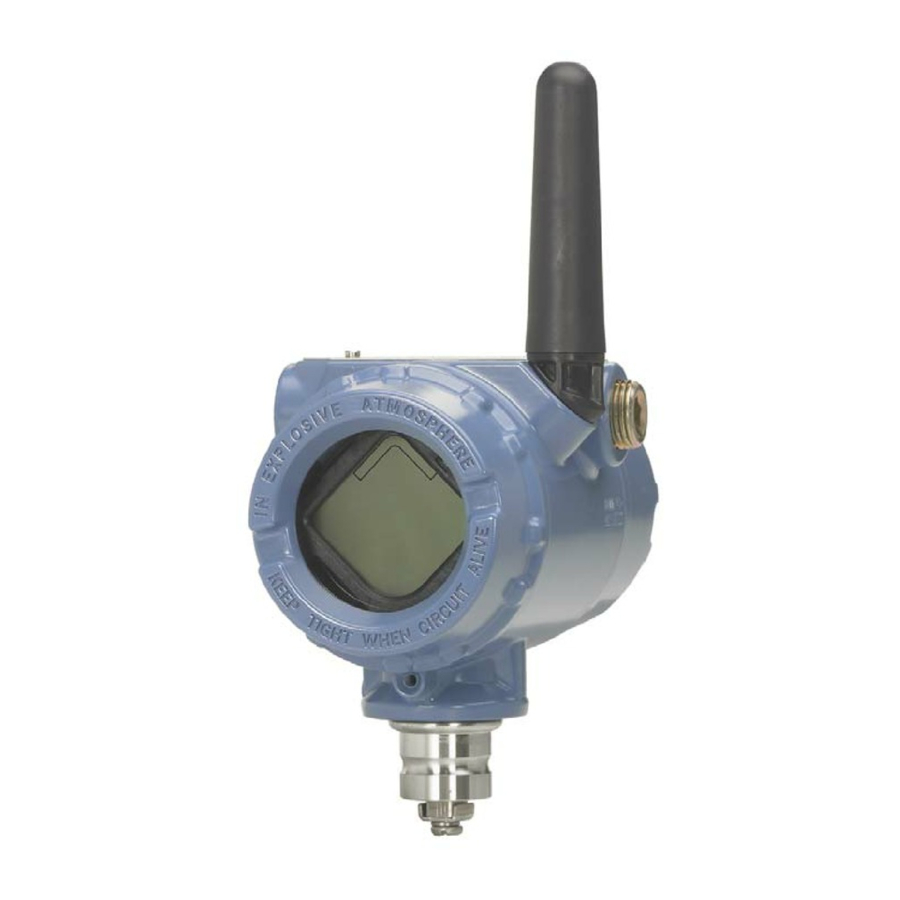
Emerson Rosemount 702 Quick Start Manual
Wireless discrete transmitter
Hide thumbs
Also See for Rosemount 702:
- Reference manual (142 pages) ,
- Quick start manual (60 pages) ,
- Quick installation manual (17 pages)

Related Manuals for Emerson Rosemount 702


Summary of Contents for Emerson Rosemount 702
- Page 1 Quick Start Guide 00825-0200-4702, Rev HA April 2021 ™ Rosemount 702 Wireless Discrete Transmitter...
-
Page 2: Table Of Contents
Contents About this guide...........................3 Wireless considerations........................4 Physical installation........................7 Device network configuration....................14 Verify operation......................... 15 Reference information: wiring switch inputs, output circuits, and leak sensors......19 Safety shower and eye wash monitoring..................40 Product certification........................42 Emerson.com/Rosemount... -
Page 3: About This Guide
April 2021 Quick Start Guide About this guide This guide provides basic guidelines for the Rosemount 702. It does not provide instructions for detailed configuration, diagnostics, maintenance, service, troubleshooting, or installations. Refer to the Rosemount 702 Reference Manual for more instruction. This guide and the manual are available electronically on Emerson.com/Rosemount. -
Page 4: Wireless Considerations
Install the Power Module, ™ SmartPower Solutions model number 701PBKKF into the Rosemount 702 Transmitter to power the device. Wireless devices should be powered up in order of proximity from the Gateway, beginning with the closest device, then working outward from the Gateway. - Page 5 Field Communicator connections The power module needs to be installed before the Field Communicator can ® interface with the Rosemount 702 Wireless transmitter. For HART Wireless Transmitter communication via a Field Communicator, a Rosemount 702 Wireless Device Dashboard (DD) is required. To obtain the latest DD, visit the Field Communicator System Software and Device Description site at: Emerson.com/Field-Communicator.
- Page 6 April 2021 Figure 2-3: Connection Diagram A. Communication terminals B. Handheld communicator C. HART modem The transmitter and all other wireless devices should not be set up until after the Wireless Gateway has been installed and is functioning properly. Emerson.com/Rosemount...
-
Page 7: Physical Installation
1. Install the switch according to standard installation practices making sure to use thread sealant on all connections. 2. Attach the Rosemount 702 Transmitter housing to the switch using the threaded conduit entry. 3. Attach the switch wiring to the terminals as indicated on the wiring... - Page 8 6. Position antenna vertically, either straight up or straight down. The antenna should be approximately 3 ft. (0.91 m) from any large structures or buildings, to allow clear communication to other devices. Emerson.com/Rosemount...
- Page 9 April 2021 Quick Start Guide Remote mount installation Figure 3-2: Remote Mount A. Rosemount 702 Transmitter B. Float switch Procedure 1. Install the switch according to standard installation practices making sure to use thread sealant on all connections. 2. Run wiring (and conduit if necessary) from the switch to the Rosemount 702 Transmitter.
- Page 10 A. 2-in. U-bolt for pipe fitting Remote antenna (optional) The high gain, remote antenna options provide flexibility for mounting the device based on wireless connectivity, lightning protection, and current work practices. Emerson.com/Rosemount...
- Page 11 April 2021 Quick Start Guide Figure 3-3: Rosemount 702 Transmitter with Remote Antenna 3.3.1 Remote antenna installation (WN/WJ option) Prerequisites Find a location where the remote antenna has optimal wireless performance. Ideally this will be 15–25 ft. (4.6–7.6 m) above the ground or 6 ft.
- Page 12 If the supplied remote mount antenna kit is not installed per these instructions, Emerson is not responsible for wireless performance or non- compliance with spectrum regulations. Procedure 1.
- Page 13 April 2021 Quick Start Guide Figure 3-4: Applying Coaxial Sealant to Cable Connections 6. Ensure the mounting mast and lightning arrestor are grounded according to local/national electrical code. Any spare lengths of coaxial cable should be placed in 12-in. (0.3 m) coils.
-
Page 14: Device Network Configuration
Network ID and Join Key of the Gateway and other devices in the network. If the Network ID and Join Key do not match that of the Gateway, the Rosemount 702 Transmitter will not communicate with the network. The Network ID and Join Key may be obtained from the Wireless Gateway on... -
Page 15: Verify Operation
Local display 5.1.1 Start-up sequence When the Rosemount 702 Transmitter is first powered up, the LCD display will display a sequence of screens: All Segments On, Device Identification, Device Tag, and then the user chosen variables of the periodic display. - Page 16 N E G O T L I M - O P Field Communicator ® For HART Wireless transmitter communication, a Rosemount 702 Transmitter DD is required.To obtain the latest DD, visit the Emerson Easy Upgrade site at: Emerson.com/Device-Install-Kits. Function Key sequence Menu items Communications...
- Page 17 April 2021 Quick Start Guide Figure 5-1: Wireless Gateway Explorer Page AMS Wireless Configurator When the device has joined the network, it will appear in AMS Wireless Configurator as illustrated below. Figure 5-2: AMS Wireless Configurator, Device Explorer Screen Troubleshooting If the device is not joined to the network after power up, verify the correct configuration of the Network ID and Join Key, and that Active Advertising has been enabled on the Wireless Gateway.
- Page 18 2. To change the Network ID and Join Key in the wireless device, use a Field Communicator and enter the following Fast Key sequence. Function Fast Key sequence Menu items Wireless 2, 1, 1 Join Device to Network 3. Follow the on screen prompts. Emerson.com/Rosemount...
-
Page 19: Reference Information: Wiring Switch Inputs, Output Circuits, And Leak Sensors
Reference information: wiring switch inputs, output circuits, and leak sensors Dry contact switch inputs The Rosemount 702 Transmitter has a pair of screw terminals for each of two channels, and a pair of communication terminals. These terminals are labeled as follows:... - Page 20 6.2.2 Dual input, limit contact logic When configured for Limit Contact Logic, the Rosemount 702 Transmitter will accept the input from two single pole single throw switch on inputs CH1 and CH2, and will use limit contact logic for the determination of the wireless outputs.
- Page 21 6.2.3 Dual input, opposing contact logic When configured for Opposing Contact Logic, the Rosemount 702 Transmitter will accept the input from a double pole single throw switch on inputs CH1 and CH2, and will use opposing contact logic for the determination of the wireless outputs.
- Page 22 Momentary discrete inputs, measurement option code 32 and 42 The Rosemount 702 Transmitter is capable of detecting momentary discrete inputs of 10 milliseconds or more in duration, regardless of the wireless update rate. At each wireless update, the device reports current discrete input state along with an accumulating count of close-open cycles for each input channel.
- Page 23 April 2021 Quick Start Guide Figure 6-5: Momentary Inputs and Accumulating Count A. Input Switch State B. Closed C. Open D. State E. Count F. Wireless Updates Figure 6-6: Reporting of Current Discrete State and Count in AMS Device Manager A.
- Page 24 Count 6.3.2 Latching feature The Rosemount 702 has a latching feature that, when enabled, allows detection of momentary state changes to be held for a configurable latch period. The latching feature can be configured to detect either rising or falling state changes, dependent on the input signal. The latch period (hold time) can be configured anywhere between 0 seconds and 10 minutes in 1 second increments.
- Page 25 Latched rising 1 minute The reported state will report the latched value once the Rosemount 702 recognizes that the input signal has transitioned. As soon as the reported state is no longer latched, the device is prepared for the next event.
- Page 26 The latch only applies to transitions into the active state. If the input signal goes inactive and active again before the initial latch hold timer expires, the latch hold timer will restart from the beginning of the most recent event. Figure 6-9: Hold Time Configuration Emerson.com/Rosemount...
- Page 27 (switch closed) regardless of the state of the output channel. Discrete output switch functionality The discrete output of the Rosemount 702 Transmitter is driven by the host control system, through the Wireless Gateway, and out to the transmitter. The time required for this wireless communication from the Gateway to the...
- Page 28 Quick Start Guide April 2021 Note The output switch functionality of the Rosemount 702 Transmitter requires that the network is managed by a version 4 Wireless Gateway, with v4.3 or greater firmware installed. Figure 6-10: Output Circuit Wiring A. LOAD B.
- Page 29 A. LOAD B. OUTPUT If two output circuits are connected to a single Rosemount 702 Transmitter with a single power supply, both CH + and CMN terminals must be connected to each output circuit. The negative power supply wires must be at the same voltage and connected to both CMN terminals.
- Page 30 ETC Cyclops plunger arrival sensor (ET-11000). The transmitter provides power to the plunger arrival sensor, reads and communicates the sensor ™ state via WirelessHART . Features of the Rosemount 702 Transmitter include: • Simple and easy installation practices currently being used for robust installations •...
- Page 31 April 2021 Quick Start Guide Figure 6-15: Rosemount 702 Transmitter for Plunger Arrival A. Plunger arrival sensor (ETC Cyclops) B. Rosemount 702 Plunger Arrival C. Lubricator D. Plunger E. Wastewater F. Upper lubricator outlet G. Lower lubricator outlet H. Well casing I.
- Page 32 A. PWR B. SIG C. COM For mounting and maintenance of the ETC Cyclops Sensor, refer to the ETC Cyclops Plunger Arrival Sensor Manual. 6.8.2 System Verification After installation of the 702DX52 for plunger arrival one must verify functionality. Emerson.com/Rosemount...
- Page 33 April 2021 Quick Start Guide • Verify the sensor: To do so, pass a ferrous object (ex. Wrench) past the cyclops sensor to simulate an arrival. Verify via the LCD screen and/or field communicator that channel 1 indicates a state change. If a state change is seen, sensor wiring is correct;...
- Page 34 Thermo Controls, LLC. The Rosemount 702 Wireless Transmitter is compatible with the Standard (TT-FFS) and Water Resistant (TT-FFS-WR) Fast Fuel Sensors. One transmitter can support up to 3 FastFuel sensors. These Fast Fuel sensors are connected...
- Page 35 E. TT-ZBC-xx-MC-BLK (Branch connector) F. TT-FFS or TT-FFS-WR (Fast fuel sensor probe) The Rosemount 702 Wireless Discrete Transmitter can support up to 500 feet of TraceTek hydrocarbon or solvent sensor cable (TT5000 or TT5001 series). The total amount of sensor cable connected to a single Rosemount 702 Transmitter is not to exceed 500 ft.
- Page 36 G. TT-MET-MC (End termination) H. Up to 500-ft. TT5000 or TT5001 sensor cable (Total per 702) Important notes regarding the use of nVent TraceTek Fast Fuel Sensor and TraceTek sensing cable: • nVent TraceTek sensors must be installed as per manufacturer recommendations. Emerson.com/Rosemount...
- Page 37 April 2021 Quick Start Guide • Do not run the Rosemount 702 Transmitter for long periods (more than two weeks) with a nVent fuel sensor in the leak state as this will more rapidly deplete the power module. ® 6.9.3...
- Page 38 6.10 Field Communicator use Note In order to communicate with a Field Communicator, power the Rosemount 702 Transmitter by connecting the power module. Table 6-7: Rosemount 702 Transmitter Fast Key Sequence Function Fast Key sequence Menu items Device information 2, 2, 4, 3...
- Page 39 April 2021 Quick Start Guide Table 6-7: Rosemount 702 Transmitter Fast Key Sequence (continued) Function Fast Key sequence Menu items Guided setup 2, 1 Join Device to Network, Configure Update Rate, Configure Sensor, Calibrate Sensor, Configure Display, Configure Process Alarms...
-
Page 40: Safety Shower And Eye Wash Monitoring
TopWorx , an Emerson company. These kits are ordered as a part of the Rosemount 702 model code, or separately as an accessory kit, and are available for both insulated and un-insulated pipes. These kits contain the switches, brackets and cables that are necessary to install the Rosemount 702 to monitor both the safety shower and the eye wash in a single station. - Page 41 When the eye wash valve is activated (valve open) by pushing down on the hand paddle, the TopWorx switch is activated (closed switch) and the Rosemount 702 Transmitter senses that switch closure. This switch state is then transmitted by the Rosemount 702 Transmitter to the Gateway, which then sends that information to the control host or alert system.
-
Page 42: Product Certification
All wireless devices require certification to ensure that they adhere to regulations regarding the use of the RF spectrum. Nearly every country requires this type of product certification. Emerson is working with governmental agencies around the world to supply fully compliant products and remove the risk of violating country directives or laws governing wireless device usage. - Page 43 April 2021 Quick Start Guide Standards: FM Class 3600: 2011, FM Class 3610:2010, FM Class 3810: 2005 Markings: IS Class I/II/III, Division I, Groups A, B, C, D, E, F, and G, T4; Class I, Zone 0 AEx ia IIC T4; Ga T4 (-50 °C ≤ T ≤...
- Page 44 Ex ia IIC T4 Ga, T4(-60 °C ≤ T ≤ +40 °C) ™ For use with Rosemount SmartPower power module part number 753-9220-0001, or for use with Emerson SmartPower option 701PBKKF, or MHM-89004 Blue Power Module. Sensor terminal Fuel sensor terminal Plunger arrival...
- Page 45 April 2021 Quick Start Guide taken to protect it from impact or abrasion if located in a Zone 0 area. 8.8.2 IU ATEX Intrinsic Safety for Zone 2 Certificate: Baseefa12ATEX0122X Standards: EN IEC 60079-0: 2018, EN 60079-11: 2012 Markings: II 1 G Ex ia IIC T4 Gc, T4(-60 °C ≤ T ≤...
- Page 46 Care must be taken during transportation to and from the point of installation to prevent electrostatic charge build-up. 3. The Rosemount 702 enclosure may be made of aluminum alloy and given a protective polyurethane paint finish; however, care should be taken to protect it from impact or abrasion if located in a Zone 0 area.
- Page 47 April 2021 Quick Start Guide Sensor terminal parameters (input) Switch terminal parameters (output) = 6.6 V = 26 V = 13.4 mA = 100 mA = 21.8 mW = 0.65 W = 10.9 µF = 25 µH Special Conditions for Safe Use (X): 1.
- Page 48 RU C-US.AA87.B.00231 Markings: (option 32, 42): 2Ex ic IIC Gc T4/T5 X T4 (-60 °C ≤ T ≤ +70 °C) T5 (-60 °C ≤ T ≤ +40 °C) Special Condition for Safe Use (X): See certificate for special conditions Emerson.com/Rosemount...
- Page 49 April 2021 Quick Start Guide 8.13 Brazil 8.13.1 I2 INMETRO Intrinsic Safety Markings: Ex ia IIC Ga T4/T5 X T4 (-60 °C ≤ T ≤ +70 °C) T5 (-60 °C ≤ T ≤ +40 °C) Special Condition for Safe Use (X): See certificate for special conditions.
- Page 50 Quick Start Guide April 2021 8.16 EU Declaration of Conformity Figure 8-1: EU Declaration of Conformity Emerson.com/Rosemount...
- Page 51 April 2021 Quick Start Guide Quick Start Guide...
- Page 52 Quick Start Guide April 2021 8.17 China RoHS Rosemount 702 China RoHS List of Rosemount 702 Parts with China RoHS Concentration above MCVs / Hazardous Substances Hexavalent Polybrominated Polybrominated Part Name Lead Mercury Cadmium Chromium biphenyls diphenyl ethers (Pb) (Hg)
- Page 53 April 2021 Quick Start Guide Quick Start Guide...
- Page 54 Quick Start Guide April 2021 Emerson.com/Rosemount...
- Page 55 April 2021 Quick Start Guide Quick Start Guide...
- Page 56 00825-0200-4702, Rev. HA April 2021 © 2021 Emerson. All rights reserved. Emerson Terms and Conditions of Sale are available upon request. The Emerson logo is a trademark and service mark of Emerson Electric Co. Rosemount is a mark of one of the Emerson family of companies.
Need help?
Do you have a question about the Rosemount 702 and is the answer not in the manual?
Questions and answers