Emerson Rosemount 702 Quick Installation Manual
Wireless discrete transmitter
Hide thumbs
Also See for Rosemount 702:
- Reference manual (142 pages) ,
- Quick start manual (60 pages) ,
- Quick start manual (56 pages)
Table of Contents
Advertisement
Quick Links
Quick Installation Guide
00825-0100-4702, Rev BA
August 2009
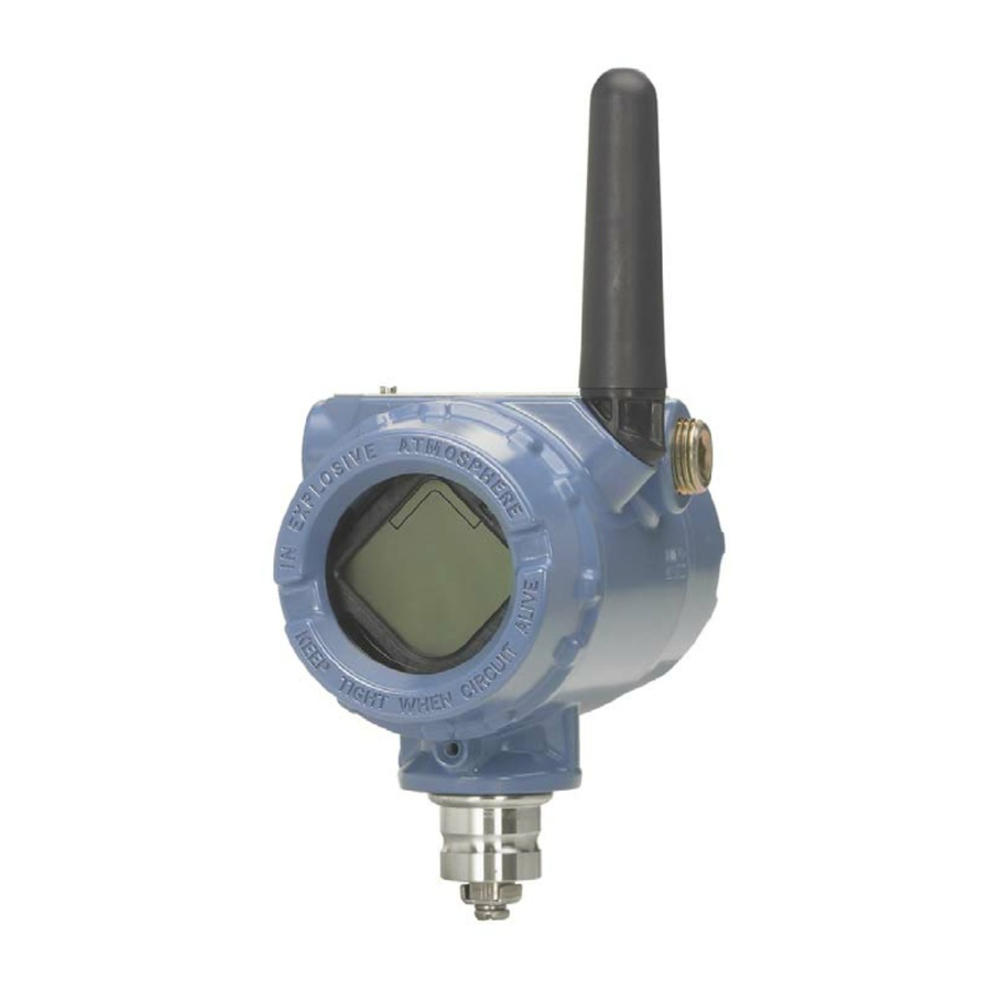
Rosemount 702 Wireless Discrete Transmitter
www.rosemount.com
¢00825-0100-4648[¤
Step 1: Physical Installation
Step 2: Verify Operation
Step 3: Reference Information
Product Certifications
EC Declaration of Conformity
Start
End
Rosemount 702
Advertisement
Table of Contents

Related Manuals for Emerson Rosemount 702


Summary of Contents for Emerson Rosemount 702
- Page 1 Quick Installation Guide 00825-0100-4702, Rev BA Rosemount 702 August 2009 Rosemount 702 Wireless Discrete Transmitter Start Step 1: Physical Installation Step 2: Verify Operation Step 3: Reference Information Product Certifications EC Declaration of Conformity www.rosemount.com ¢00825-0100-4648[¤...
-
Page 2: Important Notice
IMPORTANT NOTICE The Rosemount 702 and all other wireless devices should be installed only after the 1420 Wireless Gateway has been installed and is functioning properly. Wireless devices should also be powered up in order of proximity from the 1420 Wireless Gateway, beginning with... - Page 3 Quick Installation Guide 00825-0100-4702, Rev BA Rosemount 702 August 2009 IMPORTANT NOTICE Shipping considerations for wireless products (Lithium Batteries): The unit was shipped to you without the battery installed. Please remove the battery pack prior to shipping the unit. Primary lithium batteries are regulated in transportation by the U.S. Department of...
-
Page 4: Step 1: Physical Installation
HYSICAL NSTALLATION The Rosemount 702 and all other wireless devices should be installed only after the 1420 Wireless Gateway has been installed and is functioning properly. Wireless devices should also be powered up in order of proximity from the 1420 Wireless Gateway, beginning with the closest. -
Page 5: Remote Mount
Quick Installation Guide 00825-0100-4702, Rev BA Rosemount 702 August 2009 CONTINUED Remote Mount 1. Install the switch according to standard installation practices. Be sure to use thread sealant on all connections. 2. Run wiring (and conduit if necessary) from the switch to the 702. -
Page 6: Step 2: Verify Operation
During normal operation, the LCD should display the PV value at the update rate up to 1 minute intervals. Refer to the Rosemount 702 Manual for error codes and other LCD messages. Press the Diagnostic button to display the TAG, Device ID, Network ID, Network Join Status and Device Status screens. - Page 7 If the device joins the network and immediately has an alarm present, it is likely due to sensor configuration. Check the sensor wiring (see Rosemount 702 Terminal Diagram on page 9) and the sensor configuration (see 702 Fast Key Sequence on page 9).
-
Page 8: Troubleshooting
Quick Installation Guide 00825-0100-4702, Rev BA Rosemount 702 August 2009 Troubleshooting If the device is not operating properly, refer to the troubleshooting section of the manual. The most common cause of incorrect operation is the Network ID and Join Key. The Network ID and Join Key in the device must match that of the 1420 Wireless Gateway. -
Page 9: Reference Information
Rosemount 702 August 2009 3: R EFERENCE NFORMATION Figure 3. Rosemount 702 Terminal Diagram NOTE: In order to communicate with a 375 Field Communicator, the device must be powered by connecting the battery pack. Table 1. 702 Fast Key Sequence... -
Page 10: Product Certifications
RF spectrum. Nearly every country requires this type of product certification. Emerson is working with governmental agencies around the world to supply fully compliant products and remove the risk of violating country directives or laws governing wireless device usage. - Page 11 Quick Installation Guide 00825-0100-4702, Rev BA Rosemount 702 August 2009 Hazardous Locations Certificates North American Certifications Factory Mutual (FM) Approvals I5 FM Intrinsically Safe, Non-Incendive and Dust Ignition-Proof Intrinsically Safe for Class I/II/III, Division 1, Groups A, B, C, D, E, F, and G.
- Page 12 Quick Installation Guide 00825-0100-4702, Rev BA Rosemount 702 August 2009 IECEx Certifications I7 IECEx Intrinsic Safety Certificate No.: IECExBAS07.0082X Ex ia IIC T4 (-60 °C <= T <= 70 °C), Ex ia IIC T5 (-60 °C <= T <= 40 °C)
- Page 13 Quick Installation Guide 00825-0100-4702, Rev BA Rosemount 702 August 2009 3. The cable entry of transmitter should be protected to ensure the degree of protection of the enclosure IP 20 (GB4208-1993) at least. 4. The cables between transmitter and associated apparatus should be shielded cables (the cables must have insulated shield).
-
Page 14: Ec Declaration Of Conformity
Quick Installation Guide 00825-0100-4702, Rev BA Rosemount 702 August 2009 Figure 6. EC Declaration of Conformity for Rosemount 702 EC Declaration of Conformity No: RMD 1066 Rev. B Rosemount Inc. 8200 Market Boulevard Chanhassen, MN 55317-9685 declare under our sole responsibility that the product,... - Page 15 Quick Installation Guide 00825-0100-4702, Rev BA Rosemount 702 August 2009 Schedule No: RMD 1066 Rev. B EMC Directive (2004/108/EC) All Models with ”Operating Frequency and Protocol Code 1” EN 61326-1:1997 with amendments A1, A2, and A3 All Models with ”Operating Frequency and Protocol Code 3”...
- Page 16 Quick Installation Guide 00825-0100-4702, Rev BA Rosemount 702 August 2009 Schedule No: RMD 1066 Rev. B ATEX Directive (94/9/EC) Model 702 Wireless Temperature Transmitter Certificate: Baseefa07ATEX0239 Intrinsically Safe - Equipment Group II, Category 1 G Ex ia IIC T4(-60°C ” Ta ” +70°C) Harmonized Standards Used: EN60079-0: 2006;...
Need help?
Do you have a question about the Rosemount 702 and is the answer not in the manual?
Questions and answers