Emerson Rosemount 702 Reference Manual
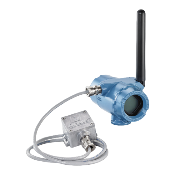
Wireless discrete transmitter for plunger arrival
Hide thumbs
Also See for Rosemount 702:
- Reference manual (142 pages) ,
- Quick start manual (60 pages) ,
- Quick installation manual (17 pages)

Related Manuals for Emerson Rosemount 702


Summary of Contents for Emerson Rosemount 702
- Page 1 Reference Manual 00809-0400-4702, Rev AA June 2018 ™ Rosemount 702 Wireless Discrete Transmitter for plunger arrival...
- Page 2 Rosemount 702 Wireless Discrete Transmitter for plunger arrival NOTICE Read this manual before working with the product. For personal and system safety, and for optimum product performance, make sure to thoroughly understand the contents before installing, using, or maintaining this product.
- Page 3 CAUTION! Shipping considerations for wireless products. • The unit was shipped to you without the power module installed. Remove the power module prior to shipping. • Each Black Power Module contains two “C” size primary lithium-thionyl chloride battery. Primary lithium batteries are regulated in transportation by the U.
-
Page 5: Table Of Contents
Contents Contents Chapter 1 Introduction ........................1 Using the manual ........................... 1 Product recycling/disposal ......................2 Chapter 2 Configuration ........................3 Safety messages ..........................3 Benchtop Configuration ......................... 4 2.2.1 Device Network Configuration ..................4 2.2.2 Entering Network ID and Join Key Via AMS TREX .............. 5 2.2.3 Entering the network and join key via AMS ...............9 2.2.4... - Page 6 Contents Power module replacement ......................64 Resetting counts .......................... 64 Service support ..........................66 Chapter 7 Diagnostics and troubleshooting ..................69 Safety messages ...........................69 Troubleshooting .......................... 70 Chapter 8 Appendix A ........................75 Product Certifications ........................75 Ordering Information, Specifications, and Dimensional Drawings ..........75 Chapter 9 Appendix B specifications and reference data ..............
-
Page 7: Chapter 1 Introduction
This manual provides information on installing, operating, and maintaining the ™ Rosemount 702 Wireless Discrete Transmitter for plunger arrival detection. The table below lists the different variants of the Rosemount 702 transmitter; refer to the table if looking for documentation on different variants: Model Number Functionality... -
Page 8: Product Recycling/Disposal
Introduction Figure 1-1: 702 Plunger Arrival Sensor A. Plunger arrival sensor (ETC Cyclops) G. Lower lubricator outlet B. 702 plunger arrival H. Production gas C. Lubricator I. Well casing D. Plunger J. Well casing/production tube E. Wastewater K. Well casing F. -
Page 9: Chapter 2 Configuration
Configuration Configuration Safety messages Instructions and procedures in this section may require special precautions to ensure the safety of the personnel performing the operations. Information that potentially raises safety issues is indicated by a warning symbol ( ). Refer to the following safety messages before performing an operation preceded by this symbol. -
Page 10: Benchtop Configuration
Remove the power module-side housing cover to expose the terminal block and HART communication terminals, then connect the power module to power the unit for configuration. The Rosemount 702 Transmitter is compatible with industry standard HART configuration ™ ™ tools such as the Emerson... -
Page 11: Entering Network Id And Join Key Via Ams Trex
Configuration 2.2.2 Entering Network ID and Join Key Via AMS TREX Take the following steps to enter the network ID and join key via TREX. The Overview screen shows at startup. From the Overview screen, navigate to the Configure screen. Enter the network ID. - Page 12 Configuration Enter the Key 1 join key. Enter the Key 2 join key. 702 Wireless Discrete Transmitter...
- Page 13 Configuration Enter the Key 3 join key. Enter the Key 4 join key. Reference Manual...
- Page 14 Configuration Select the Yes - Attempt to Join Now button. The validation screen displays. 702 Wireless Discrete Transmitter...
-
Page 15: Entering The Network And Join Key Via Ams
Configuration 2.2.3 Entering the network and join key via AMS Take the following steps to enter the network ID and join key via AMS. From the AMS Overview screen, select the Join Device to Network tab. The Join Device to Network screen opens. Enter all four key fields and select Next to complete. -
Page 16: Field Communicator Bench Configuration
Field Communicator Bench Configuration All of the below references and screenshots associated with Field Communicator is using the Emerson AMS TREX. Similar screens are present in other versions of field communicators; refer to the manual for your handheld communicator device for more information. - Page 17 Configuration On the Configure screen, select Guided Setup. Note Alternatively, Manual Setup can be selected to verify or change all configuration settings including option and advanced settings. Select Basic Setup. Reference Manual...
- Page 18 Configuration Enter a Long Tag. When completed, select OK. Enter a Tag. When completed, select OK. 702 Wireless Discrete Transmitter...
- Page 19 Configuration Enter a Descriptor. When completed, select OK. Enter a Message.When completed, select OK. Reference Manual...
- Page 20 Configuration Enter a Date. When completed, select OK. When finished, select Send to implement configuration changes. Basic Setup "Operation completed successfully" screen appears. 702 Wireless Discrete Transmitter...
-
Page 21: Latching Configuration
Configuration When configuration is completed, remove the HART communication leads from the COMM terminals on the terminal block and replace the rear housing cover. 2.2.5 Latching configuration To configure Latching with AMS TREX, take the following steps. At startup, the Overview screen displays. From the Overview screen, select Configure. - Page 22 Configuration Enter the duration the plunger state should be latched active after detected. Operation completed successfully message displays when completed. 702 Wireless Discrete Transmitter...
-
Page 23: Ams Wireless Configurator Bench Configuration
Configuration 2.2.6 AMS Wireless Configurator Bench Configuration AMS Wireless Configurator can connect to devices directly, using a HART modem, or through a Wireless Gateway. Guided Setup Select Guided Setup to verify or change initial configuration settings. Open the AMS Intelligent Device Manager from Windows as shown. The Overview screen displays. - Page 24 Configuration Select the Service Tools tab. The Basic Setup screen opens. Enter the Long tag. When done, select Next. 702 Wireless Discrete Transmitter...
- Page 25 Configuration Enter the duration the plunger state should be latched active after detected. When done, select Next. Select a device display option. When done, select Next. Reference Manual...
- Page 26 Configuration Choose which device variable to show on the device display, then select Next. When finished, select Send to implement configuration changes.The Guided Setup is complete. Manual Setup Select Manual Setup to verify or change all configuration settings, including advanced, optional settings.
- Page 27 Configuration Setup Current State for Channels. When done, select Send. Select the Display Mode. When done, select Send. Reference Manual...
- Page 28 Configuration Select appropriate settings in the Variable Mapping, Data Collection, and Communications Settings fields. When done, select Send. Select appropriate settings in the Write Protection, HART Lock, and Radio Upgrade fields. When done, select Send. 702 Wireless Discrete Transmitter...
- Page 29 Configuration Select appropriate settings in the Electronics Temperature fields, beginning with the Setup field. When done, select Send. Add the Long Tag, Tag, and Descriptors in the Indentification fields. When done, select Send. Reference Manual...
-
Page 30: Hart Menu Tree
Configuration HART menu tree For ease of operation, changing setup, such as switch type, can be completed in several locations. 702 Wireless Discrete Transmitter... - Page 31 Configuration Reference Manual...
- Page 32 Configuration 702 Wireless Discrete Transmitter...
- Page 33 Configuration Reference Manual...
- Page 34 Configuration 702 Wireless Discrete Transmitter...
-
Page 35: Detailed Configuration
Configuration Detailed Configuration Configuring Latching Period The Rosemount 702 for plunger arrival includes the ability to latch plunger arrival events for a configurable duration. See figures below for an example of the latching period. Figure 2-2: Short Latch Time Events... -
Page 36: Advanced Burst Configuration
Configuration The start of latch hold timer will begin when the measure signal first transitions to active state. Figure 2-3: Latch Hold Timer A: Measured B: Reported Note The default for the plunger arrival option will be to latch high. This is what is required to function with the ETC cyclops arrival sensor. -
Page 37: Advanced Discrete Inversion
Configuration Figure 2-4: Burst Commands 2.4.2 Advanced discrete inversion To set the discrete inversion (advanced), count roll over, reported value, and fault state: Go to manual setup, select discrete channels, select Setup Channel. Reference Manual... - Page 38 Configuration Figure 2-5: Discrete Inversion A table of the Reported values is shown below for reference. Plunger arrival application types Table 2-1: Reported Values Reported Value Value Name Analog Value Discrete Value Plunger Plunger Plunger Plunger Plunger Plunger Event Not Event De- Event Not Event De-...
-
Page 39: Configure Lcd
Configuration Table 2-1: Reported Values (continued) Reported Value Value Name Analog Value Discrete Value Cold/Hot Cold 16.000 15.000 Dry/Wet 32.000 33.000 Absent/ Absent Present 45.000 44.000 Present 2.4.3 Configure LCD Select the Display tab to configure Display Modes, Display Options. Figure 2-6: Configure LCD display 2.4.4... -
Page 40: Configure Security
Configuration Figure 2-7: Configure Variable Reporting 2.4.5 Configure Security To figure Write Protection and Otap block out, select the Security tab and access the dropdown menus to populate the fields. Figure 2-8: Configure Security. 702 Wireless Discrete Transmitter... -
Page 41: Configure Temperature Units
Configuration 2.4.6 Configure temperature units Select the Device Temperature tab to setup temperature. Use the dropdown menu to populate the field. Figure 2-9: Configure Device Temperature 2.4.7 Configure the device tagging Select the Device Information tab to configure the Tag and Identification fields. Reference Manual... -
Page 42: Removing The Power Module
Configuration Figure 2-10: Configure Device Identification Removing the Power Module After the device and the network have been configured, remove the power module and replace the rear housing cover. Insert the power module only when the device is ready for commissioning. -
Page 43: Chapter 3 Installation
Installation Installation Safety messages Instructions and procedures in this section may require special precautions to ensure the safety of the personnel performing the operations. Information that potentially raises safety issues is indicated by a warning symbol ( ). Refer to the following safety messages before performing an operation preceded by this symbol. -
Page 44: Physical Installation
Installation Physical installation Choosing an installation location and position When choosing an installation location and position, consider access to the Rosemount 702 Transmitter for ease of power module replacement. For best performance, the antenna should be vertical with space between objects in a parallel metal plane, such as a pipe or metal framework, as the pipes or framework may adversely affect the antenna’s performance. -
Page 45: Electrical Installation
Wiring the arrival sensor The Rosemount 702 Transmitter has screw terminals corresponding to each of the plunger arrival sensor’s wiring terminals. These terminals are labeled as follows:... - Page 46 Installation Figure 3-2: Wiring the Arrival Sensor Rosemount 702 Transmitter ETC Cyclops Sensor A. PWR OUT A. PWR B. SIG B. SIG C. COM C. COM Grounding Grounding of the electronics enclosure should be done in accordance with local/national installation codes and with facility recommended wiring practices. Grounding is accomplished by using the external case grounding terminal.
- Page 47 Installation Figure 3-3: Grounding screw location A. Grounding screw location Grounding of the sensor shield wire is accomplished by using the internal case grounding screw inside the terminal side cover. There is one grounding screw connection provided, located inside the housing, see Figure 3-xx. The ground screw is identified by a ground symbol .
- Page 48 Installation 702 Wireless Discrete Transmitter...
-
Page 49: Commisioning And Verification
Commisioning and verification Commisioning and verification Safety messages Instructions and procedures in this section may require special precautions to ensure the safety of the personnel performing the operations. Information that potentially raises safety issues is indicated by a warning symbol ( ). Refer to the following safety messages before performing an operation preceded by this symbol. -
Page 50: Wireless Connectivity And Power Module
Install the Black Power Module, SmartPower Solutions model number 701PBK into the Rosemount 702 Transmitter to power the device. Wireless devices should be powered up in order of proximity from the Gateway, beginning with the closest device, then working outward from the Gateway. This results in a simpler and faster network installation. - Page 51 Commisioning and verification View the following communications information: • Communication status: displays whether the device is or is not connected to the wireless network. • Join Mode: Displays the current join mode. Select Join Mode to change the way that the device joins the wireless network. Attempt to join immediately on powerup or reset is the default option.
-
Page 52: Verify Communication Using Ams Wireless Configurator
Commisioning and verification • Neighbor Count: Displays the number of available neighboring devices. • Advertisement Count: Displays the number of advertisement packets received. When finished, select Back to return to the Communications screen. 4.2.2 Verify Communication using AMS Wireless Configurator Open the AMS Wireless Configurator. -
Page 53: Verify Communication Using Wireless Gateway
Commisioning and verification 4.2.3 Verify communication using Wireless Gateway Open the Wireless Gateway web interface. This page shows whether the device has joined the network and is communicating properly. Figure 4-2. Wireless Gateway Home Page Reference Manual... -
Page 54: Change The Network Id And Join Key
Commisioning and verification Change the network ID and join key Using the field communicator to change the Network ID and Join Key If the Network ID and Join Key need to be changed, refer to “Joining a wireless network using Field Communicator” in Guided Setup for the Field Communicator. -
Page 55: Chapter 5 Operation
Operation Operation Safety messaages Instructions and procedures in this section may require special precautions to ensure the safety of the personnel performing the operations. Information that potentially raises safety issues is indicated by a warning symbol ( ). Refer to the following safety messages before performing an operation preceded by this symbol. -
Page 56: Defining Channel Descriptions
Latching feature The Rosemount 702 has a latching feature that, when enabled, allows detection of momentary state changes to be held for a configurable latch period. The latching feature can be configured to detect either high or low state changes. By default, the Plunger state (channel 1) is enabled to latch high state changes for a period of one minute. - Page 57 Operation Figure 5-1: Latch Time Short Events Measured Reported The start of the latch hold timer begins when the measured signal first transitions to active state. Figure 5-2: Latch Hold Time Start Measured Reported The latch only applies to transitions into the active state. As soon as the reported value is no longer latched,the devices is armed for the next event.
-
Page 58: Interpreting Lcd Display
Operation Interpreting LCD display Procedure All Segments On: used to visually determine if there are any bad segments on the LCD display. Device Identification: used to determine Device Type. Device Information - Tag: user entered tag which is eight characters long - will not display if all characters are blank. - Page 59 Operation SV Screen – Power Savings (Channel 2). Electronics Temperature. Supply Voltage. Channel 1 Count of close/open cycles. Reference Manual...
-
Page 60: Diagnostic Button Screen Sequence
Operation Channel 2 Count of close/open cycles. 5.4.1 Diagnostic button screen sequence The following five screens will display when the device is operating properly and the Diagnostic Button has been pressed and held for longer than two seconds. Procedure Diagnostic Button Screen 1: Tag - user entered tag which is eight characters long - will not display if all characters are blank. - Page 61 Operation Diagnostic Button Screen 3: Network ID Diagnostic Button Screen 4.9: the device has joined a network and has been fully configured and has multiple parents. 5. Diagnostic Button Screen 5: voltage reading at the power module terminals. Reference Manual...
-
Page 62: Network Connection Status Screens
Operation 5.4.2 Network connection status screens One of the following network diagnostic status screens will display in the fourth position of the Diagnostic Button Screen sequence. The screen displayed is dependent on the progress of the device in joining the wireless network Procedure Diagnostic Button Screen 4.1: the device is attempting to start the radio. - Page 63 Operation Diagnostic Button Screen 4.5: the device is searching for the Network. Diagnostic Button Screen 4.6: the device is attempting to join a network. Diagnostic Button Screen 4.7: the device is connected to the Network, but is in a “Quarantined” state. Reference Manual...
-
Page 64: Device Diagnostic Screens
Operation Diagnostic Button Screen 4.8: the device is joined and operational, but is running with limited bandwidth for sending periodic data Diagnostic Button Screen 4.9: the device has joined a network and has been fully configured and has multiple parents. 5.4.3 Device diagnostic screens The following screens will show the device diagnostics depending on the state of the... - Page 65 Operation Diagnostic Button Screen 6.2: There is a warning which should be addressed, but should not affect the device output. Diagnostic Button Screen 7.1: the terminal voltage has dropped below level of operating limit. Replace the Black Power Module model number 701PBKKF (Part Number: 00753-9220-0001).
- Page 66 Operation Diagnostic Button Screen 8: the device cannot retrieve information from the radio in the device - the device may still be operational and publishing HART data. Diagnostic Button Screen 9: configuration of the transmitter is invalid such that critical operation of the device may be affected - check the extended configuration status to identify which configuration item(s) need to be corrected.
- Page 67 Operation Diagnostic Button Screen 11: The device has not yet received all of the requested wireless bandwidth needed to operate as configured. Diagnostic Button Screen 12: One or more output channels are being driven to a fault state. Diagnostic Button Screens 13 +: All of the periodic screens except supply voltage will now be displayed to conclude the Diagnostic Button Screen Sequence.
-
Page 68: Modbus And Opc Mapping
Following is a table of parameters that can be used for Modbus and OPC mapping. These parameters are used by the Emerson Wireless Gateway and can be found in the web interface of the gateway. some of these parameters are analog values and some are discrete, and this is noted in the description. -
Page 69: Chapter 6 Maintenance
Maintenance Maintenance Safety messages Instructions and procedures in this section may require special precautions to ensure the safety of the personnel performing the operations. Information that potentially raises safety issues is indicated by a warning symbol ( ). Refer to the following safety messages before performing an operation preceded by this symbol. -
Page 70: Power Module Replacement
Maintenance Power module replacement Expected power module life is 10 years at reference conditions. When the power module needs to be replaced, remove the power module cover and the depleted power module. Replace the power module with a new Black Power Module, ™... - Page 71 Maintenance Select “Maintenance” tab and then select “Reset/Restore.” Use the “Reset Channel 1” button to restore the counts back to 0. See the Example for AMS below: Reference Manual...
-
Page 72: Service Support
Maintenance Service support To expedite the return process outside of the United States, contact the nearest Emerson representative. Within the United States, call the Emerson Instrument and Valve Response Center using the 1-800-654-RSMT (7768) toll-free number. This center, available 24 hours a day, will assist you with any needed information or materials. - Page 73 Maintenance NOTICE Shipping considerations for wireless products. • The unit was shipped to you without the Power Module installed. Please remove the Power Module prior to shipping the unit. • Each Power Module contains two "C" size primary lithium/thionyl chloride batteries. Primary lithium batteries (charged or discharged) are regulated during transportation by the U.S.
- Page 74 Maintenance 702 Wireless Discrete Transmitter...
-
Page 75: Diagnostics And Troubleshooting
Diagnostics and troubleshooting Diagnostics and troubleshooting Safety messages Instructions and procedures in this section may require special precautions to ensure the safety of the personnel performing the operations. Information that potentially raises safety issues is indicated by a warning symbol ( ). Refer to the following safety messages before performing an operation preceded by this symbol. -
Page 76: Troubleshooting
Diagnostics and troubleshooting Troubleshooting Wireless Verify that you are using the 702DX52 option transmitter and not another option; if so, verify the channel 2 state is “off” or “False.” If the device is not joined to the network after power up, verify the correct configuration of the Network ID and Join Key, and verify Active advertising has been enabled on the Wireless Gateway. - Page 77 Diagnostics and troubleshooting Table 7-1: Diagnostics (continued) Recommended Ac- Associated Device Device Status State the Problem tions Status Bits Output Failure The discrete output has 1. Check the discrete Byte 3; bit 7 not reached its inten- circuit wiring, connec- ded output state.
- Page 78 Diagnostics and troubleshooting Table 7-1: Diagnostics (continued) Recommended Ac- Associated Device Device Status State the Problem tions Status Bits Electronic Warning The device has detec- 1. Confirm and correct Byte 0; bit 4 Byte 0; bit ted an electronics error all configuration pa- that does not currently rameters.
- Page 79 Diagnostics and troubleshooting Table 7-1: Diagnostics (continued) Recommended Ac- Associated Device Device Status State the Problem tions Status Bits Database Storage The device has failed to 1. Reset the device. 2. Byte 0; bit 2 Warning write to the database If logging dynamic da- memory.
- Page 80 Diagnostics and troubleshooting 702 Wireless Discrete Transmitter...
-
Page 81: Chapter 8
Select the appropriate Quick Start Guide. Ordering Information, Specifications, and Dimensional Drawings To view current Rosemount 702 Ordering Information, Specifications, and Dimensional Drawings, follow these steps: Go to Emerson.com/Rosemount/702. Scroll as needed to the green menu bar and click Documents & Drawings. - Page 82 Appendix A 702 Wireless Discrete Transmitter...
-
Page 83: Appendix B Specifications And Reference Data
Appendix B specifications and reference data Appendix B specifications and reference data Functional specifications 9.1.1 Discrete input Single or dual SPST dry contacts, single SPDT dry contacts or leak detection. To maintain I.S. ratings, contacts must be limited to simple switches or leak detection only. A.1.3 Switching threshold, models 702DX32, 702DX42 •... -
Page 84: Humidity Limits
• Cover O-ring - Buna-N 9.2.3 Terminal block connections The Rosemount 702 has a pair of screw terminals for each of two channels, and a pair of communication terminals. These terminals are labeled as follows: • CH1+: Channel one positive... -
Page 85: Antenna
Appendix B specifications and reference data • CMN: Common • CH2+: Channel two positive • CMN: Common • COMM: Communication terminals 9.2.4 Antenna • PBT/PC integrated omnidirectional antenna 9.2.5 Conduit entries ½–14 NPT 9.2.6 Enclosure ratings (702) ® NEMA 4X and IP66/67 9.2.7 Mounting Transmitters may be attached directly to switch, brackets also permit remote mounting. -
Page 86: Vibration Effect
Appendix B specifications and reference data 9.3.2 Vibration effect Wireless output unaffected when tested per the requirements of IEC60770-1 field or pipeline with high vibration level (10–60 Hz 0.21 mm displacement peak amplitude/ 60–2000 Hz 3 g). Wireless output unaffected when tested per the requirements of IEC60770-1 field with general application or pipeline with low vibration level (10–60 Hz 0.15 mm displacement peak amplitude/60–500 Hz 2 g). - Page 87 Appendix B specifications and reference data • Meets MIL-STD-810G (method 510.5, procedure I and II) Physical specifications Weight: 1.0 lb (0.4 kg) RF lightning arrestor In-line lightning arrestor Electrical connection: lightning arrestor MUST be grounded per local electrical codes and regulations.
-
Page 88: Dimensional Drawings
Appendix B specifications and reference data Dimensional drawings Figure 9-1: Device Connection and RF Lightning Arrestor 2.75 4 PLS 20.2-in. [0.513m] A. Antenna B. Mounting bracket C. Mounting arrester D. 25 th (7.5 m) cable E. Min drip loop Ø12-in. (0.3 m) Installing the high gain remote antenna Mount the transmitter following best practice mounting procedures as outlined in the Quick Start Guide and Manual. - Page 89 Appendix B specifications and reference data Figure 9-2: RF Lightning Protector Connect antenna to mounting bracket and tighten nut carefully. Figure 9-3: Connect Antenna to Mounting Bracket Reference Manual...
- Page 90 Appendix B specifications and reference data Unwind coaxial cable and connect the cable to both the antenna and the lightning protector connected to the transmitter, leaving one loop minimum for a drip loop. Ensure the drip loop is lower than the device, allowing water to flow away from the device.
- Page 91 Appendix B specifications and reference data Figure 9-5: Apply Coaxial Sealant Attach U-bolts to mounting bracket in correct orientation ensuring that antenna will be positioned in a vertical position. Reference Manual...
- Page 92 Appendix B specifications and reference data Figure 9-6: Attach U-bolts Tighten U-bolts to mast and ensure that antenna is pointed in a vertical direction. 702 Wireless Discrete Transmitter...
- Page 93 Appendix B specifications and reference data Figure 9-7: Tighten U-bolts Reference Manual...
- Page 94 Appendix B specifications and reference data 702 Wireless Discrete Transmitter...
- Page 95 Appendix B specifications and reference data Reference Manual...
- Page 96 Twitter.com/Rosemount_News © 2018 Emerson. All rights reserved. Facebook.com/Rosemount Emerson Terms and Conditions of Sale are available upon request. The Emerson logo is a Youtube.com/user/RosemountMeasurement trademark and service mark of Emerson Electric Co. Rosemount is mark of one of the Google.com/+RosemountMeasurement...
Need help?
Do you have a question about the Rosemount 702 and is the answer not in the manual?
Questions and answers