Emerson Rosemount 2051 Reference Manual
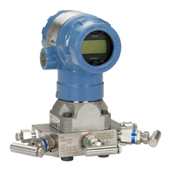
Pressure transmitter with hart revision 5 and 7 selectable protocol
Hide thumbs
Also See for Rosemount 2051:
- Reference manual (200 pages) ,
- Quick start manual (48 pages) ,
- Quick installation manual (25 pages)

Related Manuals for Emerson Rosemount 2051


Summary of Contents for Emerson Rosemount 2051
- Page 1 Reference Manual 00809-0100-4107, Rev BA April 2013 Rosemount 2051 Pressure Transmitter ® with HART Revision 5 and 7 Selectable Protocol www.rosemount.com...
- Page 3 Equipment service needs. 1-800-654-7768 (24 hours—includes Canada) Outside of these areas, contact your local Emerson Process Management representative. The products described in this document are NOT designed for nuclear-qualified applications. Using non-nuclear qualified products in applications that require nuclear-qualified hardware or products may cause inaccurate readings.
-
Page 5: Table Of Contents
Reference Manual Table of Contents 00809-0100-4107, Rev BA April 2013 Contents 1Section 1: Introduction Using this manual............1 Models covered . - Page 6 Table of Contents Reference Manual April 2013 00809-0100-4107, Rev BA 2.8.2 Configuring Scaled Variable ........22 2.8.3 Re-Mapping device variables .
- Page 7 Reference Manual Table of Contents 00809-0100-4107, Rev BA April 2013 4.4.3 Configuration Button lock.........56 4.4.4 Local Operator Interface Password .
- Page 8 Safety Instrumented Systems (SIS) Certification ......93 7.1.1 Rosemount 2051 safety certified identification ..... .93 7.1.2 Installation in SIS applications .
- Page 9 Reference Manual Table of Contents 00809-0100-4107, Rev BA April 2013 A.2.1 Service............103 A.2.2 Range and sensor limits.
- Page 10 Table of Contents Reference Manual April 2013 00809-0100-4107, Rev BA B.4.1 Hazardous Locations Certifications ....... 175 Approval drawings .
-
Page 11: Using This Manual
Product recycling/ disposal ..........page 6 Using this manual The sections in this manual provide information on installing, operating, and maintaining the Rosemount 2051. The sections are organized as follows: Section 2: Configuration provides instruction on commissioning and operating Rosemount 2051 Transmitters. -
Page 12: Models Covered
Reference Manual Section 1: Introduction 00809-0100-4107, Rev BA April 2013 Models covered The following Rosemount 2051 Pressure Transmitters are covered by this manual: ™ 1.2.1 Rosemount 2051C Coplanar Pressure Transmitter Measures differential and gage pressure up to 2000 psi (137,9 bar). -
Page 13: Hart Installation Flowchart
Reference Manual Section 1: Introduction 00809-0100-4107, Rev BA April 2013 HART installation flowchart Figure 1-1. HART installation flowchart START HERE Bench Calibration? Field Install Configure Security and Alarm Configure for Configure for Configure for page 59 Verify Pressure Level Flow Mount Transmitter page 40... -
Page 14: Transmitter Overview
The basic block diagram of the Rosemount 2051CD is illustrated in Figure 1-3 on page For the Rosemount 2051, pressure is applied to the isolating diaphragm(s). The oil deflects the sensor which then changes its capacitance or voltage signal. This signal is then changed to a digital signal by the Signal Processing. -
Page 15: Service Support
Authorization (RMA) number. The center will also ask for the process material to which the product was last exposed. For inquiries outside of the United States, contact the nearest Emerson Process Management representative for RMA instructions. To expedite the return process outside of the United States, contact the nearest Emerson Process Management representative. Introduction... -
Page 16: Product Recycling/ Disposal
Material Safety Data Sheet (MSDS) for each substance must be included with the returned goods. Emerson Process Management Instrument and Valve Response Center representatives will explain the additional information and procedures necessary to return goods exposed to hazardous substances. -
Page 17: Configuration Overview
Reference Manual Section 2: Configure 00809-0100-4107, Rev BA April 2013 Section 2 Configuration Configuration overview ............page 7 Safety messages . -
Page 18: System Readiness
Verify the latest Device Driver (DD/DTM) is loaded on your systems to ensure proper communi- cations. Download the latest DD at www.emersonprocess.com or www.hartcomm.org. 2. In the Browse by Member dropdown menu, select Rosemount business unit of Emerson Process Management. 3. Select desired Product... -
Page 19: Configuration Basics
Set all transmitter hardware adjustments during commissioning to avoid exposing the transmitter electronics to the plant environment after installation. The Rosemount 2051 can be configured either before or after installation. Configuring the transmitter on the bench using either a Field Communicator, AMS Device Manager, or Local Operator Interface (LOI) ensures all transmitter components are in working order prior to installation. -
Page 20: Configuration Tools
Reference Manual Section 2: Configure 00809-0100-4107, Rev BA April 2013 Figure 2-1. Wiring the Transmitter (4-20 mA HART) A. Vdc supply 250 (necessary for HART communication only) B. R 2.4.2 Configuration tools Figure 2-2. Wiring the Transmitter (1-5 Vdc Low Power) A. - Page 21 Reference Manual Section 2: Configure 00809-0100-4107, Rev BA April 2013 Figure 2-3. Device Dashboard 2051 FT 45B Online 1. Overview 2. Configure 3. Service Tools SAVE Configuring with AMS Device Manager Full configuration capability with AMS Device Manager requires loading the most current Device Descriptor (DD) for this device.
-
Page 22: Setting The Loop To Manual
A Full list of configuration parameters that can be reviewed and configured using a Field Communicator are located in Appendix C: Field Communicator Menu Trees and Fast Keys Fast key sequences for the latest DD are shown in Table 2-3. For fast key sequences for legacy DD's contact your local Emerson Process Representative. Configuration... -
Page 23: Verifying Configuration With Ams Device Manager
Reference Manual Section 2: Configure 00809-0100-4107, Rev BA April 2013 Table 2-3. Rosemount 2051 Device Dashboard fast key sequence From the HOME screen, enter the fast key sequences listed Fast Key Sequence Function HART 7 HART 5 Alarm and Saturation Levels... -
Page 24: Basic Setup Of The Transmitter
EXIT MENU TORR 2.6.2 Setting transmitter output (Transfer Function) The Rosemount 2051 has two output settings: Linear and Square Root. As shown in Figure 2-7 on page 16, activating the square root options makes analog output proportional to flow, and includes a fixed Low Flow Cutoff at 5%. - Page 25 Reference Manual Section 2: Configure 00809-0100-4107, Rev BA April 2013 Setting transmitter output with a Field Communicator From the HOME screen, enter the fast key sequence 2, 2, 1, 1, 6 Device Dashboard Fast Keys Setting transmitter output with AMS Device Manager Right click on the device and select Configure.
-
Page 26: Rerange The Transmitter
Reference Manual Section 2: Configure 00809-0100-4107, Rev BA April 2013 Figure 2-7. 4-20 mA HART square root output transition point 20mA % Pressure Input % Pressure Input A. Square Root Curve B. 5% Transition Point C. 4% Transition Point 2.6.3 Rerange the transmitter The Range Values command sets each of the lower and upper range analog values (4 and 20 mA/1-5 Vdc points) to a pressure. - Page 27 Reference Manual Section 2: Configure 00809-0100-4107, Rev BA April 2013 Entering range points with a Local Operator Interface Reference Figure 2-8 on page 17 to rerange the transmitter using the Local Operator Interface. Enter values using SCROLL and ENTER buttons. Figure 2-8.
- Page 28 Regardless of the range points, the Rosemount 2051 will measure and report all readings within the digital limits of the sensor. For example, if the 4 and 20 mA(1-5 Vdc)
-
Page 29: Damping
Reference Manual Section 2: Configure 00809-0100-4107, Rev BA April 2013 2.6.4 Damping The damping command changes the response time of the transmitter; higher values can smooth variations in output readings caused by rapid input changes. Determine the appropriate damping setting based on the necessary response time, signal stability, and other requirements of the loop dynamics within your system. -
Page 30: Configuring The Lcd Display
Reference Manual Section 2: Configure 00809-0100-4107, Rev BA April 2013 Configuring the LCD Display The LCD Display configuration command allows customization of the LCD to suit application requirements. The LCD will alternate between the selected items. Pressure Units Sensor Temperature ... -
Page 31: Detailed Transmitter Setup
If the pressure goes outside the sensor limits, or if the output would be beyond the saturation points, the output will be limited to the associated saturation point. The Rosemount 2051 transmitter automatically and continuously performs self-diagnostic routines. If the self-diagnostic routines detect a failure, the transmitter drives the output to configured alarm and value based on the position of the alarm switch. -
Page 32: Configuring Scaled Variable
Reference Manual Section 2: Configure 00809-0100-4107, Rev BA April 2013 Note Transmitters set to HART multidrop mode send all saturation and alarm information digitally; saturation and alarm conditions will not affect the analog output. See also “Establishing multidrop communication” on page Configuring Alarm and Saturation Levels using a Field Communicator From the HOME screen, enter the fast key sequence... - Page 33 Reference Manual Section 2: Configure 00809-0100-4107, Rev BA April 2013 The Scaled Variable configuration defines the following items: Scaled Variable units - Custom units to be displayed. Scaled data options - Defines the transfer function for the application –...
- Page 34 Reference Manual Section 2: Configure 00809-0100-4107, Rev BA April 2013 Figure 2-14. Configuring Scaled Variable using a Local Operator Interface EXTENDED MENU VIEW CONFIG CALIBRAT ZERO TRIM DAMPING UNITS SCALED VARIAB TRANSFER FUNCT RERANGE SCALED VARIAB SCALED VARIAB VIEW SCALED LOOP TEST CONFIG SCALED CONFIG SCALED...
-
Page 35: Re-Mapping Device Variables
Reference Manual Section 2: Configure 00809-0100-4107, Rev BA April 2013 Table 2-7. Scaled Variable Configuration for Tank Application Scaled Variable units: inch Scaled data options: linear Pressure value position 1: 0 inH Scaled Variable position 1: 12 in. Pressure value position 2: 188 inH Scaled Variable position 2: 212 in. - Page 36 Reference Manual Section 2: Configure 00809-0100-4107, Rev BA April 2013 Re-mapping using a Field Communicator From the HOME screen, enter the fast key sequence 2, 1, 1, 3 Fast Keys Re-mapping using AMS Device Manager Right click on the device and select Configure. Select Manual Setup and click on the HART tab.
-
Page 37: Performing Transmitter Tests
Reference Manual Section 2: Configure 00809-0100-4107, Rev BA April 2013 Performing transmitter tests 2.9.1 Verifying alarm level If the transmitter electronics board, sensor module, or LCD/LOI Display is repaired or replaced, verify the transmitter alarm level before returning the transmitter to service. This is useful in testing the reaction of the control system to a transmitter in an alarm state. -
Page 38: Simulate Device Variables
Reference Manual Section 2: Configure 00809-0100-4107, Rev BA April 2013 Figure 2-17. Performing an analog loop test using an LOI VIEW CONFIG LOOP TEST ZERO TRIM (1V) SET 4MA UNITS (5V) SET 20MA RERANGE LOOP TEST LOOP TEST SET CUSTOM END LOOP TEST DISPLAY BACK TO MENU... -
Page 39: Configuring Burst Mode
Reference Manual Section 2: Configure 00809-0100-4107, Rev BA April 2013 2.10 Configuring burst mode Burst mode is compatible with the analog signal. Because the HART protocol features simultaneous digital and analog data transmission, the analog value can drive other equipment in the loop while the control system is receiving the digital information. -
Page 40: Establishing Multidrop Communication
Reference Manual Section 2: Configure 00809-0100-4107, Rev BA April 2013 Note Consult your host system manufacturer for burst mode requirements. Configuring burst mode using a Field Communicator From the HOME screen, enter the fast key sequence Device Dashboard Fast Keys 2, 2, 5, 3 Configuring burst mode using AMS Device Manager Right click on the device and select Configure. -
Page 41: 1Changing A Transmitter Address
A. HART Modem B. Power Supply The Rosemount 2051 is set to address zero (0) at the factory, which allows operation in the standard point-to-point manner with a 4–20 mA output signal. To activate multidrop communication, the transmitter address must be changed to a number from 1 to 15 for HART Revision 5, or 1-63 for HART Revision 7. -
Page 42: 2Communicating With A Multidropped Transmitter
Reference Manual Section 2: Configure 00809-0100-4107, Rev BA April 2013 Changing transmitter address using AMS Device Manager Right click on the device and select Configure. In HART Revision 5 mode: Click on Manual Setup, select the HART tab. b. In the Communication Settings box enter polling address in the Polling Address box, click Send. -
Page 43: 3Section 3: Hardware Installation
Rosemount 305, 306, and 304 Manifolds ........page 47 Overview The information in this section covers installation considerations for the Rosemount 2051 with HART protocols. A Quick Installation Guide (document number 00825-0100-4107) is shipped with every transmitter to describe recommended pipe-fitting and wiring procedures for initial installation. -
Page 44: Considerations
Use only bolts supplied or sold by Emerson Process Management as spare parts. Improper assembly of manifolds to traditional flange can damage sensor module. -
Page 45: Mechanical Considerations
Reference Manual Section 3: Hardware Installation 00809-0100-4107, Rev BA April 2013 3.3.3 Mechanical considerations Steam service For steam service or for applications with process temperatures greater than the limits of the transmitter, do not blow down impulse piping through the transmitter. Flush lines with the blocking valves closed and refill lines with water before resuming measurement. - Page 46 Use Rosemount O-rings. Flange bolts The Rosemount 2051 can be shipped with a Coplanar flange or a Traditional flange installed with four 1.75-inch flange bolts. Mounting bolts and bolting configurations for the Coplanar and Traditional flanges can be found on page 37.
- Page 47 Reference Manual Section 3: Hardware Installation 00809-0100-4107, Rev BA April 2013 Figure 3-2. Traditional flange bolt configurations A. Differential Transmitter B. Gage/Absolute Transmitter C. Drain/Vent D. Plug E. 1.75 (44) × 4 F. 1.50 (38) × 4 Note: Dimensions are in inches (millimeters) Figure 3-3.
- Page 48 Reference Manual Section 3: Hardware Installation 00809-0100-4107, Rev BA April 2013 Note: Dimensions are in inches (millimeters). Figure 3-4. Mounting bracket option codes B1, B7, and BA A. 3.75 (95) B. 1.63 (41) C. 4.09 (104) D. 2.73 (69) E. 4.97 (126) F.
- Page 49 Torque the bolts to the final torque value using the same crossing pattern. Mounting brackets Rosemount 2051 transmitters may be panel-mounted or pipe-mounted via an optional mounting bracket. Refer to Table 3-2 for the complete offering and see...
- Page 50 Reference Manual Section 3: Hardware Installation 00809-0100-4107, Rev BA April 2013 Table 3-2. Mounting brackets Rosemount 2051 brackets Process connections Mounting Materials Flat Option Pipe Panel panel code Coplanar In-line Traditional mount mount mount bracket bracket bolts bolts Hardware Installation...
-
Page 51: Hardware Installation
Reference Manual Section 3: Hardware Installation 00809-0100-4107, Rev BA April 2013 Figure 3-7. Mounting bracket option code B4 Bolts for Panel Mounting(Not Supplied) B. 3.4 (85) -16 x 1 Bolts for Mounting to Transmitter D. 2.8 (71) Note: Dimensions are in inches (millimeters). E. -
Page 52: Impulse Piping
Reference Manual Section 3: Hardware Installation 00809-0100-4107, Rev BA April 2013 3.4.2 Impulse piping Mounting requirements Impulse piping configurations depend on specific measurement conditions. Refer to Figure 3-8 on page 42 through Figure 3-10 on page 43 for examples of the following mounting configura- tions: Liquid measurement Place taps to the side of the line to prevent sediment deposits on the transmitter’s... - Page 53 Reference Manual Section 3: Hardware Installation 00809-0100-4107, Rev BA April 2013 Figure 3-9. Gas applications installation example A. Coplanar B. Inline Figure 3-10. Steam applications installation example A. Coplanar B. Inline Best practices The piping between the process and the transmitter must accurately transfer the pressure to obtain accurate measurements.
-
Page 54: Process Connections
Reference Manual Section 3: Hardware Installation 00809-0100-4107, Rev BA April 2013 The best location for the transmitter in relation to the process pipe is dependent on the process. Use the following guidelines to determine transmitter location and placement of impulse piping: Keep impulse piping as short as possible. -
Page 55: Inline Process Connection
Reference Manual Section 3: Hardware Installation 00809-0100-4107, Rev BA April 2013 Whenever you remove flanges or adapters, visually inspect the PTFE o-rings. Replace with o-ring designed for Rosemount transmitter if there are any signs of damage, such as nicks or cuts. Undamaged o-rings may be reused. - Page 56 Reference Manual Section 3: Hardware Installation 00809-0100-4107, Rev BA April 2013 Do not apply torque directly to the sensor module. Rotation between the sensor module and the process connection can damage the electronics. To avoid damage, apply torque only to the hex-shaped process connection. Sensor Module Process Connection Hardware Installation...
-
Page 57: Rosemount 305, 306, And 304 Manifolds
Reference Manual Section 3: Hardware Installation 00809-0100-4107, Rev BA April 2013 Rosemount 305, 306, and 304 Manifolds The 305 Integral Manifold mounts directly to the transmitter and is available in two styles: Traditional and Coplanar. The traditional 305 Integral Manifold can be mounted to most primary elements with mounting adapters in the market today. -
Page 58: Rosemount 305 Integral Manifold Installation Procedure
3.5.1 Rosemount 305 Integral Manifold installation procedure To install a 305 Integral Manifold to a Rosemount 2051 transmitter: Inspect the PTFE sensor module o-rings. Undamaged o-rings may be reused. If the o-rings are damaged (if they have nicks or cuts, for example), replace with o-rings designed for Rosemount transmitter. -
Page 59: Rosemount 304 Conventional Manifold Installation Procedure
3.5.3 Rosemount 304 Conventional Manifold installation procedure To install a 304 Conventional Manifold to a Rosemount 2051 transmitter: Align the Conventional Manifold with the transmitter flange. Use the four manifold bolts for alignment. Finger tighten the bolts, then tighten the bolts incrementally in a cross pattern to final torque value. - Page 60 Reference Manual Section 3: Hardware Installation 00809-0100-4107, Rev BA April 2013 Open the center (equalize) valve to equalize the pressure Drain/ Drain/ on both sides of the Vent Valve Vent transmitter. The manifold Valve Equalize valves are now in the proper (open) configuration for zeroing the Isolate...
- Page 61 Equalize (closed) (closed) Isolate Isolate (open) (open) Process Process Drain Vent (closed) To zero the Rosemount 2051, first close the block valve on the low pressure Test (Plugged) Test (downstream) side of the (Plugged) transmitter. Equalize Equalize (closed) (closed) Isolate...
- Page 62 Reference Manual Section 3: Hardware Installation 00809-0100-4107, Rev BA April 2013 Open the equalize valve on the low pressure (downstream) side of the Test Test (Plugged) transmitter. The manifold is (Plugged) now in the proper Equalize Equalize configuration for zeroing the (open) (open) transmitter.
-
Page 63: Overview
Transient protection terminal block grounding ......page 63 Overview The information in this section covers installation considerations for the Rosemount 2051. A Quick Installation Guide is shipped with every transmitter to describe pipe-fitting, wiring procedures, and basic configuration for initial installation. -
Page 64: Lcd/Loi Display
Transmitters ordered with the LCD option (M5) or LOI option (M4) are shipped with the display installed. Installing the display on an existing Rosemount 2051 transmitter requires a small instrument screwdriver. Carefully align the desired display connector with the electronics board connector. -
Page 65: Configuring Transmitter Security
Reference Manual Section 4: Electrical Installation 00809-0100-4107, Rev BA April 2013 Configuring transmitter security There are four security methods with the Rosemount 2051 transmitter. Security switch HART Lock Configuration Buttons lock LOI password Figure 4-2. 4-20 mA electronics board... -
Page 66: Hart Lock
Reference Manual Section 4: Electrical Installation 00809-0100-4107, Rev BA April 2013 4.4.2 HART Lock The HART Lock prevents changes to the transmitter configuration from all sources; all changes requested via HART, LOI, and local configuration buttons will be rejected. The HART Lock can only be set via HART communication, and is only available in HART Revision 7 mode. -
Page 67: Local Operator Interface Password
Reference Manual Section 4: Electrical Installation 00809-0100-4107, Rev BA April 2013 4.4.4 Local Operator Interface Password A Local Operator Interface Password can be entered and enabled to prevent review and modification of device configuration via the LOI. This does not prevent configuration from HART or external keys (analog zero and span;... -
Page 68: Electrical Considerations
Reference Manual Section 4: Electrical Installation 00809-0100-4107, Rev BA April 2013 Electrical considerations Note Make sure all electrical installation is in accordance with national and local code requirements. Do not run signal wiring in conduit or open trays with power wiring or near heavy electrical equipment. -
Page 69: Power Supply
A minimum loop resistance of 250 s is required to communicate with a Field Communicator. If a single power supply is used to power more than one Rosemount 2051 transmitter, the power supply used, and circuitry common to the transmitters, should not have more that 20 s of impedance at 1200 Hz. - Page 70 Reference Manual Section 4: Electrical Installation 00809-0100-4107, Rev BA April 2013 Figure 4-6. Wiring the transmitter (4-20 mA HART) A. DC power supply 250 (necessary for HART communication only) B. R Figure 4-7. Wiring the Transmitter (1-5 Vdc Low Power) A.
-
Page 71: Grounding The Transmitter
Reference Manual Section 4: Electrical Installation 00809-0100-4107, Rev BA April 2013 4.6.4 Grounding the transmitter Signal cable shield grounding Signal cable shield grounding is summarized in Figure 4-8 on page 61. The signal cable shield and unused shield drain wire must be trimmed and insulated, ensuring that the signal cable shield and drain wire do not come in contact with the transmitter case. - Page 72 Internal Ground Connection: The Internal Ground Connection screw is inside the FIELD TERMINALS side of the electronics housing. This screw is identified by a ground symbol ). The ground connection screw is standard on all Rosemount 2051 transmitters. Refer to Figure 4-9 on page External ground connection: The external ground connection is located on the exterior ...
-
Page 73: Transient Protection Terminal Block Grounding
The transient protection terminal block can be ordered as an installed option (Option Code T1) or as a spare part to retrofit existing Rosemount 2051 transmitters in the field. See “Spare parts”... - Page 74 Reference Manual Section 4: Electrical Installation 00809-0100-4107, Rev BA April 2013 Electrical Installation...
-
Page 75: 5Section 5: Operation And Maintenance
Installation of this transmitter in an explosive environment must be in accordance with the appropriate local, national, and international standards, codes, and practices. Please review the approvals section of the Rosemount 2051 reference manual for any restrictions associated with a safe installation. -
Page 76: Recommended Calibration Tasks
Calibration overview The Rosemount 2051 pressure transmitter is an accurate instrument that is fully calibrated in the factory. Field calibration is provided to the user to meet plant requirements or industry standards. Complete calibration of the Rosemount 2051 can be split into two halves: Sensor Calibration and Analog Output Calibration. -
Page 77: Determining Necessary Sensor Trims
Reference Manual Section 5: Operation and Maintenance 00809-0100-4107, Rev BA April 2013 The Sensor Calibration and the Analog Output Calibration combine to match the transmitter’s measurement system to the plant standard. Calibrate the sensor Sensor Trim (page Zero Trim (page ... -
Page 78: Determining Calibration Frequency
Determine the operating conditions. Calculate the Total Probable Error (TPE). Calculate the stability per month. Calculate the calibration frequency. Sample calculation for Rosemount 2051 Step 1: Determine the performance required for your application. Required Performance: 0.30% of span Step 2: Determine the operating conditions. - Page 79 Reference Manual Section 5: Operation and Maintenance 00809-0100-4107, Rev BA April 2013 Step 3: Calculate total probable error (TPE). TPE = = 0.189% of span ReferenceAccuracy TemperatureEffect StaticPressureEffect Where: Reference Accuracy = ± 0.065% of span ...
-
Page 80: Compensating For Span Line Pressure Effects (Range 4 And Range 5)
Compensating for Span line pressure effects (range 4 and range 5) Rosemount 2051 Range 4 and 5 pressure transmitters require a special calibration procedure when used in differential pressure applications. The purpose of this procedure is to optimize transmitter performance by reducing the effect of static line pressure in these applications. The Rosemount 2051 differential pressure transmitters (ranges 0 through 3) do not require this procedure because optimization occurs at the sensor. -
Page 81: Trim The Pressure Signal
Reference Manual Section 5: Operation and Maintenance 00809-0100-4107, Rev BA April 2013 Note The Range Values for the 4 and 20 mA points should be at the nominal URV and LRV. In the example above, the values are 1500 inH 0 and 500 inH 0 respectively. -
Page 82: Perform A Sensor Trim
Reference Manual Section 5: Operation and Maintenance 00809-0100-4107, Rev BA April 2013 Figure 5-2. Sensor Trim example A. Before Trim B. After Trim 5.5.2 Perform a Sensor Trim When performing a Sensor Trim, but the upper and lower limits can be trimmed. If both upper and lower trims are to be performed, the lower trim must be done prior to the upper time. -
Page 83: Recall Factory Trim-Sensor Trim
Reference Manual Section 5: Operation and Maintenance 00809-0100-4107, Rev BA April 2013 Performing a Sensor Trim with AMS Device Manager Right click on the device and, under the Method drop down menu, move cursor over Calibrate and, under Sensor Trim, select Lower Sensor Trim. Follow the screen prompts to perform a Sensor Trim using AMS Device Manager. -
Page 84: Trim The Analog Output
Reference Manual Section 5: Operation and Maintenance 00809-0100-4107, Rev BA April 2013 Recalling Factory Trim with a Field Communicator From the HOME screen, enter the fast key sequence and follow the steps within the Field Communicator to complete the Sensor Trim. 3, 4, 3 Device Dashboard Fast Keys Recalling factory trim with AMS Device Manager... -
Page 85: Performing Digital-To-Analog Trim (4-20Ma/ 1-5 V Output Trim)
Reference Manual Section 5: Operation and Maintenance 00809-0100-4107, Rev BA April 2013 Figure 5-5. Analog output trim example mA Output mA Output A. Before trim B. After Trim 5.6.1 Performing Digital-to-Analog Trim (4-20mA/ 1-5 V Output Trim) Note If a resistor is added to the loop, ensure that the power supply is sufficient to power the transmitter to a 20 mA output with additional loop resistance. -
Page 86: Performing Digital-To-Analog Trim (4-20Ma/ 1-5 V Output Trim) Using Other
Reference Manual Section 5: Operation and Maintenance 00809-0100-4107, Rev BA April 2013 Performing 4-20mA/ 1-5 V Output Trim using Local Operator Interface Figure 5-6. 4-20mA output trim using Local Operator Interface EXTENDED MENU VIEW CONFIG CALIBRAT CALIBRAT CALIBRAT ZERO TRIM DAMPING ZERO TRIM UNITS... -
Page 87: Recalling Factory Trim-Analog Output
Reference Manual Section 5: Operation and Maintenance 00809-0100-4107, Rev BA April 2013 5.6.3 Recalling Factory Trim—analog output The Recall Factory Trim—Analog Output command allows the restoration of the as-shipped factory settings of the analog output trim. This command can be useful for recovering from an inadvertent trim, incorrect Plant Standard or faulty meter. -
Page 88: Switching Hart Revision
Reference Manual Section 5: Operation and Maintenance 00809-0100-4107, Rev BA April 2013 Switching HART Revision Some systems are not capable of communicating with HART Revision 7 devices. The following procedures list how to change HART revisions between HART Revision 7 and HART Revision 5. 5.7.1 Switching HART revision with Generic Menu If the HART configuration tool is not capable of communicating with a HART Revision 7 device, it... - Page 89 Reference Manual Section 5: Operation and Maintenance 00809-0100-4107, Rev BA April 2013 Figure 5-8. Change HART revision with Local Operator Interface EXTENDED MENU VIEW CONFIG CALIBRAT ZERO TRIM DAMPING UNITS TRANSFER FUNCT RERANGE SCALED VARIAB LOOP TEST ASSIGN PV DISPLAY EXTENDED MENU EXTENDED MENU ALARM SAT VALUES...
- Page 90 Reference Manual Section 5: Operation and Maintenance 00809-0100-4107, Rev BA April 2013 Operation and Maintenance...
-
Page 91: Overview
Reference Manual Section 6: Troubleshooting 00809-0100-4107, Rev BA April 2013 Section 6 Troubleshooting Overview ............. . . page 81 Safety messages . -
Page 92: Warnings
Installation of this transmitter in an explosive environment must be in accordance with the appropriate local, national, and international standards, codes, and practices. Please review the approvals section of the Rosemount 2051 reference manual for any restrictions associated with a safe installation. - Page 93 Reference Manual Section 6: Troubleshooting 00809-0100-4107, Rev BA April 2013 Table 6-1. Rosemount 2051 troubleshooting table for 4-20 mA output Symptom Corrective actions Transmitter milliamp reading is zero Verify terminal voltage is 10.5 to 42.4 Vdc at signal terminals Check power wires for reversed polarity...
-
Page 94: Diagnostic Messages
Reference Manual Section 6: Troubleshooting 00809-0100-4107, Rev BA April 2013 Diagnostic messages Listed in the below sections are detailed table of the possible messages that will appear on either the LCD/LOI Display, a Field Communicator, or an AMS Device Manager system. Use the tables below to diagnose particular status messages. -
Page 95: Diagnostic Message: Maintenance - Fix Soon
Reference Manual Section 6: Troubleshooting 00809-0100-4107, Rev BA April 2013 6.3.2 Diagnostic message: Maintenance - Fix Soon Table 6-3. Status: Maintenance – fix soon Alert name LCD screen LOI screen Problem Recommended action Ensure the sensor cable connection to No Temperature NO T NO TEMP There are no... -
Page 96: Diagnostic Message: Advisory
Reference Manual Section 6: Troubleshooting 00809-0100-4107, Rev BA April 2013 6.3.3 Diagnostic message: Advisory Table 6-4. Status: Advisory Alert name LOI screen Problem Recommended action screen Confirm and correct all parameters Non-Critical User Data listed in Device Information. A user written parameter Warning does not match Perform a Device Reset. -
Page 97: Disassembly Procedures
Reference Manual Section 6: Troubleshooting 00809-0100-4107, Rev BA April 2013 Alert name LOI screen Problem Recommended action screen Check the pressure applied to ensure Analog ANLOG ANALOG Output it is between the 4-20mA points. Saturated The analog output is Check the transmitter pressure saturated either high or connection to make sure it is not low due to the pressure... -
Page 98: Removing Terminal Block
Reference Manual Section 6: Troubleshooting 00809-0100-4107, Rev BA April 2013 6.4.2 Removing terminal block Electrical connections are located on the terminal block in the compartment labeled “FIELD TERMINALS.” Remove the housing cover from the field terminal side. Loosen the two small screws located on the assembly in the 9 o’clock and 5 o’clock positions relative to the top of the transmitter. -
Page 99: Reassembly Procedures
Reference Manual Section 6: Troubleshooting 00809-0100-4107, Rev BA April 2013 Note Do not remove the housing until after you tuck the cable connector completely inside of the internal black cap. The black cap protects the ribbon cable from damage that can occur when you rotate the housing. -
Page 100: Installing Terminal Block
Reference Manual Section 6: Troubleshooting 00809-0100-4107, Rev BA April 2013 6.5.2 Installing terminal block Gently slide the terminal block into place, making sure the two power posts from the electronics housing properly engage the receptacles on the terminal block. Tighten the captive screws. Replace the electronics housing cover. -
Page 101: Installing Drain/Vent Valve
Reference Manual Section 6: Troubleshooting 00809-0100-4107, Rev BA April 2013 Table 6-5. Bolt installation torque values Bolt material Initial torque value Final torque value CS-ASTM-A445 Standard 300 in-lb. (34 N-m) 650 in-lb. (73 N-m) 316 SST—Option L4 150 in-lb. (17 N-m) 300 in-lb. - Page 102 Reference Manual Section 6: Troubleshooting 00809-0100-4107, Rev BA April 2013 Troubleshooting...
-
Page 103: 7Section 7: Safety Instrumented Systems Requirements
Safety Instrumented Systems (SIS) Certification ......page 93 Safety Instrumented Systems (SIS) Certification The safety-critical output of the Rosemount 2051 is provided through a two-wire, 4 - 20 mA signal representing pressure. The Rosemount 2051 safety certified pressure transmitter is certified to: Low Demand;... -
Page 104: Configuring In Sis Applications
7.1.3 Configuring in SIS applications Use any HART capable configuration tool to communicate with and verify configuration of the Rosemount 2051. Note Transmitter output is not safety-rated during the following: configuration changes, multidrop, and loop test. Alternative means should be used to ensure process safety during transmitter configuration and maintenance activities. -
Page 105: Rosemount 2051 Sis Operation And Mainenance
Section 7: Safety Instrumented Systems Requirements 00809-0100-4107, Rev BA April 2013 7.1.4 Rosemount 2051 SIS operation and mainenance Proof test The following proof tests are recommended. In the event that an error is found in the safety and functionality, proof test results and corrective actions taken can be documented at http://rosemount.d1asia.ph/rose-... -
Page 106: Inspection
Not required Special tools Not required Product repair The Rosemount 2051 is repairable by major component replacement. All failures detected by the transmitter diagnostics or by the proof-test must be reported. Feedback can be submitted electronically at http://rosemount.d1asia.ph/rosemount/safety/ReportAFailure_newweb.asp All product repair and part replacement should be performed by qualified personnel. - Page 107 Section 7: Safety Instrumented Systems Requirements 00809-0100-4107, Rev BA April 2013 Rosemount 2051 SIS reference The Rosemount 2051 must be operated in accordance to the functional and performance specifications provided in Appendix A: Specifications and Reference Data Failure rate data The FMEDA report includes failure rates and common cause Beta factor estimates.
- Page 108 Reference Manual Section 7: Safety Instrumented Systems Requirements 00809-0100-4107, Rev BA April 2013 Safety Instrumented Systems Requirements...
-
Page 109: Performance Specifications
Reference Manual Appendix A: Specifications and Reference Data 00809-0100-4107, Rev BA April 2013 Appendix A Specifications and Reference Data Performance specifications ..........page 99 Functional specifications . -
Page 110: Flow Performance - Flow Reference Accuracy
Reference Manual Appendix A: Specifications and Reference Data 00809-0100-4107, Rev BA April 2013 Models Standard High Performance Option, P8 2051C ±0.10% of span For spans less than 15:1, accuracy = Range 1 % of Span 0.025 0.005 -------------- - ... -
Page 111: Long Term Stability
Appendix A: Specifications and Reference Data Reference Manual April 2013 00809-0100-4107, Rev BA A.1.4 Long term stability Models Standard High Performance Option, P8 2051C Range 1 (CD) ±0.2% of URL for 1 year Ranges 2-5 ±0.1% of URL for 2 years ±0.125% of URL for 5 years 2051T Ranges 1-5 ±0.1% of URL for 2 years... -
Page 112: Ambient Temperature Effect Per 50 °F (28 °C)
2051L See Instrument Toolkit A.1.8 Mounting position effects Models Mounting Position Effects (for Rosemount 2051 and enhanced Rosemount 2051) Rosemount 2051C Zero shifts up to ±1.25 inH O (3.11 mbar), which can be calibrated out. No span effect. Rosemount 2051CA, Zero shifts up to 2.5 inH... -
Page 113: Functional Specifications
Appendix A: Specifications and Reference Data Reference Manual April 2013 00809-0100-4107, Rev BA Functional specifications A.2.1 Service Liquid, gas, and vapor applications A.2.2 Range and sensor limits Table 1. Range and Sensor Limits 2051CD, 2051CF, 2051CG, 2051L Range and Sensor Limits Lower (LRL) 2051C Differential... -
Page 114: Ma (Output Code A)
Reference Manual Appendix A: Specifications and Reference Data 00809-0100-4107, Rev BA April 2013 A.2.3 4–20 mA (output code A) Power supply External power supply required. Standard transmitter (4-20mA) operates on 10.5-42.4 Vdc with no load. Load limitations Maximum loop resistance is determined by the voltage level of the external power supply described by: Maximum Loop Resistance = 43.5 * (Power Supply Voltage –... -
Page 115: Hart 1-5 Vdc Low Power (Output Code M)
Appendix A: Specifications and Reference Data Reference Manual April 2013 00809-0100-4107, Rev BA Local Operator Interface The LOI utilizes a 2 menu display with internal and external configuration buttons. Internal buttons are always configured for Local Operator Interface. External Buttons can be ordered and configured as either LOI, (option code M4), Analog Zero and Span (option code D4) or Digital Zero Trim (option code DZ). -
Page 116: Overpressure Limits
Reference Manual Appendix A: Specifications and Reference Data 00809-0100-4107, Rev BA April 2013 A.2.5 Overpressure Limits Rosemount 2051C, 2051CF Ranges 2–5: 3,626 psig (250 bar) 4,500 psig (310,3 bar) for option code P9 Range 1: 2,000 psig (137,9 bar) ... -
Page 117: Burst Pressure Limits
Appendix A: Specifications and Reference Data Reference Manual April 2013 00809-0100-4107, Rev BA A.2.7 Burst pressure limits Rosemount 2051C, Rosemount 2051CF coplanar or traditional process flange 10000 psig (69 MPa) Rosemount 2051T In-line Ranges 1-4: 11000 psi (75,8 MPa) Range 5: 26000 psig (179 MPa) A.2.8 Failure mode alarm If self-diagnostics detect a sensor or microprocessor failure, the analog signal is driven either... -
Page 118: A.2.10Humidity Limits
Reference Manual Appendix A: Specifications and Reference Data 00809-0100-4107, Rev BA April 2013 Table 4. Rosemount 2051 process temperature limits 2051C, 2051CF Silicone Fill Sensor with Coplanar Flange –40 to 250 °F (–40 to 121 °C) (2)(3) with Traditional Flange –40 to 300 °F (–40 to 149 °C) -
Page 119: A.2.13Damping
Appendix A: Specifications and Reference Data Reference Manual April 2013 00809-0100-4107, Rev BA A.2.13 Damping 4-20 mA HART 2051 with Selectable HART Analog output response to a step input change is user-enterable from 0.0 to 60 seconds for one time constant. This software damping is in addition to sensor module response time. 2051 Analog output response to a step input change is user-selectable from 0 to 36 seconds for one time constant. -
Page 120: Process-Wetted Parts
Reference Manual Appendix A: Specifications and Reference Data 00809-0100-4107, Rev BA April 2013 A.3.3 Process-wetted parts Drain/Vent Valves 316 SST, Alloy C-276, or Alloy 400 material (Alloy 400 not available with Rosemount 2051L) Process flanges and adapters Plated carbon steel, SST cast CF-8M (cast version of 316 SST, material per ASTM-A743), C-Type cast alloy CW12MW, or cast alloy M30C Wetted O-rings Glass-filled PTFE or Graphite-filled PTFE... -
Page 121: Non-Wetted Parts
Appendix A: Specifications and Reference Data Reference Manual April 2013 00809-0100-4107, Rev BA Reference flange and adapter CF-8M (Cast version of 316 SST, material per ASTM-A743) A.3.5 Non-wetted parts Electronics housing Low-copper aluminum or CF-8M (Cast version of 316 SST). Enclosure Type 4X, IP 65, IP 66, IP 68 Coplanar sensor module housing CF-3M (Cast version of 316L SST, material per ASTM-A743) Bolts... -
Page 122: Shipping Weights
Reference Manual Appendix A: Specifications and Reference Data 00809-0100-4107, Rev BA April 2013 A.3.6 Shipping weights Table 5. Transmitter weights without options Transmitter Add Weight In lb. (kg) Rosemount 2051C 4.9 (2.2) Rosemount 2051T 3.1 (1.4) Rosemount 2051L Table 6 on page A-112 Table 6. -
Page 123: Dimensional Drawings
Appendix A: Specifications and Reference Data Reference Manual April 2013 00809-0100-4107, Rev BA Dimensional drawings 2051C Exploded View Nameplate Local Configuration Buttons Electronics Housing Terminal Block Cover O-ring Cover Electronics Board Housing Rotation Set Screw (180° Maximum Housing Rotation without Further Disassembly) Sensor Module Coplanar Flange Process O-Ring... - Page 124 Reference Manual Appendix A: Specifications and Reference Data 00809-0100-4107, Rev BA April 2013 2051C Coplanar Flange 5.66 (144) 5.20 (132) 3.85 (98) 4.36 (111) Fieldbus 7.03 (179) Display Cover HART Display Terminal Cover Connections Transmitter Circuitry 6.40 (163) 2051C Coplanar with Rosemount 305 3-Valve Coplanar Integral Manifold 5.66 (144) 3.85 (98) 5.20 (132)
- Page 125 Appendix A: Specifications and Reference Data Reference Manual April 2013 00809-0100-4107, Rev BA Coplanar Flange Mounting Configurations with Optional Bracket (B4) for 2-in. Pipe or Panel Mounting 2.82 4.36 (72) (111) Bolts 2.18 for Panel Mounting 2.8 (71) (55) (Not Supplied) 7.03 –16 ×...
- Page 126 Reference Manual Appendix A: Specifications and Reference Data 00809-0100-4107, Rev BA April 2013 2051C Coplanar with Traditional Flange 5.66 (144) 5.20 (132) 3.85 (98) 4.36 (111) Fieldbus Display Cover Terminal HART Display Connections 7.76 Cover (197) Transmitter - 14 NPT Circuitry Flange Adapter (optional)
- Page 127 Appendix A: Specifications and Reference Data Reference Manual April 2013 00809-0100-4107, Rev BA Traditional Flange Mounting Configurations with Optional Brackets for 2-in. Pipe or Panel Mounting Panel Mount (Bracket Option B2/B8) Pipe Mount (Bracket Option B3/B9/BC) 9.18 (233) 2.62 (67) 6.19 (157) 1.94...
- Page 128 Reference Manual Appendix A: Specifications and Reference Data 00809-0100-4107, Rev BA April 2013 2051T Dimensional Drawings 5.66 (144) 5.20 (132) 3.85 (98) 4.36 (111) Fieldbus Display Cover HART Display 7.15 (182) Cover Terminal Transmitter Connections Circuitry 2051T with Rosemount 306 2-Valve Integral Manifold 5.66 (144) 3.85 (98) 5.20 (132)
- Page 129 Appendix A: Specifications and Reference Data Reference Manual April 2013 00809-0100-4107, Rev BA Rosemount 2051CFA Pak-Lok Annubar Flowmeter Front View Side View Top View (1)The Pak-Lok Annubar model is available up to 600# ANSI (1,440 psig at 100 °F (99 bar at 38 °C)). Table 8.
- Page 130 Appendix A: Specifications and Reference Data Reference Manual April 2013 00809-0100-4107, Rev BA Rosemount 2051CFC Compact Orifice Flowmeter Orifice Plate Side View Orifice Plate Front View Orifice Plate Top View 1.13-in. (28.7 mm) wafer thickness Table 9. 2051CFC Dimensional Drawings Primary Element Transmitter...
- Page 131 Appendix A: Specifications and Reference Data Reference Manual April 2013 00809-0100-4107, Rev BA Rosemount 2051CFP Integral Orifice Flowmeter Side View Bottom View Front View 10.2 [258.28] 8.8 [223.46] [156.51] [134.51] Dimensions are in inches (millimeters). Table 10. 2051CFP Dimensional Drawings Line Size Dimension -in.
- Page 132 Reference Manual Appendix A: Specifications and Reference Data 00809-0100-4107, Rev BA April 2013 2051L Liquid Level 2-in. Flange Configuration (Flush Mount Only) 3- and 4-in. Flange Configuration 3.85 3.85 (98) (98) 2-in., 4-in., or 6-in. Extension (50.8, 101.6, 152.4) Appendix A: Specifications and Reference Data...
- Page 133 Appendix A: Specifications and Reference Data Reference Manual April 2013 00809-0100-4107, Rev BA 2051L Liquid Level 2-in. Flange Configuration (Flush Mount Only) 3- and 4-in. Flange Configuration Optional Flushing Connection Ring 5.66 (144) (Lower Housing) HART Fieldbus 5.20 (132) Display Display 4.36 (111) Cover...
- Page 134 Reference Manual Appendix A: Specifications and Reference Data 00809-0100-4107, Rev BA April 2013 Lower housing G Pipe Process Class size side F ASME B16.5 (ANSI) 150 2 (51) 2.12 (54) 0.97 (25) 1.31 (33) 5.65 (143) 3 (76) 3.6 (91) 0.97 (25) 1.31 (33) 5.65 (143)
-
Page 135: Ordering Information
Configuration Transmitter Output Code ® 4-20 mA HART -Rosemount 2051 -Enhanced Rosemount 2051 ™ fieldbus OUNDATION Profibus (1)The enhanced 4-20 mA HART device can be ordered with Transmitter Output option code A plus any of the following new option codes: DA0, M4, QT, DZ, CR, CS, CT, HR5, HR7. - Page 136 Reference Manual Appendix A: Specifications and Reference Data 00809-0100-4107, Rev BA April 2013 Table 12. Rosemount 2051C Coplanar Pressure Transmitters Ordering Information ★ The Standard offering represents the most common options. The starred options (★) should be selected for best delivery. __The Expanded offering is subject to additional delivery lead time.
- Page 137 Appendix A: Specifications and Reference Data Reference Manual April 2013 00809-0100-4107, Rev BA Table 12. Rosemount 2051C Coplanar Pressure Transmitters Ordering Information ★ The Standard offering represents the most common options. The starred options (★) should be selected for best delivery. __The Expanded offering is subject to additional delivery lead time.
- Page 138 Reference Manual Appendix A: Specifications and Reference Data 00809-0100-4107, Rev BA April 2013 Table 12. Rosemount 2051C Coplanar Pressure Transmitters Ordering Information ★ The Standard offering represents the most common options. The starred options (★) should be selected for best delivery. __The Expanded offering is subject to additional delivery lead time.
- Page 139 Appendix A: Specifications and Reference Data Reference Manual April 2013 00809-0100-4107, Rev BA Table 12. Rosemount 2051C Coplanar Pressure Transmitters Ordering Information ★ The Standard offering represents the most common options. The starred options (★) should be selected for best delivery. __The Expanded offering is subject to additional delivery lead time.
- Page 140 Typical Model Number: 2051C D 2 A 2 2 A 1 A B4 M5$13857 780 (1)HART Revision 5 is the default HART output. The Rosemount 2051 with Selectable HART can be factory or field configured to HART Revision 7. To order HART Revision 7 factory configured, add option code HR7.
- Page 141 Appendix A: Specifications and Reference Data Reference Manual April 2013 00809-0100-4107, Rev BA (3)Available in Ranges 2-5 only. (4)Not available with Low Power output code M. (5)Requires 0 code in Materials of Construction for Alternate Process Connection. (6)Not valid with optional code P9 for 4500 psi Static Pressure. (7)“Assemble-to”...
-
Page 142: Rosemount 2051T In-Line Pressure Transmitter
Configuration Transmitter Output Code ® 4-20 mA HART -Rosemount 2051 -Enhanced Rosemount 2051 ™ fieldbus OUNDATION Profibus (1)The enhanced 4-20 mA HART device can be ordered with Transmitter Output option code A plus any of the following new option codes: DA0, M4, QT, DZ, CR, CS, CT, HR5, HR7. - Page 143 Appendix A: Specifications and Reference Data Reference Manual April 2013 00809-0100-4107, Rev BA Table 13. Rosemount 2051T In-Line Pressure Transmitter Ordering Information ★ The Standard offering represents the most common options. The starred options (★) should be selected for best delivery. __The Expanded offering is subject to additional delivery lead time.
- Page 144 Reference Manual Appendix A: Specifications and Reference Data 00809-0100-4107, Rev BA April 2013 Table 13. Rosemount 2051T In-Line Pressure Transmitter Ordering Information ★ The Standard offering represents the most common options. The starred options (★) should be selected for best delivery. __The Expanded offering is subject to additional delivery lead time.
- Page 145 Appendix A: Specifications and Reference Data Reference Manual April 2013 00809-0100-4107, Rev BA Table 13. Rosemount 2051T In-Line Pressure Transmitter Ordering Information ★ The Standard offering represents the most common options. The starred options (★) should be selected for best delivery. __The Expanded offering is subject to additional delivery lead time.
- Page 146 2051T G 3 A 2B 2 1 A B4 M5 (1)HART Revision 5 is the default HART output. The Rosemount 2051 with Selectable HART can be factory or field configured to HART Revision 7. To order HART Revision 7 factory configured, add option code HR7.
-
Page 147: Rosemount 2051Cf Flowmeter Series
This ordering table contains the following Rosemount 2051CF configurations: Configuration Transmitter Output Code ® 4-20 mA HART -Rosemount 2051 -Enhanced Rosemount 2051 ™ fieldbus OUNDATION Profibus (1)The enhanced 4-20 mA HART device can be ordered with Transmitter Output option code A plus any of the following new option codes: DA0, M4, QT, DZ, CR, CS, CT, HR5, HR7. - Page 148 Reference Manual Appendix A: Specifications and Reference Data 00809-0100-4107, Rev BA April 2013 Table 14. Rosemount 2051CFA Annubar Flowmeter Ordering Information ★ The Standard offering represents the most common options. The starred options (★) should be selected for best delivery. __The Expanded offering is subject to additional delivery lead time.
- Page 149 Appendix A: Specifications and Reference Data Reference Manual April 2013 00809-0100-4107, Rev BA Table 14. Rosemount 2051CFA Annubar Flowmeter Ordering Information ★ The Standard offering represents the most common options. The starred options (★) should be selected for best delivery. __The Expanded offering is subject to additional delivery lead time.
- Page 150 Reference Manual Appendix A: Specifications and Reference Data 00809-0100-4107, Rev BA April 2013 Table 14. Rosemount 2051CFA Annubar Flowmeter Ordering Information ★ The Standard offering represents the most common options. The starred options (★) should be selected for best delivery. __The Expanded offering is subject to additional delivery lead time.
- Page 151 Appendix A: Specifications and Reference Data Reference Manual April 2013 00809-0100-4107, Rev BA Table 14. Rosemount 2051CFA Annubar Flowmeter Ordering Information ★ The Standard offering represents the most common options. The starred options (★) should be selected for best delivery. __The Expanded offering is subject to additional delivery lead time.
- Page 152 (1)Provide the “A” dimension for Flanged and Pak-Lok. (2)HART Revision 5 is the default HART output. The Rosemount 2051 with Selectable HART can be factory or field configured to HART Revision 7. To order HART Revision 7 factory configured, add option code HR7.
- Page 153 Appendix A: Specifications and Reference Data Reference Manual April 2013 00809-0100-4107, Rev BA Additional Information Specifications: page 99 Rosemount 2051CFC Certifications: page 183 Compact Flowmeter Dimensional Drawings: 3 Table 15. Rosemount 2051CFC Compact Flowmeter Ordering Information ★ The Standard offering represents the most common options. The starred options (★) should be selected for best delivery. __The Expanded offering is subject to additional delivery lead time.
- Page 154 Reference Manual Appendix A: Specifications and Reference Data 00809-0100-4107, Rev BA April 2013 Table 15. Rosemount 2051CFC Compact Flowmeter Ordering Information ★ The Standard offering represents the most common options. The starred options (★) should be selected for best delivery. __The Expanded offering is subject to additional delivery lead time.
- Page 155 Appendix A: Specifications and Reference Data Reference Manual April 2013 00809-0100-4107, Rev BA Table 15. Rosemount 2051CFC Compact Flowmeter Ordering Information ★ The Standard offering represents the most common options. The starred options (★) should be selected for best delivery. __The Expanded offering is subject to additional delivery lead time.
- Page 156 Reference Manual Appendix A: Specifications and Reference Data 00809-0100-4107, Rev BA April 2013 Table 15. Rosemount 2051CFC Compact Flowmeter Ordering Information ★ The Standard offering represents the most common options. The starred options (★) should be selected for best delivery. __The Expanded offering is subject to additional delivery lead time.
- Page 157 (2)For 2-in. (50 mm) line sizes the Primary Element Type is 0.6 for Primary Element Technology Code C. (3)HART Revision 5 is the default HART output. The Rosemount 2051 with Selectable HART can be factory or field configured to HART Revision 7.
- Page 158 Appendix A: Specifications and Reference Data Reference Manual April 2013 00809-0100-4107, Rev BA Rosemount 2051CFP Additional Information Integral Specifications: page 99 Orifice Flowmeter Certifications: page 183 Dimensional Drawings: page 113 Table 16. Rosemount 2051CFP Integral Orifice Flowmeter Ordering Information ★ The Standard offering represents the most common options. The starred options (★) should be selected for best delivery. __The Expanded offering is subject to additional delivery lead time.
- Page 159 Appendix A: Specifications and Reference Data Reference Manual April 2013 00809-0100-4107, Rev BA Table 16. Rosemount 2051CFP Integral Orifice Flowmeter Ordering Information ★ The Standard offering represents the most common options. The starred options (★) should be selected for best delivery. __The Expanded offering is subject to additional delivery lead time.
- Page 160 Appendix A: Specifications and Reference Data Reference Manual April 2013 00809-0100-4107, Rev BA Table 16. Rosemount 2051CFP Integral Orifice Flowmeter Ordering Information ★ The Standard offering represents the most common options. The starred options (★) should be selected for best delivery. __The Expanded offering is subject to additional delivery lead time.
- Page 161 Appendix A: Specifications and Reference Data Reference Manual April 2013 00809-0100-4107, Rev BA Table 16. Rosemount 2051CFP Integral Orifice Flowmeter Ordering Information ★ The Standard offering represents the most common options. The starred options (★) should be selected for best delivery. __The Expanded offering is subject to additional delivery lead time.
- Page 162 (1)To improve pipe perpendicularity for gasket sealing, socket diameter is smaller than standard pipe O.D. (2)HART Revision 5 is the default HART output. The Rosemount 2051 with Selectable HART can be factory or field configured to HART Revision 7. To order HART Revision 7 factory configured, add option code HR7.
-
Page 163: Rosemount 2051L Level Transmitter
Configuration Transmitter Output Code ® 4-20 mA HART -Rosemount 2051 -Enhanced Rosemount 2051 ™ fieldbus OUNDATION Profibus (1)The enhanced 4-20 mA HART device can be ordered with Transmitter Output option code A plus any of the following new option codes: DA0, M4, QT, DZ, CR, CS, CT, HR5, HR7. - Page 164 Reference Manual Appendix A: Specifications and Reference Data 00809-0100-4107, Rev BA April 2013 Table 17. Rosemount 2051L Liquid Level Transmitter Ordering Information ★ The Standard offering represents the most common options. The starred options (★) should be selected for best delivery. __The Expanded offering is subject to additional delivery lead time.
- Page 165 Appendix A: Specifications and Reference Data Reference Manual April 2013 00809-0100-4107, Rev BA Table 17. Rosemount 2051L Liquid Level Transmitter Ordering Information ★ The Standard offering represents the most common options. The starred options (★) should be selected for best delivery. __The Expanded offering is subject to additional delivery lead time.
- Page 166 Reference Manual Appendix A: Specifications and Reference Data 00809-0100-4107, Rev BA April 2013 Table 17. Rosemount 2051L Liquid Level Transmitter Ordering Information ★ The Standard offering represents the most common options. The starred options (★) should be selected for best delivery. __The Expanded offering is subject to additional delivery lead time.
- Page 167 Appendix A: Specifications and Reference Data Reference Manual April 2013 00809-0100-4107, Rev BA Table 17. Rosemount 2051L Liquid Level Transmitter Ordering Information ★ The Standard offering represents the most common options. The starred options (★) should be selected for best delivery. __The Expanded offering is subject to additional delivery lead time.
- Page 168 Typical Model Number: 2051L 2 A A0 X D 21 A A B4 M5 F1 (1)HART Revision 5 is the default HART output. The Rosemount 2051 with Selectable HART can be factory or field configured to HART Revision 7. To order HART Revision 7 factory configured, add option code HR7.
-
Page 169: Options
Hardware Selectable Information Signal Selection Refer to the “Rosemount Enhanced Rosemount 2051 Configuration Data Sheet” document number 00806-0100-4107. Tagging (3 options available) Standard SST hardware tag is wired to the transmitter. Tag character height is 0.125 in. ... - Page 170 Digital Display 2-Line, 5-Digit LCD for 4-20 mA HART Configuration buttons Enhanced Rosemount 2051 requires option D4 (Analog Zero and Span), DZ (Digital Zero), or M4 (LOI) for local configuration buttons. Transient protection Integral Transient Protection Terminal Block Meets IEEE C62.41, Category Location B 6 kV crest (0.5 ms - 100 kHz)
- Page 171 Appendix A: Specifications and Reference Data Reference Manual April 2013 00809-0100-4107, Rev BA Bolts for flanges and adapters Options permit bolts for flanges and adapters to be obtained in various materials Standard material is plated carbon steel per ASTM A449, Type 1 ...
- Page 172 Reference Manual Appendix A: Specifications and Reference Data 00809-0100-4107, Rev BA April 2013 B1 Bracket with SST Bolts Same bracket as the B1 option with Series 300 stainless steel bolts B2 Bracket with SST Bolts Same bracket as the B2 option with Series 300 stainless steel bolts ...
- Page 173 Appendix A: Specifications and Reference Data Reference Manual April 2013 00809-0100-4107, Rev BA Table 20. Transmitter options weights Code Option lb (kg) J, K, L, M Stainless Steel Housing(T) 3.9 (1,8) J, K, L, M Stainless Steel Housing (C, L, H, P) 3.1 (1,4) LCD Display for Aluminum Housing 0.5 (0,2)
-
Page 174: Spare Parts
4-20 mA HART with LOI 02021-0020-2139 Rosemount 2051 LCD/LOI Display Part Number LCD Display Only. LCD Display is only compatible with enhanced Rosemount 2051 electronics 4-20mA HART - Aluminum 03031-0199-0012 4-20 mA HART - 316 SST 03031-0199-0022 Terminal Block, HART... - Page 175 Appendix A: Specifications and Reference Data Reference Manual April 2013 00809-0100-4107, Rev BA LCD Display, HART LCD Display Kit 4-20 mA with Aluminum Housing 03031-0193-0101 4-20 mA with SST Housing 03031-0193-0111 1-5 Vdc with Aluminum Housing 03031-0193-0001 1-5 Vdc with SST Housing 03031-0193-0011 LCD Displays Only For 4-20 mA output...
- Page 176 Reference Manual Appendix A: Specifications and Reference Data 00809-0100-4107, Rev BA April 2013 Flanges Part Number Differential Coplanar Flange Nickel-plated carbon steel 03031-0388-0025 316 SST 03031-0388-0022 Cast C-276 03031-0388-0023 Gage Coplanar Flange Nickel-plated carbon steel 03031-0388-1025 316 SST 03031-0388-1022 Cast C-276 03031-0388-1023 Coplanar Flange Alignment Screw (package of 12) 03031-0309-0001...
- Page 177 Appendix A: Specifications and Reference Data Reference Manual April 2013 00809-0100-4107, Rev BA Mounting Brackets 2051C and 2051L Coplanar Flange Bracket Kit B4 bracket, SST, 2-in. pipe mount, SST bolts 03031-0189-0003 2051T Bracket Kit B4 bracket, SST, 2-in. pipe mount, SST bolts 03031-0189-0004 2051C Traditional Flange Bracket Kits B1 bracket, 2-in.
- Page 178 Reference Manual Appendix A: Specifications and Reference Data 00809-0100-4107, Rev BA April 2013 LEVEL FLANGE, VERTICAL MOUNT Flange Bolt Kit (Set of 4) Carbon steel 03031-0395-0001 316 SST 03031-0395-0002 Covers Aluminum field terminal cover + o-ring 03031-0292-0001 SST field terminal cover + o-ring 03031-0292-0002 Aluminum HART electronics cover: cover + o-ring 03031-0292-0001...
-
Page 179: Approved Manufacturing Locations
Approval drawings ............page 181 Approved Manufacturing Locations Rosemount Inc. — Chanhassen, Minnesota USA Emerson Process Management GmbH & Co. — Wessling, Germany Emerson Process Management Asia Pacific Private Limited — Singapore Beijing Rosemount Far East Instrument Co., LTD —... -
Page 180: Hart Protocol
Reference Manual Appendix B: Product Certifications 00809-0100-4107, Rev BA April 2013 HART Protocol B.3.1 Hazardous Locations Certifications North American Certifications FM Approvals Explosion-Proof and Dust-Ignition-Proof Certificate No: 3032938 Applicable Standards: FM Class 3600 – 1998, FM Class 3615 – 2006, FM Class 3810 – 2005, ANSI/NEMA 250 –... - Page 181 Reference Manual Appendix B: Product Certifications 00809-0100-4107, Rev BA April 2013 Markings: Explosion-Proof for Class I, Division 1, Groups B, C, and D. Dust-Ignitions Proof for Class II and Class III, Division 1, Groups E, F, and G. Suitable for Class I, Division 2, Groups A, B, C, and D for indoor and outdoor hazardous locations.
- Page 182 The manufacturer’s instructions for maintenance shall be followed in detail to assure safety during its expected lifetime. 3. In case of repair, Contact Emerson Process Management for information on the dimensions of flameproof joints. ATEX Dust Certification No.
- Page 183 The manufacturer’s instructions for maintenance shall be followed in detail to assure safety during its expected lifetime. 3. In case of repair, Contact Emerson Process Management for information on the dimensions of flameproof joints. IECEx Type 'n' Certification No.
- Page 184 Reference Manual Appendix B: Product Certifications 00809-0100-4107, Rev BA April 2013 China (NEPSI) Certifications Flameproof NEPSI Certificate No.: GYJ101321X Applicable Standards: GB3836.1-2000, GB3836.2-2000 Markings: Ex d II C T5/T6 T5: –50 °C T +80 °C T6: –50 °C T ...
-
Page 185: Foundation Fieldbus And Profibus Pa Protocols
Reference Manual Appendix B: Product Certifications 00809-0100-4107, Rev BA April 2013 fieldbus and Profibus PA protocols OUNDATION B.4.1 Hazardous Locations Certifications North American Certifications FM Approvals Explosion-Proof and Dust-Ignition-Proof Certificate No: 3032938 Applicable Standards: FM Class 3600 – 1998, FM Class 3615 – 2006, FM Class 3810 – 2005, ANSI/NEMA 250 –... - Page 186 Reference Manual Appendix B: Product Certifications 00809-0100-4107, Rev BA April 2013 European Certifications ATEX Intrinsic Safety Certificate No: Baseefa08ATEX0129X Applicable Standards: EN60079-0:2012, EN60079-11:2012 II 1 G Ex ia IIC T4 Ga(–60 °C Ta +70 °C) Markings: IP66 IP68 1180 Table B-3.
- Page 187 The manufacturer’s instructions for maintenance shall be followed in detail to assure safety during its expected lifetime. 3. In case of repair, Contact Emerson Process Management for information on the dimensions of flameproof joints. ATEX Dust Certification No.
- Page 188 The manufacturer’s instructions for maintenance shall be followed in detail to assure safety during its expected lifetime. In case of repair, Contact Emerson Process Management for information on the dimensions of flameproof joints. IECEx Type 'n' Certification No.
- Page 189 Reference Manual Appendix B: Product Certifications 00809-0100-4107, Rev BA April 2013 China (NEPSI) Certifications Flameproof NEPSI Certificate No.: GYJ101321X Applicable Standards: GB3836.1-2000, GB3836.2-2000 Markings: Ex d II C T5/T6 T5: –50 °C T 80 °C T6: –50 °C T ...
- Page 190 Reference Manual Appendix B: Product Certifications 00809-0100-4107, Rev BA April 2013 Combinations of Certifications Stainless steel certification tag is provided when optional approval is specified. Once a device labeled with multiple approval types is installed, it should not be reinstalled using any other approval types.
-
Page 191: Approval Drawings
Reference Manual Appendix B: Product Certifications 00809-0100-4107, Rev BA April 2013 Approval drawings B.5.1 Factory mutual 02051-1009 – PRINTED COPIES ARE UNCONTROLLED – Electronic Master Rosemount Proprietary Product Certifications... - Page 192 Reference Manual Appendix B: Product Certifications 00809-0100-4107, Rev BA April 2013 – PRINTED COPIES ARE UNCONTROLLED – Electronic Master Rosemount Proprietary Product Certifications...
- Page 193 Reference Manual Appendix B: Product Certifications 00809-0100-4107, Rev BA April 2013 – PRINTED COPIES ARE UNCONTROLLED – Electronic Master Rosemount Proprietary Product Certifications...
- Page 194 Reference Manual Appendix B: Product Certifications 00809-0100-4107, Rev BA April 2013 – PRINTED COPIES ARE UNCONTROLLED – Electronic Master Rosemount Proprietary Product Certifications...
- Page 195 Reference Manual Appendix B: Product Certifications 00809-0100-4107, Rev BA April 2013 – PRINTED COPIES ARE UNCONTROLLED – Electronic Master Rosemount Proprietary Product Certifications...
- Page 196 Reference Manual Appendix B: Product Certifications 00809-0100-4107, Rev BA April 2013 – PRINTED COPIES ARE UNCONTROLLED – Electronic Master Rosemount Proprietary Product Certifications...
- Page 197 Reference Manual Appendix B: Product Certifications 00809-0100-4107, Rev BA April 2013 – PRINTED COPIES ARE UNCONTROLLED – Electronic Master Rosemount Proprietary Product Certifications...
- Page 198 Reference Manual Appendix B: Product Certifications 00809-0100-4107, Rev BA April 2013 – PRINTED COPIES ARE UNCONTROLLED – Electronic Master Rosemount Proprietary Product Certifications...
- Page 199 Reference Manual Appendix B: Product Certifications 00809-0100-4107, Rev BA April 2013 – PRINTED COPIES ARE UNCONTROLLED – Electronic Master Rosemount Proprietary Product Certifications...
- Page 200 Reference Manual Appendix B: Product Certifications 00809-0100-4107, Rev BA April 2013 – PRINTED COPIES ARE UNCONTROLLED – Electronic Master Rosemount Proprietary Product Certifications...
- Page 201 Reference Manual Appendix B: Product Certifications 00809-0100-4107, Rev BA April 2013 – PRINTED COPIES ARE UNCONTROLLED – Electronic Master Rosemount Proprietary Product Certifications...
- Page 202 Reference Manual Appendix B: Product Certifications 00809-0100-4107, Rev BA April 2013 – PRINTED COPIES ARE UNCONTROLLED – Electronic Master Rosemount Proprietary Product Certifications...
- Page 203 Reference Manual Appendix B: Product Certifications 00809-0100-4107, Rev BA April 2013 – PRINTED COPIES ARE UNCONTROLLED – Electronic Master Rosemount Proprietary Product Certifications...
-
Page 204: Canadian Standards Association (Csa) 02051-1008
Reference Manual Appendix B: Product Certifications 00809-0100-4107, Rev BA April 2013 B.5.2 Canadian standards association (CSA) 02051-1008 – PRINTED COPIES ARE UNCONTROLLED – Electronic Master Rosemount Proprietary Product Certifications... - Page 205 Reference Manual Appendix B: Product Certifications 00809-0100-4107, Rev BA April 2013 – PRINTED COPIES ARE UNCONTROLLED – Electronic Master Rosemount Proprietary Product Certifications...
- Page 206 Reference Manual Appendix B: Product Certifications 00809-0100-4107, Rev BA April 2013 – PRINTED COPIES ARE UNCONTROLLED – Electronic Master Rosemount Proprietary Product Certifications...
- Page 207 Reference Manual Appendix B: Product Certifications 00809-0100-4107, Rev BA April 2013 – PRINTED COPIES ARE UNCONTROLLED – Electronic Master Rosemount Proprietary Product Certifications...
- Page 208 Reference Manual Appendix B: Product Certifications 00809-0100-4107, Rev BA April 2013 – PRINTED COPIES ARE UNCONTROLLED – Electronic Master Rosemount Proprietary Product Certifications...
- Page 209 Reference Manual Appendix B: Product Certifications 00809-0100-4107, Rev BA April 2013 – PRINTED COPIES ARE UNCONTROLLED – Electronic Master Rosemount Proprietary Product Certifications...
- Page 210 Reference Manual Appendix B: Product Certifications 00809-0100-4107, Rev BA April 2013 – PRINTED COPIES ARE UNCONTROLLED – Electronic Master Rosemount Proprietary Product Certifications...
- Page 211 Reference Manual Appendix B: Product Certifications 00809-0100-4107, Rev BA April 2013 – PRINTED COPIES ARE UNCONTROLLED – Electronic Master Rosemount Proprietary Product Certifications...
- Page 212 Reference Manual Appendix B: Product Certifications 00809-0100-4107, Rev BA April 2013 – PRINTED COPIES ARE UNCONTROLLED – Electronic Master Rosemount Proprietary Product Certifications...
- Page 213 Reference Manual Appendix B: Product Certifications 00809-0100-4107, Rev BA April 2013 Product Certifications...
- Page 214 Reference Manual Appendix B: Product Certifications 00809-0100-4107, Rev BA April 2013 Product Certifications...
-
Page 215: Field Communicator Menu Trees
Field Communicator fast keys ..........page 210 Field Communicator menu trees Figure C-1. Rosemount 2051 Field Communicator menu tree: Overview Active Alerts... - Page 216 Reference Manual Appendix B: Product Certifications 00809-0100-4107, Rev BA April 2013 Figure C-2. Rosemount 2051 Field Communicator menu tree: Configure - Guided Setup Device Tagging 1 Tag 2 Long Tag 3 Description 4 Message 5 Date Basic Setup Units of Measure/Damping...
- Page 217 Reference Manual Appendix B: Product Certifications 00809-0100-4107, Rev BA April 2013 Figure C-3. Rosemount 2051 Field Communicator menu tree: Configure - Manual Setup Pressure Setup Set Range Points 1 Pressure 1 Primary Variable 2 Upper Range Value 2 Upper Range Value...
- Page 218 Reference Manual Appendix B: Product Certifications 00809-0100-4107, Rev BA April 2013 Figure C-4. Rosemount 2051 Field Communicator menu tree: Configure - Alert Setup Home 1 Overview 2 Configure Configure 3 Service Tools 1 Guided Setup 2 Manual Setup 3 Alert Setup...
- Page 219 Reference Manual Appendix B: Product Certifications 00809-0100-4107, Rev BA April 2013 Figure C-5. Rosemount 2051 Field Communicator menu tree - Service Tools Active Alerts Pressure 1 Refresh Alerts 1 Pressure 2 Active Alert 1 2 Status 3 Active Alert 2 4 Etc.
-
Page 220: Field Communicator Fast Keys
Reference Manual Appendix B: Product Certifications 00809-0100-4107, Rev BA April 2013 Field Communicator fast keys ) indicates the basic configuration parameters. At minimum these parameters should be verified as a part of configuration and startup. A (7) indicates availability only in HART revision 7 mode. ... -
Page 221: Loi Menu Tree
Reference Manual Appendix D: Local Operator Interface 00809-0100-4107, Rev BA April 2013 Appendix D Local Operator Interface LOI Menu Tree VIEW CONFIG UNITS PRESSURE UNITS PRESS UNITS TEMP UNITS TEMP UNITS BACK TO MENU EXIT MENU LOI MENU VIEW CONFIG TRANSFER FUNCTION ZERO TRIM DAMPING... -
Page 222: Loi Menu Tree - Extended Menu
Reference Manual Appendix D: Local Operator Interface 00809-0100-4107, Rev BA April 2013 LOI Menu Tree - Extended Menu CALIBRAT ZERO TRIM LOWER TRIM UPPER TRIM FACTORY RECALL ANALOG TRIM SENSOR RECALL ANALOG RECALL FACTORY RECALL BACK TO MENU BACK TO MENU EXIT MENU EXIT MENU TRANSFER FUNCT... -
Page 223: Number Entry
Reference Manual Appendix D: Local Operator Interface 00809-0100-4107, Rev BA April 2013 Number entry Floating-point numbers can be entered with the LOI. All eight number locations on the top line can be used for number entry. Refer to Table 2-2 on page 11 for LOI button operation. -
Page 224: Text Entry
Reference Manual Appendix D: Local Operator Interface 00809-0100-4107, Rev BA April 2013 Usage notes: It is possible to move backwards in the number by scrolling to the left arrow symbol and pressing enter. The negative symbol is only allowed in the left most position. ... - Page 225 Reference Manual Index 00809-0100-4107, Rev BA April 2013 Index Drawings ....... . 181 Approval Address .
- Page 226 Reference Manual Index 00809-0100-4107, Rev BA April 2013 Multidrop communication Trim ......32 ......71 Communicating Analog output .
- Page 228 April 2013 Standard Terms and Conditions of Sale can be found at www.rosemount.com/terms_of_sale The Emerson logo is a trademark and service mark of Emerson Electric Co. Rosemount. the Rosemount logotype, and SMART FAMILY are registered trademarks of Rosemount Inc. Coplanar is a trademark of Rosemount Inc.
Need help?
Do you have a question about the Rosemount 2051 and is the answer not in the manual?
Questions and answers
Mire valo ez?