Emerson Rosemount 2051 Quick Start Manual
Pressure transmitter/dp flowmeters with wirelesshart protocol
Hide thumbs
Also See for Rosemount 2051:
- Reference manual (228 pages) ,
- Quick start manual (48 pages) ,
- Quick installation manual (25 pages)

Related Manuals for Emerson Rosemount 2051


Summary of Contents for Emerson Rosemount 2051
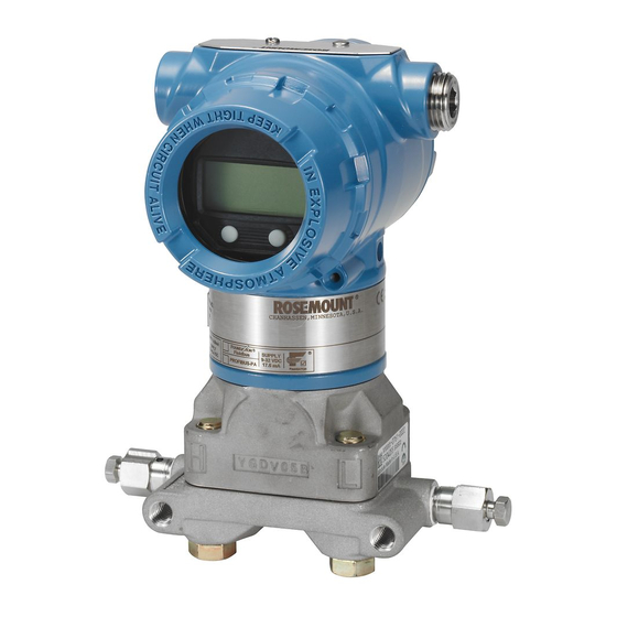
- Page 1 Quick Start Guide 00825-0100-4102, Rev CC May 2017 ™ Rosemount 2051 Pressure Transmitter and Rosemount 2051CF DP Flowmeters ® with WirelessHART Protocol...
-
Page 2: Table Of Contents
May 2017 Quick Start Guide NOTICE This guide provides basic guidelines for Rosemount 2051 Wireless Transmitters. It does not provide instructions for configuration, diagnostics, maintenance, service, troubleshooting or intrinsically safe (I.S.) installations. Refer to the Rosemount 2051 Wireless Reference Manual for more instruction. -
Page 3: Wireless Considerations
Reference Manual. 1.2 Connecting the transmitter with a Field Communicator In order for the Field Communicator to interface with the Rosemount 2051 Wireless, the power module must be connected. This transmitter uses the green power module (order model number 701PGNKF). -
Page 4: Mount The Transmitter
May 2017 Quick Start Guide 2.0 Mount the transmitter 2.1 Mounting in liquid applications 1. Place taps to the side of the line. 2. Mount beside or below the taps. 3. Mount the transmitter so the drain/vent valves are oriented upward. Figure 2. - Page 5 Quick Start Guide May 2017 2.4 Attaching mounting brackets Figure 5. Panel and Pipe Mount Panel mount Pipe mount Coplanar flange Traditional flange In-line...
- Page 6 If the transmitter installation requires assembly of the process flanges, manifolds, or flange adapters, follow these assembly guidelines to ensure a tight seal for optimal performance characteristics of the transmitters. Use only bolts supplied with the transmitter or sold by Emerson as spare parts. Figure 6 illustrates common transmitter assemblies with the bolt length required for proper transmitter assembly.
-
Page 7: Consider Housing Rotation
Quick Start Guide May 2017 Table 1. Torque Values for the Coplanar Flange and Flange Adapter Bolts Bolt material Head markings Initial torque Final torque 300 in-lb 650 in-lb Carbon Steel (CS) Stainless Steel (SST) 150 in-lb 300 in-lb 2.7 In-line gage transmitter orientation The low side pressure port (atmospheric reference) on the in-line gage transmitter is located in the neck of the transmitter, behind the housing. -
Page 8: Connect The Power Module
A zero trim can be performed using either a Field Communicator or configuration buttons. For instructions using AMS Wireless Configurator, see the Rosemount 2051 Wireless Reference Manual. - Page 9 Quick Start Guide May 2017 It is not recommended to zero an absolute transmitter, Rosemount 2051CA or 2051TA models. 5.1 Trimming with a Field Communicator 1. Equalize or vent the transmitter and connect Field Communicator. 2. At the menu, input the HART Fast Key sequence. 3.
-
Page 10: Verify Transmitter Configuration
S R C H N G L I M - O P 6.2 Verify transmitter configuration using Field Communicator For HART Wireless transmitter communication, a Rosemount 2051 Wireless Transmitter Device Descriptor is required. For connecting with a Field Communicator, refer to Figure 1 on page From the Home screen, enter the Fast Key sequence. - Page 11 Quick Start Guide May 2017 Table 2. Device Revision 1, DD Revision 1 Fast Keys Function Fast Keys 2, 1, 1, 1, 1 Date 2, 1, 1, 1, 5 Descriptor 2, 1, 1, 1, 3 Message 2, 1, 1, 1, 4 Long Tag 2, 1, 1, 1, 2 Network ID...
- Page 12 May 2017 Quick Start Guide Figure 11. Gateway Network Settings 6.4 Verifying configuration using AMS Wireless Configurator When the device has joined the network, it will appear in the Wireless Configurator as shown in Figure Figure 12. Wireless Configurator Network Setup...
-
Page 13: Troubleshooting
Network > Settings page on the web interface (see Figure 11 on page 12). The network ID and join key may be changed in the wireless device by using the following Fast Key sequence. See the Rosemount 2051 Wireless Reference Manual for further troubleshooting. -
Page 14: Product Certifications
RF spectrum. Nearly every country requires this type of product certification. Emerson is working with governmental agencies around the world to supply fully compliant products and remove the risk of violating country directives or laws governing wireless device usage. - Page 15 Quick Start Guide May 2017 Special Conditions for Safe Use (X): 1. The Rosemount 2051 Wireless Pressure Transmitter shall only be used with the ™ 701PGNKF Rosemount SmartPower Battery Pack. 2. The in-line pressure sensor may contain more than 10% aluminum and is considered a potential risk of ignition by impact or friction.
- Page 16 May 2017 Quick Start Guide Special Condition for Safe Use (X): 1. See certificate for special conditions. China I3 China Intrinsic Safety Certificate: GYJ12.1295X, GYJ15.1365X [Flowmeters] Standards: GB3836.1-2010, GB3836.4-2010, GB3836.20-2010 Markings: Ex ia IIC Ga T4, –40 ~ 70 °C Special Condition for Safe Use (X): 1.
- Page 17 Quick Start Guide May 2017 Figure 13. Rosemount 2051 Wireless Declaration of Conformity...
- Page 18 May 2017 Quick Start Guide...
- Page 19 Quick Start Guide May 2017...
- Page 20 May 2017 Quick Start Guide Rosemount 2051 China RoHS List of Rosemount 2051 Parts with China RoHS Concentration above MCVs / Hazardous Substances Hexavalent Polybrominated Polybrominated Part Name Lead Mercury Cadmium Chromium biphenyls diphenyl ethers (Pb) (Hg) (Cd) (Cr +6)
- Page 21 Quick Start Guide May 2017...
- Page 22 1 Pandan Crescent Singapore 128461 Standard Terms and Conditions of Sale can be found at +65 6777 8211 www.Emerson.com/en-us/Terms-of-Use The Emerson logo is a trademark and service mark of Emerson +65 6777 0947 Electric Co. Enquiries@AP.EmersonProcess.com SmartPower, Rosemount, and Rosemount logotype are trademarks of Emerson.
Need help?
Do you have a question about the Rosemount 2051 and is the answer not in the manual?
Questions and answers