Emerson Rosemount 2051 Reference Manual
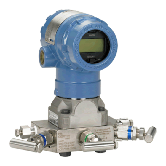
Pressure transmitter
Hide thumbs
Also See for Rosemount 2051:
- Reference manual (228 pages) ,
- Quick start manual (48 pages) ,
- Quick installation manual (25 pages)

Related Manuals for Emerson Rosemount 2051


Summary of Contents for Emerson Rosemount 2051
- Page 1 Reference Manual 00809-0100-4101, Rev BB March 2024 Rosemount ™ 2051 Pressure Transmitter with 4-20 mA HART and 1-5 Vdc Low Power Protocol ®...
- Page 2 Do not attempt to loosen or remove flange bolts while the transmitter is in service. Replacement equipment or spare parts not approved by Emerson for use as spare parts could reduce the pressure retaining capabilities of the transmitter and may render the instrument dangerous.
- Page 3 The products described in this document are NOT designed for nuclear-qualified applications. Using non-nuclear qualified products in applications that require nuclear-qualified hardware or products may cause inaccurate readings. For information on Rosemount nuclear-qualified products, contact your local Emerson Sales Representative.
-
Page 5: Table Of Contents
Reference Manual Contents 00809-0100-4101 March 2024 Contents Chapter 1 Introduction..........................7 1.1 Service support..........................7 1.2 Models covered..........................7 1.3 Transmitter overview........................8 Chapter 2 Installation..........................11 2.1 Overview.............................11 2.2 General considerations......................11 2.3 Mechanical considerations.......................11 2.4 Environmental considerations....................11 ™ 2.5 HART Installation Flowchart....................12 2.6 Electrical considerations......................25 2.7 Hazardous locations certifications..................31 2.8 Rosemount 304, 305, and 306 Manifolds................32 2.9 Liquid level measurement......................35 Chapter 3 ... - Page 6 Reference Manual March 2024 00809-0100-4101 A.1 Performance Specifications..................... 93 A.2 Functional Specifications......................96 A.3 Physical Specifications......................101 A.4 Ordering Information......................105 A.5 Options............................. 117 A.6 Spare Parts..........................119 Appendix B Approval Information......................125 B.1 Overview..........................125 B.2 Approved Manufacturing Locations..................125 B.3 European Directive Information................... 125 B.4 HART Protocol..........................126 B.5 Approval Drawings......................... 130 Appendix C Glossary..........................143 Emerson.com/Rosemount...
-
Page 7: Chapter 1 Introduction
Introduction 1.1 Service support To expedite the return process outside of the United States, contact the nearest Emerson representative. Within the United States, contact Emerson.com/Contact. This center, available 24 hours a day, will assist you with any needed information or materials. -
Page 8: Transmitter Overview
Transmitter overview The Rosemount 2051C Coplanar design is offered for Differential Pressure (DP) and Gage Pressure (GP) measurements where it uses Emerson capacitance sensor technology. Piezoresistive sensor technology is used in the Rosemount 2051T measurements. The major components of the Rosemount 2051C are the sensor module and the electronics housing. - Page 9 Reference Manual Introduction 00809-0100-4101 March 2024 Figure 1-1: Block diagram of operation A. Sensor module B. Electronics board C. 4-20 mA signal to control system D. HART communicator E. Signal processing F. Temperature G. Sensor module memory H. Microcomputer • Sensor linearization •...
- Page 10 Introduction Reference Manual March 2024 00809-0100-4101 Emerson.com/Rosemount...
-
Page 11: Chapter 2 Installation
2 Installation 2.1 Overview The information in this section covers installation considerations for the Rosemount 2051 with HART protocols. A Quick Start Guide for HART protocol is shipped with every ® transmitter to describe basic pipe-fitting and wiring procedures for initial installation. -
Page 12: Hart ™ Installation Flowchart
Installation Reference Manual March 2024 00809-0100-4101 2.5 HART Installation Flowchart ™ Figure 2-1: HART Installation Flowchart Emerson.com/Rosemount... - Page 13 Always ensure a proper seal by installing the electronics housing covers so that metal contacts metal. Use Rosemount O-rings. Mounting brackets Rosemount 2051 Transmitters may be panel-mounted or pipe-mounted through an optional mounting bracket. Refer to Table 2-1 for the complete offering and see...
- Page 14 Figure 2-2: Mounting Bracket Option Code B4 –16 3 bolts for mounting to transmitter 11/4 bolts for panel mounting (not supplied) 5/16 11/2 Figure 2-3: Mounting Bracket Option Codes B1, B7, and BA Emerson.com/Rosemount...
- Page 15 Reference Manual Installation 00809-0100-4101 March 2024 Figure 2-4: Panel Mounting Bracket Option Codes B2 and B8 A. Mounting holes 0.375 diameter (10) Note Dimensions are in inches (millimeters). Figure 2-5: Flat Mounting Bracket Option Codes B3 and BC Note Dimensions are in inches (millimeters). Flange bolts The 2051 is shipped with a Coplanar flange installed with four 1.75-in.
- Page 16 The last digit in the F593 head marking may be any letter between A - M. Bolt installation NOTICE Only use bolts supplied with the 2051 or provided by Emerson as spare parts. When installing the transmitter to one of the optional mounting brackets, torque the bolts to 125 in-lb. (0,9 N-m).
- Page 17 Reference Manual Installation 00809-0100-4101 March 2024 Table 2-3: Traditional flange bolt configurations Differential transmitter Gauge transmitter a. Drain/vent b. Plug Table 2-4: Mounting bolts and bolt configurations for coplanar flange Transmitter with flange bolts Transmitter with flange adapters and flange/adapter bolts Reference Manual...
- Page 18 • Prevent sediment deposits in the impulse piping. • Maintain equal leg of head pressure on both legs of the impulse piping. • Avoid conditions that might allow process fluid to freeze within the process flange. Emerson.com/Rosemount...
- Page 19 Reference Manual Installation 00809-0100-4101 March 2024 Mounting requirements Impulse piping configurations depend on specific measurement conditions. Refer to Installation examples for examples of the following mounting configurations. Liquid flow measurement • Place taps to the side of the line to prevent sediment deposits on the process isolators. •...
- Page 20 Installation Reference Manual March 2024 00809-0100-4101 Figure 2-8: Gas service A. Flow Figure 2-9: Steam service A. Flow Emerson.com/Rosemount...
- Page 21 Reference Manual Installation 00809-0100-4101 March 2024 2.5.4 Process connections WARNING Failure to install proper flange adapter O-rings may cause process leaks, which can result in death or serious injury. The two flange adapters are distinguished by unique O-ring grooves. Only use the O-ring that is designed for its specific flange adapter. NOTICE Coplanar or Traditional process connection Install and tighten all four flange bolts before applying pressure, or process leakage will...
- Page 22 1. Loosen the housing rotation set screw using a 5/64-in. hex wrench. 2. Turn the housing left or right up to 180 degrees from its original position. Over- rotating will damage the transmitter. 3. Re-tighten the housing rotation set screw. Emerson.com/Rosemount...
- Page 23 Reference Manual Installation 00809-0100-4101 March 2024 Figure 2-10: Housing rotation a. Housing rotation set screw (5/64-in) 2.5.6 LCD display Transmitters ordered with the LCD option are shipped with the display installed. Installing the display on an existing 2051 transmitter requires a small instrument screwdriver. Figure 2-11: LCD display A.
- Page 24 2.5.7 Configure security and alarm Security (Write protect) There are three security methods with the Rosemount 2051 transmitter: Procedure 1. Security Jumper: prevents all writes to transmitter configuration. 2. Local Keys (Local Zero and Span) Software Lock Out: prevents changes to transmitter range points via local zero and span adjustment keys.
-
Page 25: Electrical Considerations
Reference Manual Installation 00809-0100-4101 March 2024 Figure 2-12: Electronics board 4-20 mA HART Without LCD meter With LCD display A. Alarm B. Security Figure 2-13: Low Power transmitter electronics boards 1-5 Vdc HART low power Without LCD meter With LCD display ... - Page 26 Do not connect the power signal wiring to the test terminals. Voltage may burn out the reverse-polarity protection diode in the test connection. Note Use shielded twisted pairs to yield best results. To ensure proper communication, use 24 AWG or larger wire, and do not exceed 5000 feet (1500 meters). Emerson.com/Rosemount...
- Page 27 Reference Manual Installation 00809-0100-4101 March 2024 Figure 2-15: 4-20 mA HART wiring A. R ≥ 250Ω B. Power supply Figure 2-16: 1-5 VDC low power wiring A. Voltmeter B. Power supply Perform the following procedure to make wiring connections: Procedure 1. Remove the housing cover on terminal compartment side. CAUTION Do not remove the cover in explosive atmospheres when the circuit is live.
- Page 28 Power supply for 1-5 Vdc HART low power Low power transmitters operate on 9–28 Vdc. The dc power supply should provide power with less than two percent ripple. The V load should be 100 kΩ or greater. Emerson.com/Rosemount...
- Page 29 Reference Manual Installation 00809-0100-4101 March 2024 2.6.3 Transient protection terminal block The transmitter will withstand electrical transients of the energy level usually encountered in static discharges or induced switching transients. However, high-energy transients, such as those induced in wiring from nearby lightning strikes, can damage the transmitter. The transient protection terminal block can be ordered as an installed option (Option Code T1 in the transmitter model number) or as a spare part to retrofit existing 2051 transmitters in the field.
- Page 30 Internal Ground Connection: The Internal Ground Connection screw is inside the FIELD TERMINALS side of the electronics housing. This screw is identified by a ground symbol ). The ground connection screw is standard on all Rosemount 2051 transmitters. Refer to Figure 2-20.
-
Page 31: Hazardous Locations Certifications
Reference Manual Installation 00809-0100-4101 March 2024 Figure 2-20: Internal ground screw A. Internal ground connection screw Figure 2-21: External ground assembly A. External ground assembly Note Grounding the transmitter case via threaded conduit connection may not provide sufficient ground continuity. 2.7 Hazardous locations certifications NOTICE Individual transmitters are clearly marked with a tag indicating the approvals they carry. -
Page 32: Rosemount 304, 305, And 306 Manifolds
When fully tightened, the bolts should extend through the top of the sensor module housing. 3. Leak-check assembly to maximum pressure range of transmitter. 2.8.2 Rosemount 305 Integral Manifold installation procedure To install a 305 Integral Manifold to a 2051 transmitter: Emerson.com/Rosemount... - Page 33 Reference Manual Installation 00809-0100-4101 March 2024 Procedure 1. Inspect the PTFE sensor module O-rings. Note Undamaged O-rings may be reused. If the O-rings are damaged (if they have nicks or cuts, for example), replace with O-rings designed for Rosemount transmitter. Note If replacing the O-rings, take care not to scratch or deface the O-ring grooves or the surface of the isolating diaphragm while you remove the damaged O-rings.
- Page 34 Next, open the center (equalize) valve(s) to equalize the pressure on both sides of the transmitter. The manifold valves are now in the proper configuration for zeroing the transmitter. To return the transmitter to service, close the equalizing valve(s) first. Emerson.com/Rosemount...
-
Page 35: Liquid Level Measurement
Reference Manual Installation 00809-0100-4101 March 2024 (continued) Table 2-7: Three-valve configuration Next, open the isolate valve on the low pressure side of the transmitter. 2.9 Liquid level measurement Differential pressure transmitters used for liquid level applications measure hydrostatic pressure head. Liquid level and specific gravity of a liquid are factors in determining pressure head. - Page 36 The pipe is purposely filled with a convenient reference fluid to eliminate this potential error. This is a wet leg condition. The reference fluid will exert a head pressure on the low side of the transmitter. Zero elevation of the range must then be made. See Figure 2-24. Emerson.com/Rosemount...
- Page 37 Reference Manual Installation 00809-0100-4101 March 2024 Figure 2-24: Wet leg example Let X equal the vertical distance between the minimum and maximum measurable levels (500 in.). Let Y equal the vertical distance between the transmitter datum line and the minimum measurable level (50 in.). Let Z equal the vertical distance between the top of the liquid in the wet leg and the transmitter datum line (600 in.).
- Page 38 Bubble air through the tube at a constant flow rate. The pressure required to maintain flow equals the liquid’s specific gravity multiplied by the vertical height of the liquid above the tube opening. Figure 2-25 shows a bubbler liquid level measurement example. Emerson.com/Rosemount...
- Page 39 Reference Manual Installation 00809-0100-4101 March 2024 Figure 2-25: Bubbler liquid level measurement example A. Air Let X equal the vertical distance between the minimum and maximum measurable levels (100 in.). Let SG equal the specific gravity of the fluid (1.1). Let h equal the maximum head pressure to be measured in inches of water. Let Range equal zero to h.
- Page 40 Installation Reference Manual March 2024 00809-0100-4101 Emerson.com/Rosemount...
-
Page 41: Chapter 3 Configuration
Send key (F2). AMS Device Manger configuration changes are implemented when the Apply button is selected. For more information on the Field Communicator, see Emerson.com/global. AMS Device Manger help can be found in the AMS Device Manager online guides within the AMS system. -
Page 42: Review Configuration Data
B. Power supply 3.3 Review configuration data Note Information and procedures in this section that make use of Field Communicator Fast Key sequences and AMS Device Manager assume the transmitter and communication equipment are connected, powered, and operating correctly. Emerson.com/Rosemount... - Page 43 Reference Manual Configuration 00809-0100-4101 March 2024 The following is a list of factory default configurations. These can be reviewed by using the Field Communicator or AMS Device Manager. Field Communicator Table 3-1: Fast keys 4–20 mA Fast Keys 1, 5 1–5 Vdc Fast Keys 1, 5 Enter the Fast Key sequence to view the configuration data.
-
Page 44: Hart Communicator Menu Trees
Configuration Reference Manual March 2024 00809-0100-4101 3.4 HART Communicator menu trees Rosemount 2051 HART menu tree for 4-20 mA HART output Emerson.com/Rosemount... -
Page 45: Fast Key Sequence
3.5 Fast Key sequence A check (✓) indicates the basic configuration parameters. At minimum, these parameters should be verified as part of the configuration and startup procedure. Table 3-3: Rosemount 2051 Fast Key Sequence Function 4–20 mA HART 1–5 Vdc HART low... -
Page 46: Check Output
Configuration Reference Manual March 2024 00809-0100-4101 (continued) Table 3-3: Rosemount 2051 Fast Key Sequence Function 4–20 mA HART 1–5 Vdc HART low power Descriptor 1, 3, 4, 2 1, 3, 4, 2 Digital To Analog Trim (4–20 mA Output) -
Page 47: Basic Setup
• Analog output 3.6.2 Sensor temperature The Rosemount 2051 contains a temperature sensor near the pressure sensor in the sensor module. When reading this temperature, keep in mind the sensor is not a process temperature reading. Field Communicator Table 3-5: Fast keys 4–20 mA Fast Keys... - Page 48 3.7.2 Set output (transfer function) The Rosemount 2051 has two output settings: Linear and square root. Activate the square root output option to make analog output proportional to flow. As input approaches zero, the Rosemount 2051 automatically switches to linear output in order to ensure a more...
- Page 49 (zero to upper range limit). Note Regardless of the range points, Rosemount 2051 will measure and report all readings within the digital limits of the sensor. For example, if the 4 and 20 mA points are set to 0 and 10 inH...
- Page 50 1. Enter the Lower Range Value (LRV) and the Upper Range Value (URV) in the fields provided. Select Apply. 2. An Apply Parameter Modification screen appears, enter desired information and select OK. 3. After carefully reading the warning provided, select OK. Emerson.com/Rosemount...
- Page 51 Reference Manual Configuration 00809-0100-4101 March 2024 Rerange with a pressure input source and a Field Communicator or AMS Device Manager Reranging using the Field Communicator and applied pressure is a way of reranging the transmitter when specific 4 and 20 mA points (1 and 5 Vdc points) are not calculated. Note The span is maintained when the 4 mA point (1 Vdc point) is set.
- Page 52 Keys or going to configure in AMS Device Manager. Field Communicator Table 3-10: Fast keys 4–20 mA Fast Keys 1, 3, 6 1–5 Vdc Fast Keys 1, 3, 6 AMS Device Manager Right-click on the device and select Configure Properties from the menu. Emerson.com/Rosemount...
-
Page 53: Lcd Display
Reference Manual Configuration 00809-0100-4101 March 2024 Procedure 1. In the Basic Setup tab, enter the damping value in the Damp field, select Apply. 2. An Apply Parameter Modification screen appears, enter desired information and select OK. 3. After carefully reading the warning provided, select OK. 3.8 ... - Page 54 Select 1 Sel dec pt pos. Choose the decimal point representation that will provide the most accurate output for your application. For example, when outputting between 0 and 75 GPM, choose XX.XXX or use the decimal point examples below: • XXXXX Emerson.com/Rosemount...
-
Page 55: Detailed Setup
Reference Manual Configuration 00809-0100-4101 March 2024 • XXXX.X • XXX.XX • XX.XXX • X.XXXX Note Ensure the selection has been sent and the decimal point has changed before proceeding to the next step. 4. SEND. 5. To specify a custom upper range value: a) Select 2 CM Upper Value. - Page 56 Primary variable is burst normally • Temperature is burst normally 3.9.3 Alarm and saturation values for multidrop mode Transmitters set to multidrop mode handle saturation and alarm conditions differently. Alarm conditions: • Primary variable is sent with a status bit set Emerson.com/Rosemount...
-
Page 57: Diagnostics And Service
Reference Manual Configuration 00809-0100-4101 March 2024 • Percent of range follows primary variable • Temperature is sent with a status bit set Saturation: • Primary variable is sent normally • Temperature is sent normally 3.9.4 Alarm level verification If the transmitter electronics board, sensor module, or LCD display is repaired or replaced, verify the transmitter alarm level before returning the transmitter to service. - Page 58 For 4–20 mA HART output, connect a reference meter to the transmitter by ® either connecting the meter to the test terminals on the terminal block, or shunting transmitter power through the meter at some point in the loop. Emerson.com/Rosemount...
-
Page 59: Advanced Functions
Saving, recalling, and cloning configuration data Use the cloning feature of the Field Communicator or the AMS Device Manager “User Configuration” feature to configure several Rosemount 2051 transmitters similarly. Cloning involves configuring a transmitter, saving the configuration data, then sending a copy of the data to a separate transmitter. - Page 60 5. Transfer values from the current configuration to the user configuration as appropriate or enter values by typing the values into the available fields. 6. Click Apply to apply the values, or click OK to apply the values and close the window. Emerson.com/Rosemount...
- Page 61 Reference Manual Configuration 00809-0100-4101 March 2024 AMS device manager applying a user configuration Any amount of user configurations can be created for the application. They can also be saved, and applied to connected devices or to devices in the Device List or Plant Database. Note When using AMS Device Manager Revision 6.0 or later, the device to which the user configuration is applied, must be the same model type as the one created in the user...
-
Page 62: Multidrop Communication
Note A transmitter in multidrop mode has the analog output fixed at 4 mA. If an LCD display is installed to a transmitter in multidrop mode, it will alternate the display between “current fixed” and the specified LCD display output(s). Emerson.com/Rosemount... - Page 63 Reference Manual Configuration 00809-0100-4101 March 2024 Figure 3-6: Typical multidrop network A. HART Modem B. Power Supply The 2051 is set to address zero (0) at the factory, which allows operation in the standard point-to-point manner with a 4–20 mA output signal. To activate multidrop communication, the transmitter address must be changed to a number from 1 to 15.
- Page 64 HART communicator Table 3-21: Fast keys 4-20 mA Fast Keys Left arrow, 4, 1 1-5 Vdc Fast Keys Left arrow, 4, 1 AMS device manager Procedure 1. Click on the HART modem icon. ® 2. Select Scan All Devices. Emerson.com/Rosemount...
-
Page 65: Operation And Maintenance
Operation and Maintenance 4.1 Overview This section contains information on calibrating and diagnostics messages on the Rosemount 2051 Pressure Transmitters. HART Communicator and AMS instructions are given to perform configuration functions. ® For convenience, HART Communicator fast key sequences are labeled “Fast Keys” for each software function below the appropriate headings. - Page 66 2. Set the output units. effects or static pressure effects. 3. Set the output type. c. Optional: Perform an analog 4. Set the damping value. output trim. Accurate multimeter required. b. Optional: Perform a sensor trim. (accurate pressure source required.) Emerson.com/Rosemount...
- Page 67 Reference Manual Operation and Maintenance 00809-0100-4101 March 2024 (continued) Table 4-1: Recommended Calibration Tasks Transmitter Bench calibration tasks Field calibration tasks 2051TA a. Set output configuration a. Reconfigure parameters if parameters: necessary. 2051TG, Range 5 1. Set the range points. b. Perform low trim value section of the sensor trim procedure 2.
- Page 68 O (374 mbar) Ambient temperature change: ± 50 °F (28 °C) Line pressure: 500 psig (34,5 bar) 3. Calculate total probable error (TPE). TPE = = 0.185 % of span Zero static pressure effect removed by zero trimming at line pressure. Emerson.com/Rosemount...
-
Page 69: Analog Output Trim
Reference Manual Operation and Maintenance 00809-0100-4101 March 2024 Where: Reference Accuracy = ± 0.065% of span Ambient Temperature Effect = Span Static Pressure Effect = 0.1% reading per 1000 psi (69 bar) = ±0.05% of span at maxium span 4. Calculate the stability per month. 5. - Page 70 4.0 mA. 5. Record the actual value from the reference meter, and enter it at the Enter meter value prompt. The HART Communicator prompts you to verify whether or not the output value equals the value on the reference meter. Emerson.com/Rosemount...
- Page 71 Reference Manual Operation and Maintenance 00809-0100-4101 March 2024 6. Select 1: Yes, if the reference meter value equals the transmitter output value, or 2: No if it does not. a) If 1 is selected: Yes, proceed to Step 7. b) If 2 is selected: No, repeat Step 5. 7.
- Page 72 2. Select Analog output trim under Trim to recall and click Next. 3. Click Next to acknowledge restoration of trim values is complete. 4. Select Next to acknowledge the loop can be returned to automatic control. 5. Select Finish to acknowledge the method is complete. Emerson.com/Rosemount...
-
Page 73: Sensor Trim
Reference Manual Operation and Maintenance 00809-0100-4101 March 2024 4.4 Sensor trim 4.4.1 Sensor trim overview Trim the sensor using either sensor or zero trim functions. Trim functions vary in complexity and are application-dependent. Both trim functions alter the transmitter’s interpretation of the input signal. Zero trim is a single-point offset adjustment. - Page 74 Examples: Calibration: 0 to 100 inH O - lower trim = 0, upper trim = 100 Calibration: -100 to 0 inH O - lower trim = 0, upper trim = -100 Emerson.com/Rosemount...
- Page 75 Reference Manual Operation and Maintenance 00809-0100-4101 March 2024 Calibration: -100 to 100 inH O - lower trim = -100 or 100, upper trim = -100 or 100 Note Select pressure input values so that lower and upper values are equal to or outside the 4 and 20 mA (1 and 5 Vdc) points.
- Page 76 3) do not require this procedure because optimization occurs in the sensor. Applying high static pressure to Rosemount 2051 range 4 and range 5 pressure transmitters causes a systematic shift in the output. This shift is linear with static pressure;...
- Page 77 Reference Manual Operation and Maintenance 00809-0100-4101 March 2024 LT = 500 inH O – (–1%/100 × 1200 psi/1000 × 500 inH LT = 506 inH High trim value HT = (URV – (S/100 × P/1000 × URV) Where: HT = Corrected high trim value ...
- Page 78 Operation and Maintenance Reference Manual March 2024 00809-0100-4101 Emerson.com/Rosemount...
-
Page 79: Chapter 5 Troubleshooting
Reference Manual Troubleshooting 00809-0100-4101 March 2024 5 Troubleshooting 5.1 Overview The following sections provide summarized maintenance and troubleshooting suggestions for the most common operating problems. 5.2 Troubleshooting for 4-20 mA output 5.2.1 Transmitter milliamp reading is zero Recommended actions 1. Verify terminal voltage is 10.5 to 42.4 Vdc at signal terminals. 2. -
Page 80: Troubleshooting For 1-5 Vdc Output
Recommended actions 1. Verify terminal voltage is 5.8 to 28.0 Vdc at signal terminals. 2. Check power wires for reversed polarity. 3. Check that power wires are connected to signal terminals. 4. Check for open diode across test terminal. Emerson.com/Rosemount... - Page 81 Reference Manual Troubleshooting 00809-0100-4101 March 2024 5.3.2 Transmitter not communicating with communication device Recommended actions 1. Verify terminal voltage is 5.8 to 28.0 Vdc. 2. Check loop resistance. (Power supply voltage - transmitter voltage)/loop current should be 250 Ω minimum. 3. Check that power wires are connected to signal terminals and not test terminals.
-
Page 82: Diagnostic Messages
Recommended actions 1. Ensure the sensor cable connection to the electronics is tight. 2. Replace the transmitter. Electronics Board Failure A failure has been detected in the electronics circuit board. LCD display FAIL BOARD FAIL BOARD Local Operator Interface (LOI) Emerson.com/Rosemount... - Page 83 Reference Manual Troubleshooting 00809-0100-4101 March 2024 Recommended action Replace the pressure transmitter. Critical Sensor Data Error LCD display MEMRY ERROR screen MEMORY ERROR Local Operator Interface (LOI) screen A user-written parameter does not match the expected value. Recommended actions 1. Confirm and correct all parameters listed in Device Information. 2.
- Page 84 1. Check the process and ambient conditions are within -85 to 194 °F (-65 to 90 °C). 2. Replace the pressure transmitter. Electronics Temperature Beyond Limits LCD display TEMP LIMITS screen TEMP OUT LIMITS Local operator interface (LOI) screen Emerson.com/Rosemount...
- Page 85 Reference Manual Troubleshooting 00809-0100-4101 March 2024 The electronics temperature has exceeded its safe operating range. Recommended actions 1. Confirm electronics temperature is within limits of -85 to +194 °F (-65 to +90 °C). 2. Replace the pressure transmitter. Electronics Board Parameter Error LCD display MEMRY WARN (also in advisory) screen...
- Page 86 2. Clear this alert by selecting Clear Configuration Changed Status. 3. Connect a HART master, such as AMS Device Manager or similar, which will automatically clear the alert. Analog Output Fixed ANLOG FIXED LCD display screen ANALOG FIXED Local Operator Interface (LOI) screen Emerson.com/Rosemount...
-
Page 87: Disassembly Procedures
Reference Manual Troubleshooting 00809-0100-4101 March 2024 The analog output is fixed and does not represent the process measurement. This may be caused by other conditions in the device or because the device has been set to Loop Test or Multidrop mode. Recommended actions 1. - Page 88 1. Remove the housing cover opposite the field terminal side. 2. If you are disassembling a transmitter with an LCD display, loosen the two captive screws that are visible on the right and left side of the meter display. Emerson.com/Rosemount...
-
Page 89: Reassembly Procedures
Reference Manual Troubleshooting 00809-0100-4101 March 2024 NOTICE The two screws anchor the LCD display to the electronics board and the electronics board to the housing. The electronics board is electrostatically sensitive. Observe handling precautions for static-sensitive components. Use caution when removing the LCD, as there is an electronic pin connector that interfaces between the LCD and electronics board. - Page 90 Do not force. The electronics board should slide gently on the connections. 4. Tighten the captive mounting screws. 5. Replace the electronics housing cover. WARNING The transmitter covers must be engaged metal-to-metal to ensure a proper seal and to meet explosion-proof requirements. Emerson.com/Rosemount...
- Page 91 Reference Manual Troubleshooting 00809-0100-4101 March 2024 5.6.3 Install the terminal block Procedure 1. Gently slide the terminal block into place. Note Ensure the two posts from the electronics housing properly engage the receptacles on the terminal block. 2. Tighten the captive screws. 3.
- Page 92 2. Tighten the drain/vent valve to 250 in.-lb. (28.25 N-m). 3. Ensure the opening is placed on the valve so that process fluid will drain toward the ground and away from human contact when the valve is opened. Emerson.com/Rosemount...
-
Page 93: Appendix A Reference Data
Reference Manual Reference Data 00809-0100-4101 March 2024 A Reference Data A.1 Performance Specifications For zero based spans, reference conditions, silicone oil fill, SST materials, Coplanar flange (2051C) or 1/2 in. - 14 NPT (2051T) process connections, digital trim values range points. Applies to 4-20 mA HART output only unless otherwise noted. - Page 94 ±0.1% of URL/1000 psi (68,9 bar) for line pressures from 0 to 2000 psi (0 to 13,7 MPa) Range 1 ±0.5% of URL/1000 psi (68,9 bar) Span Error Ranges 2-3 ±0.1% of reading/1000 psi (68,9 bar) Range 1 ±0.4% of reading/1000 psi (68,9 bar) Can be calibrated out at line pressure. Emerson.com/Rosemount...
- Page 95 Reference Manual Reference Data 00809-0100-4101 March 2024 Ambient Temperature Effect per 50°F (28°C) Models Ambient Temperature Effect 2051C Ranges 2-5 ±(0.025% URL + 0.125% span) from 1:1 to 5:1 ±(0.05% URL + 0.25% span) from 5:1 to 100:1 Range 1 ±(0.2% URL + 0.5% span) from 1:1 to 50:1 2051T Range 2-4...
-
Page 96: Functional Specifications
5 2000 psi (137,9 bar) 10000 psi (689,4 bar) 0 psia (0 bar) –14.7 psig (–1,01 bar) Assumes atmospheric pressure of 14.7 psig. A.2.1 Service Liquid, gas, and vapor applications A.2.2 Protocols 4–20 mA HART (Output Code A) Output Emerson.com/Rosemount... - Page 97 Reference Manual Reference Data 00809-0100-4101 March 2024 Two-wire 4–20 mA, user-selectable for linear or square root output. Digital process variable superimposed on 4–20 mA signal, available to any host that conforms to the HART ® protocol. Power Supply External power supply required. Standard transmitter operates on 10.5 to 42.4 Vdc with no load.
- Page 98 HART protocol. Power Supply External power supply required. Standard transmitter operates on 9 to 28 Vdc with no load. Power Consumption 3.0 mA, 27–84 mW Output Load 100 kΩ or greater Turn-On Time Emerson.com/Rosemount...
- Page 99 Reference Manual Reference Data 00809-0100-4101 March 2024 Performance within specifications less than 2.0 sections after power is applied to the transmitter. A.2.3 Overpressure Limits Transmitters withstand the following limits without damage: 2051C • Ranges 2–5: 3626 psig (250 bar) 4500 psig (310,3 bar) for option code P9 •...
- Page 100 Glycerin and Water 0 to 200 °F (–18 to 93 °C) Neobee M-20 0 to 400 °F (–18 to 205 °C) ® LCD display may not be readable and LCD updates will be slower at temperatures below -4 °F (-20 °C). Emerson.com/Rosemount...
-
Page 101: Physical Specifications
Reference Manual Reference Data 00809-0100-4101 March 2024 Table A-3: 2051 Process Temperature Limits (continued) Propylene Glycol and 0 to 200 °F (–18 to 93 °C) Water Process temperatures above 185 °F (85 °C) require derating the ambient limits by a 1.5:1 ratio. 220 °F (104 °C) limit in vacuum service;... - Page 102 • 316L SST or Alloy C-276 Process Isolating Diaphragms • 316L SST or Alloy C-276 A.3.5 2051L Process Wetted Parts Flanged Process Connection (Transmitter High Side) Process Diaphragms, Including Process Gasket Surface • 316L SST or Alloy C-276 Extension Emerson.com/Rosemount...
- Page 103 Reference Manual Reference Data 00809-0100-4101 March 2024 • CF-3M (Cast version of 316L SST, material per ASTM-A743), or Cast C-276. Fits schedule 40 and 80 pipe. Mounting Flange • Zinc-cobalt plated CS or SST Reference Process Connection (Transmitter Low Side) Isolating Diaphragms •...
- Page 104 (5,8) Level Flange—3 in., 300 15.9 (7,2) Level Flange—2 in., 150 8.0 (3,6) Level Flange—2 in., 300 8.4 (3,8) DIN Level Flange, SST, DN 50, PN 40 7.8 (3,5) DIN Level Flange, SST, DN 80, PN 40 12.7 (5,8) Emerson.com/Rosemount...
-
Page 105: Ordering Information
Reference Manual Reference Data 00809-0100-4101 March 2024 A.4 Ordering Information Model Transmitter Type (Select One) 2051C Pressure Transmitter • • Model Measurement Type Differential • — Gage — • Code Pressure Ranges (Range/Min. Span) 2051CD 2051CG –25 to 25 inH O/0.5 –25 to 25 inH O/0.5 inH... - Page 106 Traditional Flange Bracket for 2-in. Pipe Mounting, CS Bolts • • Traditional Flange Bracket for Panel Mounting, CS Bolts • • Traditional Flange Flat Bracket for 2-in. Pipe Mounting, CS Bolts • • Coplanar Flange Bracket for 2-in. Pipe or Panel Mounting, all SST • • Emerson.com/Rosemount...
- Page 107 Reference Manual Reference Data 00809-0100-4101 March 2024 B1 Bracket with Series 300 SST Bolts • • B2 Bracket with Series 300 SST Bolts • • B3 Bracket with Series 300 SST Bolts • • SST B1 Bracket with Series 300 SST Bolts •...
- Page 108 Cleaning for <1 PPM Chlorine/Fluorine • • Special Certifications Calibration Certificate • • Material Traceability Certification per EN 10204 3.1.B • • (17) Prior-use certificate of FMEDA data • • (20) Surface finish certification for sanitary remote seals • • Emerson.com/Rosemount...
- Page 109 Reference Manual Reference Data 00809-0100-4101 March 2024 Calibration certification and tamper evident seal • • (20) Remote Seal System Performance Calculation Report • • Typical Model Number: 2051C D 2 A 2 2 A 1 A B4 M5 Materials of Construction comply with recommendations per NACE MR0175/ISO 15156 for sour oil field production environments.
- Page 110 TIIS Flameproof (consult factory for availability) FM Explosion-proof, Dust Ignition-proof CSA Explosion-proof, Dust Ignition-proof, Division 2 IECEx Flameproof Korea (KOSHA) Flameproof Approval (consult factory for availability) India (CCOE) Flameproof Approval (consult factory for availability) GOST Explosion-proof (consult factory for availability) Emerson.com/Rosemount...
- Page 111 Reference Manual Reference Data 00809-0100-4101 March 2024 ATEX Intrinsic Safety INMETRO Intrinsic Safety (consult factory for availability) China Intrinsic Safety (consult factory for availability) TIIS Intrinsic Safety (consult factory for availability) FM Intrinsically Safe, Division 2 CSA Intrinsically Safe IECEx Intrinsic Safety ATEX FISCO Intrinsic Safety INMETRO FISCO Intrinsic Safety (consult factory for availability) TIIS FISCO Intrinsic Safety (consult factory for availability)
- Page 112 O (–0,6 to 0,6 bar/6,2 mbar) –1000 to 1000 inH O/10 inH O (–2,5 to 2,5 bar/25 mbar) –300 to 300 psi/3 psi (–20,7 to 20,7 bar/0,2 bar) Code Output 4–20 mA with Digital Signal Based on HART Protocol Emerson.com/Rosemount...
- Page 113 Reference Manual Reference Data 00809-0100-4101 March 2024 Low-Power, 1–5 V dc with Digital Signal Based on HART Protocol Foundation fieldbus Protocol Code Diaphragm Size Material Extension Length 2 in./DN 50 316L SST Flush Mount Only 2 in./DN 50 Alloy C-276 Flush Mount Only 3 in./DN 80 316L SST...
- Page 114 SST (consult factory for availability) G½ Code Options Diaphragm Seal Assembly Assemble to one Rosemount 1199 diaphragm seal Product Certifications ATEX Flameproof INMETRO Flameproof (consult factory for availability) China Flameproof (consult factory for availability) TIIS Flameproof (consult factory for availability) Emerson.com/Rosemount...
- Page 115 Reference Manual Reference Data 00809-0100-4101 March 2024 FM Explosion-proof, Dust Ignition-proof CSA Explosion-proof, Dust Ignition-proof, Division 2 IECEx Flameproof Korea (KOSHA) Flameproof Approval (consult factory for availability) India (CCOE) Flameproof Approval (consult factory for availability) GOST Explosion-proof (consult factory for availability) ATEX Intrinsic Safety INMETRO Intrinsic Safety (consult factory for availability) China Intrinsic Safety (consult factory for availability)
- Page 116 T1 option. Only available with HART 4-20mA output (output code A). NAMUR-Compliant operation is pre-set at the factory and cannot be changed to standard operation in the field. Not available with Option Codes A0, B0, and G0. Emerson.com/Rosemount...
-
Page 117: Options
Reference Manual Reference Data 00809-0100-4101 March 2024 A.5 Options Standard Configuration Unless otherwise specified, transmitter is shipped as follows: Engineering Units O (Ranges 1-3), psi (Ranges 4-5) 2051C: Engineering Units psi (all ranges) 2051T: Engineering Units 2051L: 4 mA (1 V dc) 0 (engineering units above) 20 mA (5 V dc) Upper range limit... - Page 118 Rosemount 2051C Traditional Flange Bracket Options B1 Bracket for 2-in. Pipe Mounting • For use with the traditional flange option • Bracket for mounting on 2-in. pipe • Carbon steel construction with carbon steel bolts • Coated with polyurethane paint Emerson.com/Rosemount...
-
Page 119: Spare Parts
Reference Manual Reference Data 00809-0100-4101 March 2024 B2 Bracket for Panel Mounting • For use with the traditional flange option • Bracket for mounting transmitter on wall or panel • Carbon steel construction with carbon steel bolts • Coated with polyurethane paint B3 Flat Bracket for 2-in. - Page 120 Kit includes zero and span hardware adjustments only. O-Ring Packages (package of 12) Part Number Electronic housing, cover (standard and meter) 03031-0232-0001 Electronics housing, module 03031-0233-0001 Process flange, glass-filled PTFE 03031-0234-0001 Process flange, graphite-filled PTFE 03031-0234-0002 Flange adapter, glass-filled PTFE 03031-0242-0001 Flange adapter, graphite-filled PTFE 03031-0242-0002 Emerson.com/Rosemount...
- Page 121 Reference Manual Reference Data 00809-0100-4101 March 2024 Flanges Part Number Differential Coplanar Flange Nickel-plated carbon steel 03031-0388-0025 316 SST 03031-0388-0022 Cast C-276 03031-0388-0023 Gage Coplanar Flange Nickel-plated carbon steel 03031-0388-1025 316 SST 03031-0388-1022 Cast C-276 03031-0388-1023 Coplanar Flange Alignment Screw (package of 12) 03031-0309-0001 Traditional Flange ...
- Page 122 ASTM A 193, Class 2, Grade B8M 03031-0311-0020 TRADITIONAL FLANGE Differential Flange and Adapter Bolt Kit {44 mm (1.75 in.)} (Set of 8) Carbon steel 03031-0307-0001 316 SST 03031-0307-0002 ASTM A 193, Grade B7M 03031-0307-0003 ASTM A 193, Class 2, Grade B8M 03031-0307-0005 Emerson.com/Rosemount...
- Page 123 Reference Manual Reference Data 00809-0100-4101 March 2024 Bolt Kits Part Number Gage Flange and Adapter Bolt Kit (Set of 6) Carbon steel 03031-0307-1001 316 SST 03031-0307-1002 ASTM A 193, Grade B7M 03031-0307-1003 ASTM A 193, Class 2, Grade B8M 03031-0307-1005 Manifold/Traditional Flange Bolts Carbon steel Use bolts supplied with manifold...
- Page 124 Reference Data Reference Manual March 2024 00809-0100-4101 Emerson.com/Rosemount...
-
Page 125: Appendix B Approval Information
B.3 European Directive Information The EC declaration of conformity for all applicable European directives for this product can be found on the Rosemount website at Emerson.com/Rosemount. A hard copy may be obtained by contacting an Emerson representative. ATEX Directive (94/9/EC) All 2051 transmitters comply with the ATEX Directive. -
Page 126: Hart Protocol
= 42.4 Vdc max IP66 IP68 Special Conditions for Safe Use(X) When the optional transient protection terminal block is installed, the apparatus is not capable of withstanding a 500V r.m.s. test to case. This must be taken into account on any Emerson.com/Rosemount... - Page 127 3. The 2051 does not comply with the requirements of IEC 60079-1 Clause 5 for flameproof joints. Contact Emerson for information on the dimensions of flameproof joints. ATEX Dust Certification No. Baseefa08ATEX0182X II 1 D Dust Rating: T80 °C (–20 ≤ T ...
- Page 128 3. The 2051 does not comply with the requirements of IEC 60079-1 Clause 5 for flameproof joints. Contact Emerson for information on the dimensions of flameproof joints. IECEx Type n Certification No. IECExBAS08.0046X II 3 G Ex nAnL IIC T4 (–40 ≤ T ≤ ...
- Page 129 Reference Manual Approval Information 00809-0100-4101 March 2024 Combinations of Certifications Stainless steel certification tag is provided when optional approval is specified. Once a device labeled with multiple approval types is installed, it should not be reinstalled using any other approval types. Permanently mark the approval label to distinguish it from unused approval types.
-
Page 130: Approval Drawings
Approval Information Reference Manual March 2024 00809-0100-4101 B.5 Approval Drawings Factory Mutual (FM) Emerson.com/Rosemount... - Page 131 Reference Manual Approval Information 00809-0100-4101 March 2024 Reference Manual...
- Page 132 Approval Information Reference Manual March 2024 00809-0100-4101 Emerson.com/Rosemount...
- Page 133 Reference Manual Approval Information 00809-0100-4101 March 2024 Reference Manual...
- Page 134 Approval Information Reference Manual March 2024 00809-0100-4101 Emerson.com/Rosemount...
- Page 135 Reference Manual Approval Information 00809-0100-4101 March 2024 Reference Manual...
- Page 136 Approval Information Reference Manual March 2024 00809-0100-4101 Emerson.com/Rosemount...
- Page 137 Reference Manual Approval Information 00809-0100-4101 March 2024 Canadian Standards Association (CSA) Reference Manual...
- Page 138 Approval Information Reference Manual March 2024 00809-0100-4101 Emerson.com/Rosemount...
- Page 139 Reference Manual Approval Information 00809-0100-4101 March 2024 Reference Manual...
- Page 140 Approval Information Reference Manual March 2024 00809-0100-4101 Emerson.com/Rosemount...
- Page 141 Reference Manual Approval Information 00809-0100-4101 March 2024 Reference Manual...
- Page 142 Approval Information Reference Manual March 2024 00809-0100-4101 Emerson.com/Rosemount...
-
Page 143: Appendix C Glossary
Reference Manual Glossary 00809-0100-4101 March 2024 C Glossary Some of the terms used in this manual relate specifically to the operation of Rosemount transmitters, handheld HART Communicators, and other Rosemount products. The ® following list provides brief definitions. See the sections listed for additional information. Analog Output Trim Digital trim operation that allows adjustment of the output electronics to conform to the plant... - Page 144 Highest value of the measured variable that the analog output of the transmitter is currently configured to measure. Zero Trim A zero-based, one-point adjustment used in differential pressure applications to compensate for mounting position effects or zero shifts caused by static pressure. Emerson.com/Rosemount...
- Page 145 Reference Manual 00809-0100-4101 March 2024 Reference Manual...
- Page 146 Emerson Terms and Conditions of Sale are available upon request. The Emerson logo is a trademark and service mark of Emerson Electric Co. Rosemount is a mark of one of the Emerson family of companies. All other marks are the property of their respective owners.
Need help?
Do you have a question about the Rosemount 2051 and is the answer not in the manual?
Questions and answers