Emerson Rosemount 2051 Series Quick Start Manual
Flow meter
Hide thumbs
Also See for Rosemount 2051 Series:
- Reference manual (250 pages) ,
- Quick start manual (52 pages) ,
- Quick start manual (44 pages)

Related Manuals for Emerson Rosemount 2051 Series


Summary of Contents for Emerson Rosemount 2051 Series
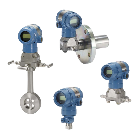
- Page 1 Quick Start Guide 00825-0400-4101, Rev DB October 2023 Rosemount 2051 Pressure ™ Transmitter and Rosemount 2051CF Series Flow Meter with PROFIBUS PA Protocol ®...
- Page 2 In an explosionproof/flameproof installation, do not remove the transmitter covers when power is applied to the transmitter. WARNING Replacement equipment or spare parts not approved by Emerson for use as spare parts could reduce the pressure retaining capabilities of the transmitter and may render the instrument dangerous.
-
Page 3: Table Of Contents
October 2023 Quick Start Guide NOTICE Improper assembly of manifolds to traditional flange can damage sensor module. For safe assembly of manifold to traditional flange, bolts must break back plane of flange web (bolt hole) but must not contact sensor module housing. WARNING Physical access Unauthorized personnel may potentially cause significant damage to and/or... - Page 4 Quick Start Guide October 2023 Emerson.com...
-
Page 5: Mounting The Transmitter
October 2023 Quick Start Guide 1 Mounting the transmitter 1.1 Mount the transmitter in liquid applications Procedure 1. Place taps to the side of the line. 2. Mount the transmitter beside or below the taps. Mount the transmitter so the drain/vent valves are oriented upward. - Page 6 Quick Start Guide October 2023 1.3 Mount the transmitter in steam applications Procedure 1. Place taps to the side of the line. 2. Mount the transmitter beside or below the taps. 3. Fill impulse lines with water. Emerson.com...
- Page 7 October 2023 Quick Start Guide 1.4 Panel and pipe mounting Figure 1-1: Panel and pipe mounting Panel mount Pipe mount Coplanar flange Traditional flange Rosemount 2051 5/16 × 1½ panel bolts are customer supplied. 1.5 Install bolts If the transmitter installation requires assembly of the process flanges, manifolds, or flange adapters, follow the assembly Quick Start Guide...
- Page 8 Quick Start Guide October 2023 guidelines to ensure a tight seal for optimal performance characteristics of the transmitter. Use only bolts supplied with the transmitter or sold by Emerson as spare parts. Figure 1-2 illustrates common transmitter assemblies with the bolt length required for proper transmitter assembly.
- Page 9 October 2023 Quick Start Guide Table 1-1 for final torque value. 4. Verify the flange bolts are protruding through the sensor module bolt holes before applying pressure. Table 1-1: Torque values for the flange and flange adapter bolts Bolt Head markings Initial Final torque material...
- Page 10 The vent path is 360° around the transmitter between the housing and sensor. (See Figure 1-4.) Keep the vent path free of any obstruction, including but not limited to paint, dust, and lubrication by mounting the transmitter so fluids can drain away. Emerson.com...
- Page 11 October 2023 Quick Start Guide Figure 1-4: In-line gauge low side pressure port A. Pressure port location Quick Start Guide...
-
Page 12: Rotate Housing
3. If the desired location cannot be achieved due to thread limitation, rotate the housing counterclockwise to the desired location (up to 360° from thread limit). 4. Retighten the housing rotation set screw to no more than 7 in.-lbs. when desired location is reached. Emerson.com... -
Page 13: Setting Jumpers And Switches
October 2023 Quick Start Guide 3 Setting jumpers and switches 3.1 Security jumper After the transmitter is configured, you may want to protect the configuration data from unwarranted changes. Each transmitter is equipped with a security jumper that can be positioned to prevent the accidental or deliberate change of configuration data. -
Page 14: Connect Wiring And Power Up
When using a direct wiring method, wrap wire clockwise to ensure it is in place when tightening the terminal block screw. NOTICE Emerson does not recommend using a pin or a ferrule wire terminal, as the connection may be more susceptible to loosening over time or under vibration. - Page 15 October 2023 Quick Start Guide Example Figure 4-1: Terminals A. Power terminals B. Ground terminal Quick Start Guide...
- Page 16 Ground signal wiring WARNING Do not run signal wiring in conduit or open trays with power wiring or near heavy electrical equipment. Grounding terminations are provided on the outside of the electronics housing and inside the terminal compartment. These Emerson.com...
- Page 17 B. Insulate shield C. Connect shield back to the power supply ground 3. Replace the housing cover. Emerson recommends tightening the cover until there is no gap between the cover and the housing. 4. Plug and seal unused conduit connections.
- Page 18 Transmitters are electrically isolated to 500 Vac rms. Signal wiring cannot be grounded. 4.1.4 Shield wire ground Shield wire usually requires a single grounding point to avoid creating a ground loop. The ground point is typically at the power supply. Emerson.com...
-
Page 19: Basic Configuration
October 2023 Quick Start Guide 5 Basic configuration 5.1 Configuration tasks The transmitter can be configured via either the local operator interface (LOI) – option code M4, or via a Class 2 master (DD or ™ based). The two basic configuration tasks for the PROFIBUS PA Pressure transmitter are: Procedure 1. - Page 20 LOWER SENSOR 4. DAMPING FLOW UPPER SENSOR LEVEL 5. DISPLAY RESET FACTORY TEMPERATURE 6. IDENTIFICATION # 7. EXIT 5.3 Class 2 Master The Rosemount 2051 PROFIBUS DD and DTM files are available at Emerson.com/Rosemount or by contacting your local salesperson. Emerson.com...
- Page 21 Generic (pa139700.gsd). These files can be found on Emerson.com/ Rosemount or Profibus.com. 5.4.2 Configuration host (Class 2) The appropriate DD or DTM file must be installed in the configuration host. These files can be found at Emerson.com/Rosemount. Quick Start Guide...
-
Page 22: Trim The Transmitter
1. Place the transducer block into Out of Service (OOS) mode. 2. Apply zero pressure to device and allow to stabilize. 3. Go to Basic Setup > Calibration and set the lower calibration point to 0.0. 4. Place the transducer block to AUTO mode. Emerson.com... -
Page 23: Rosemount 2051 Product Certifications
European directive information A copy of the EU Declaration of Conformity can be found at the end of the Quick Start Guide. The most recent revision of the EU Declaration of Conformity can be found at Emerson.com/Rosemount. 7.2 Ordinary location certification... - Page 24 T1) will not pass the 500 VRMS dielectric strength test; this must be considered during installation. 3. Equipment evaluated for atmospheric pressure range between 80 kPa (0.8 bar) to 110 kPa (1.1 bar). 4. Maximum process temperature limits shall be in accordance with 03031-1053. Emerson.com...
- Page 25 October 2023 Quick Start Guide IE USA FISCO 2041384 Certificate FM 3600: 2022, FM 3610: 2021, FM 3611: 2021, Standards ANSI/UL 61010-1-2019 Third Edition, ANSI/UL 60079-0: 2017, ANSI/UL 60079-11: 2013, ANSI/UL 12.27.01: 2022 (Fourth Edition), ANSI/UL 50E (First Edition) IS: CL I GP ABCD T4 Markings CL I ZN 0 AEx ia IIC T4 Ga -50 °C ≤...
- Page 26 3. Equipment evaluated for atmospheric pressure range between 80 kPa (0.8 bar) to 110 kPa (1.1 bar). IF Canada FISCO 2041384 Certificate C22.2 No. 61010-1-12, C22.2 No. 25-17, C22.2 No. Standards 94.2-20 Third Edition, CSA Std C22.2 No. 213-17 + Emerson.com...
- Page 27 October 2023 Quick Start Guide UPD 1 (2018) + UPD 2 (2019) + UPD 3 (2021), CAN/ CSA-60079-0:19, CAN/CSA-60079-11:14, ANSI/UL 12.27.01:2022 (Fourth Edition), ANSI/UL 50E (First Edition) IS: CL I GP ABCD T4; Markings: Ex ia IIC T4 Ga -50 °C ≤ Ta ≤ +60 °C FISCO Install per 02051-1008 Single seal - temp limits per 03031-1053...
- Page 28 Ex certified plugs, glands, or adapters in cable/conduit entries. I1 ATEX Intrinsic Safety Baseefa08ATEX0129X Certificate EN IEC 60079-0: 2018, EN60079-11: 2012 Standards Markings II 1 G Ex ia IIC T4 Ga (–60 °C ≤ Ta ≤ +70 °C) Emerson.com...
- Page 29 October 2023 Quick Start Guide Table 7-2: Input parameters HART Fieldbus/PROFIBUS ® ® Voltage U 30 V 30 V Current I 200 mA 300 mA Power P 1.3 W Capacitance C 0.012 μF 0 μF Inductance L 0 mH 0 mH Special Conditions for Safe Use (X): 1.
- Page 30 Avoid installations that could cause electrostatic build-up on painted surfaces and only clean the painted surfaces with a damp cloth. If paint is ordered through a special option code, contact the manufacturer for more information. 7.6 International E7 IECEx Flameproof IECExKEM08.0024X Certificate Emerson.com...
- Page 31 October 2023 Quick Start Guide IEC 60079-0: 2017, IEC 60079-1: 2014-06, IEC Standards 60079-26: 2014-10 Ex db IIC T6…T4 Ga/Gb T6 (–60 °C ≤ Ta ≤ +70 °C), Markings T4/T5 (–60 °C ≤ Ta ≤ +80 °C) Table 7-4: Process connection temperature Temperature class Process connection Ambient temperature...
- Page 32 IG IECEx FISCO IECEx BAS 08.0045X Certificate IEC 60079-0: 2017, IEC60079-11: 2011 Standards Ex ia IIC T4 Ga (–60 °C ≤ Ta ≤ +60 °C) Markings Emerson.com...
- Page 33 October 2023 Quick Start Guide Table 7-6: Input parameters FISCO Voltage U 17.5 V Current l 380 mA Power P 5.32 W Capacitance C 0 nF Inductance L 0 µH Special Conditions for Safe Use (X): 1. If the equipment is fitted with an optional 90 V transient suppressor, it is incapable of withstanding the 500 V isolation from earth test, and this must be taken into account during installation.
- Page 34 Ex ia IIC T4 Ga (–60 °C ≤ Ta ≤ +70 °C) Markings Table 7-7: Input parameters HART Fieldbus/PROFIBUS ® ® Voltage U 30 V 30 V Current l 200 mA 300 mA Power P 1.3 W Capacitance C 12 nF Inductance L Emerson.com...
- Page 35 October 2023 Quick Start Guide Special Conditions for Safe Use (X): 1. If the equipment is fitted with an optional 90 V transient suppressor, it is incapable of withstanding the 500 V insulation from earth test, and this must be taken into account during installation.
- Page 36 1. This device contains a thin wall diaphragm less than 1 mm thick that forms a boundary between EPL Ga (process connection) and EPL Gb (all other parts of the equipment). The model code and datasheet are to be consulted for details of Emerson.com...
- Page 37 October 2023 Quick Start Guide the diaphragm material. During installation, maintenance, and use, the environmental conditions to which the diaphragm will be subjected shall be taken into account. The manufacturer's instructions for installation and maintenance shall be followed in detail to assure safety during its expected lifetime. 2.
- Page 38 Combination of E1, I1, and K6 Combination of K5 and K6 Combination of E1, I1, and K5 Combination of K1, K5, and K6 Combination of EP and IP Combination of EM and IM Emerson.com...
- Page 39 October 2023 Quick Start Guide 7.14 Declaration of Conformity Quick Start Guide...
- Page 40 Quick Start Guide October 2023 Emerson.com...
- Page 41 October 2023 Quick Start Guide Quick Start Guide...
- Page 42 Quick Start Guide October 2023 7.15 China RoHS Emerson.com...
- Page 43 October 2023 Quick Start Guide Quick Start Guide...
- Page 44 2023 Emerson. All rights reserved. Emerson Terms and Conditions of Sale are available upon request. The Emerson logo is a trademark and service mark of Emerson Electric Co. Rosemount is a mark of one of the Emerson family of companies. All other marks are the property of their respective owners.
Need help?
Do you have a question about the Rosemount 2051 Series and is the answer not in the manual?
Questions and answers