Emerson Rosemount 2051 Reference Manual
Pressure transmitter with 4-20 ma hart and 1-5 vdc low power protocol
Hide thumbs
Also See for Rosemount 2051:
- Reference manual (228 pages) ,
- Quick start manual (48 pages) ,
- Quick installation manual (25 pages)

Related Manuals for Emerson Rosemount 2051


Summary of Contents for Emerson Rosemount 2051
- Page 1 Reference Manual 00809-0100-4101, Rev AA July 2008 Rosemount 2051 Pressure Transmitter with 4-20 mA HART and 1-5 Vdc Low Power Protocol www.rosemount.com...
- Page 3 For information on Rosemount nuclear-qualified products, contact your local Emerson Process Management Sales Representative. Rosemount 2051 Pressure Transmitters may be protected by one or more of the following: U.S. Patent Nos. 4466290; 4612812; 4791352; 4798089; 4818994; 4866435; 4878012; 4988990; 4926340; 5083091; 5122794; 5166678; 5248167; 5278543; 5287746; 5329818; 5333504;...
-
Page 5: Table Of Contents
Reference Manual 00809-0100-4101, Rev AA Rosemount 2051 July 2008 Table of Contents SECTION 1 Using This Manual ........1-1 Service Support . - Page 6 Reference Manual 00809-0100-4101, Rev AA Rosemount 2051 July 2008 Set Output (Transfer function) ......3-9 Rerange .
- Page 7 Reference Manual 00809-0100-4101, Rev AA Rosemount 2051 July 2008 APPENDIX A Performance Specifications ....... . . A-1 Conformance To Specification (±3s (Sigma)).
- Page 8 Reference Manual 00809-0100-4101, Rev AA Rosemount 2051 July 2008 TOC-4...
-
Page 9: Using This Manual
To expedite the return process outside of the United States, contact the nearest Emerson Process Management representative. Within the United States, call the Emerson Process Management Instrument and Valves Response Center using the 1-800-654-RSMT (7768) toll-free number. This center, available 24 hours a day, will assist you with any needed information or materials. -
Page 10: Models Covered
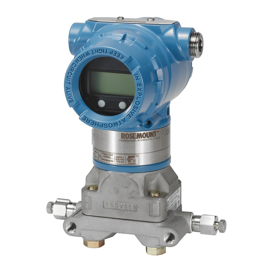
Reference Manual 00809-0100-4101, Rev AA Rosemount 2051 July 2008 MODELS COVERED The following Rosemount 2051 Pressure Transmitters are covered by this manual: ™ Rosemount 2051C Coplanar Pressure Transmitter 2051CD - Differential Pressure Transmitter Measures differential pressure up to 2000 psi (137,9 bar) -
Page 11: Transmitter Overview
Rosemount 2051 July 2008 TRANSMITTER The Rosemount 2051C Coplanar design is offered for Differential Pressure (DP) and Gage Pressure (GP) measurements where it utilizes Emerson OVERVIEW Process Management capacitance sensor technology. Piezoresistive sensor technology is utilized in the Rosemount 2051T measurements. - Page 12 Reference Manual 00809-0100-4101, Rev AA Rosemount 2051 July 2008...
-
Page 13: Overview
OVERVIEW The information in this section covers installation considerations for the Rosemount 2051 with HART protocols. A Quick Installation Guide for HART protocol (document number 00825-0100-4101) is shipped with every transmitter to describe basic pipe-fitting and wiring procedures for initial installation. -
Page 14: Warnings
Management for use as spare parts could reduce the pressure retaining capabilities of the transmitter and may render the instrument dangerous. • Use only bolts supplied or sold by Emerson Process Management as spare parts. • Refer to page A-25 for a complete list of spare parts. -
Page 15: Mechanical Considerations
Reference Manual 00809-0100-4101, Rev AA Rosemount 2051 July 2008 MECHANICAL NOTE For steam service or for applications with process temperatures greater than CONSIDERATIONS the limits of the transmitter, do not blow down impulse piping through the transmitter. Flush lines with the blocking valves closed and refill lines with water before resuming measurement. -
Page 16: Hart Installation Flowchart
Reference Manual 00809-0100-4101, Rev AA Rosemount 2051 July 2008 HART INSTALLATION FLOWCHART Figure 2-1. HART Installation Flowchart START HERE Bench Calibration? Field Install Configure Security and Alarm Configure Verify (page 2-23) Mount Transmitter Set Units Review (page 2-12) Transmitter (page 3-9) -
Page 17: Installation Procedures
Reference Manual 00809-0100-4101, Rev AA Rosemount 2051 July 2008 INSTALLATION PROCEDURES Dimensional Drawings 2051C Coplanar Flange Dimensional Drawing 5.00 (127) 4.36 (111) 3.85 (98) 7.03 (179) 6.40 (163) 2051C Coplanar with Rosemount 305 Coplanar Integral Manifold 5.00 (127) 3.85 (98) 4.36 (111) - Page 18 Reference Manual 00809-0100-4101, Rev AA Rosemount 2051 July 2008 Coplanar Flange Mounting Configurations with Optional Bracket (B4) for 2-in. Pipe or Panel Mounting 2.82 4.36 Bolts (72) (111) for Panel Mounting 2.8 (71) 2.18 (Not Supplied) (55) 7.03 –16 × 1...
- Page 19 Reference Manual 00809-0100-4101, Rev AA Rosemount 2051 July 2008 2051C Coplanar with Traditional Flange 3.85 (98) 5.00 (127) 4.36 (111) 7.76 (197) - 14 NPT Flange Adapter (optional) Drain/ Vent Valve 1.626 (41,3) 2.126 3.40 (86) 1.05 (27) 1.10 (28)
- Page 20 Reference Manual 00809-0100-4101, Rev AA Rosemount 2051 July 2008 Traditional Flange Mounting Configurations with Optional Brackets for 2-in. Pipe or Panel Mounting Panel Mount (Bracket Option B2 / B8) Pipe Mount (Bracket Option B3 / B9 / BC) 9.18 (233) 2.62...
- Page 21 Reference Manual 00809-0100-4101, Rev AA Rosemount 2051 July 2008 2051T Dimensional Drawings 5.00 (127) 3.85 (98) 4.36 (111) 7.15 (182) 2051T with Rosemount 306 Integral Manifold 5.00 (127) 3.85 (98) 4.36 (111) 7.15 (182) 4.85 4.10 (123) (105) 6.25 (159)
- Page 22 Reference Manual 00809-0100-4101, Rev AA Rosemount 2051 July 2008 2051T Typical Mounting Configurations with Optional Mounting Bracket Pipe Mounting Panel Mounting 3.85 (98) 5.16 (131) 1.99 (51) 2.81 (71) 6.21 (158) 3.49 (89) 4.72 (120) 6.90 (175) 2-10...
- Page 23 Reference Manual 00809-0100-4101, Rev AA Rosemount 2051 July 2008 2051L Liquid Level 2-in. Flange Configuration (Flush Mount Only) 3- and 4-in. Flange Configuration 3.85 3.85 (98) (98) 2-in., 4-in., or 6-in. Extension (50.8, 101.6, 152.4) Optional Flushing Connection Ring 5.00 (Lower Housing) (127) 4.36...
-
Page 24: Mount The Transmitter
Reference Manual 00809-0100-4101, Rev AA Rosemount 2051 July 2008 Table 2-1. 2051L Dimensional Specifications Except where indicated, dimensions are in inches (millimeters). Pipe Flange Bolt Circle Outside No. of Bolt Hole Extension O.D. Gasket Class Size Thickness A Diameter B... - Page 25 Rosemount 2051 July 2008 Mounting Brackets Rosemount 2051 Transmitters may be panel-mounted or pipe-mounted through an optional mounting bracket. Refer to Table 2-2 for the complete offering and see Figure 2-2 through Figure 2-5 on pages 2-13 and 2-14 for dimensions and mounting configurations.
- Page 26 Reference Manual 00809-0100-4101, Rev AA Rosemount 2051 July 2008 Figure 2-3. Mounting Bracket Option Codes B1, B7, and BA 1.63 (41) 4.09 (104) 3.75 (95) 2.73 (69) 4.97 (126) 2.81 (71) Figure 2-4. Panel Mounting Bracket Option Codes B2 and B8 Mounting Holes 1.63 (41)
- Page 27 A and M. Bolt Installation Only use bolts supplied with the 2051 or provided by Emerson Process Management as spare parts. When installing the transmitter to one of the optional mounting brackets, torque the bolts to 125 in-lb. (0,9 N-m). Use the following bolt installation procedure: 1.
- Page 28 Reference Manual 00809-0100-4101, Rev AA Rosemount 2051 July 2008 Figure 2-6. Traditional Flange Bolt Configurations DIFFERENTIAL TRANSMITTER GAGE TRANSMITTER Drain/Vent Plug Drain/Vent Drain/Vent 1.75 (44) × 4 1.75 (44) × 4 1.50 (38) × 2 1.50 (38) × 4 NOTE Dimensions are in inches (millimeters).
-
Page 29: Impulse Piping
Reference Manual 00809-0100-4101, Rev AA Rosemount 2051 July 2008 Impulse Piping The piping between the process and the transmitter must accurately transfer the pressure to obtain accurate measurements. There are six possible sources of impulse piping error: pressure transfer, leaks, friction loss (particularly if purging is used), trapped gas in a liquid line, liquid in a gas line, and density variations between the legs. - Page 30 Reference Manual 00809-0100-4101, Rev AA Rosemount 2051 July 2008 Mounting Requirements Impulse piping configurations depend on specific measurement conditions. Refer to Figure 2-8 for examples of the following mounting configurations: Liquid Flow Measurement • Place taps to the side of the line to prevent sediment deposits on the process isolators.
-
Page 31: Process Connections
Reference Manual 00809-0100-4101, Rev AA Rosemount 2051 July 2008 Process Connections Coplanar or Traditional Process Connection Install and tighten all four flange bolts before applying pressure, or process leakage will result. When properly installed, the flange bolts will protrude through the top of the sensor module housing. Do not attempt to loosen or remove the flange bolts while the transmitter is in service. - Page 32 Reference Manual 00809-0100-4101, Rev AA Rosemount 2051 July 2008 O-rings: The two styles of Rosemount flange adapters (Rosemount 1151 and Rosemount 3051/2051/2024/3095) each require a unique O-ring (see Figure 2-9). Use only the O-ring designed for the corresponding flange adaptor.
-
Page 33: Housing Rotation
Reference Manual 00809-0100-4101, Rev AA Rosemount 2051 July 2008 Inline Process Connection Do not apply torque directly to the sensor module. Rotation between the sensor module and the process connection can damage the electronics. To avoid damage, apply torque only to the hex-shaped process connection. -
Page 34: Lcd Display
Configure Security and Security (Write Protect) Alarm There are three security methods with the Rosemount 2051 transmitter: Security Jumper: prevents all writes to transmitter configuration. Local Keys (Local Zero and Span) Software Lock Out: prevents changes to transmitter range points via local zero and span adjustment keys. - Page 35 Reference Manual 00809-0100-4101, Rev AA Rosemount 2051 July 2008 If the transmitter write protection jumper is in the “ON” position, the transmitter will not accept any “writes” to its memory. Configuration changes, such as digital trim and reranging, cannot take place when the transmitter security is...
- Page 36 Reference Manual 00809-0100-4101, Rev AA Rosemount 2051 July 2008 Figure 2-12. Electronics Board 4-20 mA HART Without LCD Meter With LCD Display Alarm Security Figure 2-13. Low Power Transmitter Electronics Boards 1-5 Vdc HART Low Power Without LCD Meter With LCD Display...
-
Page 37: Electrical Considerations
Reference Manual 00809-0100-4101, Rev AA Rosemount 2051 July 2008 ELECTRICAL NOTE Make sure all electrical installation is in accordance with national and local CONSIDERATIONS code requirements. Conduit Installation If all connections are not sealed, excess moisture accumulation can damage the transmitter. -
Page 38: Wiring
Reference Manual 00809-0100-4101, Rev AA Rosemount 2051 July 2008 Wiring Do not connect the power signal wiring to the test terminals. Voltage may burn out the reverse-polarity protection diode in the test connection. NOTE Use shielded twisted pairs to yield best results. To ensure proper communication, use 24 AWG or larger wire, and do not exceed 5000 feet (1500 meters). - Page 39 Reference Manual 00809-0100-4101, Rev AA Rosemount 2051 July 2008 Perform the following procedure to make wiring connections: 1. Remove the housing cover on terminal compartment side. Do not remove the cover in explosive atmospheres when the circuit is live. Signal wiring supplies all power to the transmitter.
-
Page 40: Transient Protection Terminal Block
Reference Manual 00809-0100-4101, Rev AA Rosemount 2051 July 2008 Transient Protection The transmitter will withstand electrical transients of the energy level usually encountered in static discharges or induced switching transients. However, Terminal Block high-energy transients, such as those induced in wiring from nearby lightning strikes, can damage the transmitter. -
Page 41: Grounding
FIELD TERMINALS side of the electronics housing. This screw is identified by a ground symbol ( ). The ground connection screw is standard on all Rosemount 2051 transmitters. Refer to Figure 2-20. • External Ground Assembly: This assembly is included with the optional transient protection terminal block (Option Code T1), and it is included with various hazardous location certifications. - Page 42 Reference Manual 00809-0100-4101, Rev AA Rosemount 2051 July 2008 Figure 2-20. Internal Ground Screw Internal Ground Connection Screw Figure 2-21. External Ground Assembly External Ground Assembly NOTE Grounding the transmitter case via threaded conduit connection may not provide sufficient ground continuity.
-
Page 43: Hazardous Locations Certifications
Reference Manual 00809-0100-4101, Rev AA Rosemount 2051 July 2008 HAZARDOUS Individual transmitters are clearly marked with a tag indicating the approvals they carry. Transmitters must be installed in accordance with all applicable LOCATIONS codes and standards to maintain these certified ratings. Refer to “Hazardous CERTIFICATIONS Locations Certifications”... -
Page 44: Rosemount 305 Integral Manifold Installation Procedure
Reference Manual 00809-0100-4101, Rev AA Rosemount 2051 July 2008 Rosemount 305 Integral To install a 305 Integral Manifold to a 2051 transmitter: Manifold Installation 1. Inspect the PTFE sensor module o-rings. Undamaged o-rings may be Procedure reused. If the o-rings are damaged (if they have nicks or cuts, for example), replace with o-rings designed for Rosemount transmitter. -
Page 45: Integral Manifold Operation
Reference Manual 00809-0100-4101, Rev AA Rosemount 2051 July 2008 Integral Manifold Operation Three-valve configuration shown. In normal operation the two isolate valves between the process and instrument ports will be open and the equalizing valve(s) will be closed. Drain/ Drain/... - Page 46 Reference Manual 00809-0100-4101, Rev AA Rosemount 2051 July 2008 The manifold valves are now in the proper configuration for zeroing the transmitter. To return the transmitter to Drain/ service, close the equalizing valve(s) first. Drain/ Vent Vent Valve Valve Equalize...
-
Page 47: Liquid Level Measurement
Reference Manual 00809-0100-4101, Rev AA Rosemount 2051 July 2008 LIQUID LEVEL Differential pressure transmitters used for liquid level applications measure hydrostatic pressure head. Liquid level and specific gravity of a liquid are MEASUREMENT factors in determining pressure head. This pressure is equal to the liquid height above the tap multiplied by the specific gravity of the liquid. - Page 48 Reference Manual 00809-0100-4101, Rev AA Rosemount 2051 July 2008 Wet Leg Condition Condensation of the gas above the liquid slowly causes the low side of the transmitter piping to fill with liquid. The pipe is purposely filled with a convenient reference fluid to eliminate this potential error. This is a wet leg condition.
- Page 49 Reference Manual 00809-0100-4101, Rev AA Rosemount 2051 July 2008 Bubbler System in Open Vessel A bubbler system that has a top-mounted pressure transmitter can be used in open vessels. This system consists of an air supply, pressure regulator, constant flow meter, pressure transmitter, and a tube that extends down into the vessel.
- Page 50 Reference Manual 00809-0100-4101, Rev AA Rosemount 2051 July 2008 2-38...
-
Page 51: Overview
Reference Manual 00809-0100-4101, Rev AA Rosemount 2051 July 2008 Section 3 Configuration Overview ........page 3-1 Safety Messages . -
Page 52: Commissioning
Reference Manual 00809-0100-4101, Rev AA Rosemount 2051 July 2008 COMMISSIONING Commissioning consists of testing the transmitter and verifying transmitter configuration data. The 2051 transmitters can be commissioned either before or after installation. Commissioning the transmitter on the bench before installation using a HART Communicator or AMS Device Manager ensures that all transmitter components are in working order. -
Page 53: Wiring Diagrams
Reference Manual 00809-0100-4101, Rev AA Rosemount 2051 July 2008 Wiring Diagrams Connect the equipment as shown in Figure 3-1 for 4-20 mA HART or Figure 3-2 for 1-5 Vdc HART Low Power. To ensure successful communication, a resistance of at least 250 ohms must be present between the HART Communicator loop connection and the power supply. -
Page 54: Configuration Data Review
Reference Manual 00809-0100-4101, Rev AA Rosemount 2051 July 2008 CONFIGURATION DATA NOTE Information and procedures in this section that make use of HART REVIEW Communicator fast key sequences and AMS Device Manager assume that the transmitter and communication equipment are connected, powered, and operating correctly. -
Page 55: Hart Communicator Menu Trees
Reference Manual 00809-0100-4101, Rev AA Rosemount 2051 July 2008 HART COMMUNICATOR 2051 HART menu tree for 4-20 mA HART output MENU TREES Online Menu 1 PROCESS 1 Keypad Input 1 Pressure VARIABLE 2 Apply Values 2 Percent Range 1 DEVICE... - Page 56 Reference Manual 00809-0100-4101, Rev AA Rosemount 2051 July 2008 2051 HART menu tree for 1-5 Vdc HART Low Power Online Menu 1 PROCESS 1 Pressure 1 Self Test VARIABLE 2 Percent Range 2 Status 1 Keypad Input 1 DEVICE 3 Analog Output...
-
Page 57: Fast Key Sequence
Reference Manual 00809-0100-4101, Rev AA Rosemount 2051 July 2008 FAST KEY SEQUENCE A check ( ) indicates the basic configuration parameters. At minimum, these parameters should be verified as part of the configuration and startup procedure. Table 3-1. 2051 Fast Key... -
Page 58: Check Output
Reference Manual 00809-0100-4101, Rev AA Rosemount 2051 July 2008 CHECK OUTPUT Before performing other transmitter on-line operations, review the digital output parameters to ensure that the transmitter is operating properly and is configured to the appropriate process variables. Process Variables The process variables for the 2051 provide transmitter output, and are continuously updated. -
Page 59: Basic Setup
Reference Manual 00809-0100-4101, Rev AA Rosemount 2051 July 2008 BASIC SETUP Set Process Variable The PV Unit command sets the process variable units to allow you to monitor your process using the appropriate units of measure. Units HART Communicator 4-20 mA Fast Keys... -
Page 60: Rerange
Range & Sensor limits, refer to “Range and Sensor Limits” on page A-4. NOTE Transmitters are shipped from Emerson Process Management fully calibrated per request or by the factory default of full scale (zero to upper range limit). NOTE Regardless of the range points, the 2051 will measure and report all readings within the digital limits of the sensor. - Page 61 Reference Manual 00809-0100-4101, Rev AA Rosemount 2051 July 2008 Select from one of the methods below to rerange the transmitter. Each method is unique; examine all options closely before deciding which method works best for your process. • Rerange with a HART Communicator or AMS Device Manager only.
- Page 62 Reference Manual 00809-0100-4101, Rev AA Rosemount 2051 July 2008 Rerange with a Pressure Input Source and a HART Communicator or AMS Device Manager Reranging using the HART Communicator and applied pressure is a way of reranging the transmitter when specific 4 and 20 mA points (1 and 5 Vdc points) are not calculated.
-
Page 63: Damping
Reference Manual 00809-0100-4101, Rev AA Rosemount 2051 July 2008 To rerange the transmitter using the span and zero buttons, perform the following procedure: 1. Loosen the screw holding the certifications label on the side of the transmitter housing. Slide the label to expose the zero and span buttons. -
Page 64: Lcd Display
Reference Manual 00809-0100-4101, Rev AA Rosemount 2051 July 2008 HART Communicator 4-20 mA Fast Keys 1, 3, 6 1-5 Vdc Fast Keys 1, 3, 6 AMS Device Manager Right click on the device and select “Configure” from the menu. 1. In the “Basic Setup” tab, enter the damping value in the “Damp” field, click Apply. -
Page 65: Lcd Display Configuration For 4-20 Ma Hart Only
Reference Manual 00809-0100-4101, Rev AA Rosemount 2051 July 2008 LCD Display The factory default alternates are between Engineering Units and % of Range. The LCD Display Configuration command allows customization of the Configuration for 4-20 LCD display to suit application requirements. The LCD display will alternate... -
Page 66: Detailed Setup
Reference Manual 00809-0100-4101, Rev AA Rosemount 2051 July 2008 a. Select 1 Sel dec pt pos. Choose the decimal point representation that will provide the most accurate output for your application. For example, when outputting between 0 and 75 GPM, choose XX.XXX or use the decimal point examples below:... -
Page 67: Alarm And Saturation Levels For Burst Mode
Reference Manual 00809-0100-4101, Rev AA Rosemount 2051 July 2008 Table 3-3. NAMUR-Compliant Alarm and Saturation Values Level 4–20 mA Saturation 4–20 mA Alarm ≤ 3.6 mA 3.8 mA ≥ 22.5 mA High 20.5 mA Table 3-4. 1-5 Vdc HART Low-Power Alarm and... -
Page 68: Alarm Level Verification
Reference Manual 00809-0100-4101, Rev AA Rosemount 2051 July 2008 Saturation: • Primary variable is sent normally • Temperature is sent normally Alarm Level Verification If the transmitter electronics board, sensor module, or LCD display is repaired or replaced, verify the transmitter alarm level before returning the transmitter to service. - Page 69 Reference Manual 00809-0100-4101, Rev AA Rosemount 2051 July 2008 1. a. For 4-20 mA HART output, connect a reference meter to the transmitter by either connecting the meter to the test terminals on the terminal block, or shunting transmitter power through the meter at some point in the loop.
-
Page 70: Advanced Functions
Reference Manual 00809-0100-4101, Rev AA Rosemount 2051 July 2008 After completing the test procedure, the display returns to the loop test screen to choose another output value or to end loop testing. 6. Select End and click Next to end loop testing. - Page 71 Reference Manual 00809-0100-4101, Rev AA Rosemount 2051 July 2008 11. Select 3: Send to download the configuration to the transmitter. 12. Select OK after the control loop is set to manual. 13. After the configuration has been sent, select OK to acknowledge that the loop can be returned to automatic control.
-
Page 72: Burst Mode
Reference Manual 00809-0100-4101, Rev AA Rosemount 2051 July 2008 To apply a user configuration perform the following procedure: 1. Select the desired user configuration in the User Configurations window. 2. Drag the icon onto a like device in AMS Device Manager Explorer or Device Connection View. -
Page 73: Multidrop Communication
Reference Manual 00809-0100-4101, Rev AA Rosemount 2051 July 2008 MULTIDROP Multidropping transmitters refers to the connection of several transmitters to a single communications transmission line. Communication between the host COMMUNICATION and the transmitters takes place digitally with the analog output of the transmitters deactivated. -
Page 74: Changing A Transmitter Address
Reference Manual 00809-0100-4101, Rev AA Rosemount 2051 July 2008 Changing a Transmitter To activate multidrop communication, the transmitter poll address must be assigned a number from 1 to 15, and each transmitter in a multidropped loop Address must have a unique poll address. -
Page 75: Overview
Sensor Trim ........page 4-10 OVERVIEW This section contains information on calibrating and diagnostics messages on the Rosemount 2051 Pressure Transmitters. HART Communicator and AMS instructions are given to perform configuration functions. For convenience, HART Communicator fast key sequences are labeled “Fast Keys”... -
Page 76: Calibration Overview
Reference Manual 00809-0100-4101, Rev AA Rosemount 2051 July 2008 CALIBRATION Calibration is defined as the process required to optimize transmitter accuracy over a specific range by adjusting the factory sensor characterization curve OVERVIEW located in the microprocessor. Possible procedures are: •... - Page 77 Reference Manual 00809-0100-4101, Rev AA Rosemount 2051 July 2008 Figure 4-1. Transmitter Data Flow with Calibration Options Transmitter Ranged 0 to 100 inH (0 to 0,25 bar) MICRO SENSOR (STEP 2) (STEP 4) (STEP 3) (STEP 1) Output: 100 in. H Output: 20.00 mA...
-
Page 78: Determining Calibration Frequency
Reference Manual 00809-0100-4101, Rev AA Rosemount 2051 July 2008 Determining Calibration Calibration frequency can vary greatly depending on the application, performance requirements, and process conditions. Use the following Frequency procedure to determine calibration frequency that meets the needs of your application. - Page 79 Reference Manual 00809-0100-4101, Rev AA Rosemount 2051 July 2008 Sample Calculation for 2051C with P8 option (0.065% accuracy & 5-year stability) Step 1: Determine the performance required for your application. Required Performance: 0.30% of span Step 2: Determine the operating conditions.
-
Page 80: Choosing A Trim Procedure
Reference Manual 00809-0100-4101, Rev AA Rosemount 2051 July 2008 Choosing a Trim To decide which trim procedure to use, you must first determine whether the analog-to-digital section or the digital-to-analog section of the transmitter Procedure electronics need calibration. Refer to Figure 4-1 and perform the following procedure: 1. -
Page 81: Analog Output Trim
Reference Manual 00809-0100-4101, Rev AA Rosemount 2051 July 2008 ANALOG OUTPUT TRIM The Analog Output Trim commands allow you to adjust the transmitter’s current output at the 4 and 20 mA (1 and 5 Vdc) points to match the plant standards. -
Page 82: Digital-To-Analog Trim Using Other Scale
Reference Manual 00809-0100-4101, Rev AA Rosemount 2051 July 2008 Right click on the device and select “Calibrate,” then “D/A Trim” from the menu 1. Click Next after setting the control loop to manual. 2. Click Next after connecting the reference meter. -
Page 83: Recall Factory Trim-Analog Output
Reference Manual 00809-0100-4101, Rev AA Rosemount 2051 July 2008 1. Click Next after setting the control loop to manual. 2. Select Change to change scale, click Next. 3. Enter Set scale-Lo output value, click Next. 4. Enter Set scale-Hi output value, click Next. -
Page 84: Sensor Trim
Reference Manual 00809-0100-4101, Rev AA Rosemount 2051 July 2008 SENSOR TRIM Sensor Trim Overview Trim the sensor using either sensor or zero trim functions. Trim functions vary in complexity and are application-dependent. Both trim functions alter the transmitter’s interpretation of the input signal. -
Page 85: Sensor Trim
Reference Manual 00809-0100-4101, Rev AA Rosemount 2051 July 2008 HART Communicator 4-20 mA Fast Keys 1, 2, 3, 3, 1 1-5 Vdc Fast Keys 1, 2, 3, 3, 1 Calibrate the sensor with a HART Communicator using the zero trim function as follows: 1. -
Page 86: Recall Factory Trim-Sensor Trim
Reference Manual 00809-0100-4101, Rev AA Rosemount 2051 July 2008 NOTE Select pressure input values so that lower and upper values are equal to or outside the 4 and 20 mA (1 and 5 Vdc) points. Do not attempt to obtain reverse output by reversing the high and low points. -
Page 87: Compensating For Line Pressure
00809-0100-4101, Rev AA Rosemount 2051 July 2008 Compensating for Rosemount 2051 Range 4 and 5 pressure transmitters require a special calibration procedure when used in differential pressure applications. The Line Pressure purpose of this procedure is to optimize transmitter performance by reducing the effect of static line pressure in these applications. - Page 88 Reference Manual 00809-0100-4101, Rev AA Rosemount 2051 July 2008 Low Trim Value LT = LRV - (S/100 x P/1000 x LRV) Where: LT = Corrected Low Trim Value LRV = Lower Range Value Span shift per specification (as a percent of reading)
-
Page 89: Overview
Reference Manual 00809-0100-4101, Rev AA Rosemount 2051 July 2008 Section 5 Troubleshooting Overview ........page 5-1 Safety Messages . - Page 90 Reference Manual 00809-0100-4101, Rev AA Rosemount 2051 July 2008 Table 5-1. Rosemount 2051 Troubleshooting Table for 4-20 mA output Symptom Corrective Actions Transmitter milliamp reading is zero Verify power is applied to signal terminals Check power wires for reversed polarity Verify terminal voltage is 10.5 to 42.4 Vdc...
-
Page 91: Diagnostic Messages
Reference Manual 00809-0100-4101, Rev AA Rosemount 2051 July 2008 DIAGNOSTIC In addition to the output, the LCD meter displays abbreviated operation, error, and warning messages for troubleshooting the transmitter. Messages appear MESSAGES according to their priority, with normal operating messages appearing last. To determine the cause of a message, use a HART Communicator or AMS to further interrogate the transmitter. - Page 92 Reference Manual 00809-0100-4101, Rev AA Rosemount 2051 July 2008 Press Limit The process variable read by the transmitter is outside of the transmitter’s range. Temp Limit The secondary temperature variable read by the transmitter is outside of the transmitter’s range.
- Page 93 Reference Manual 00809-0100-4101, Rev AA Rosemount 2051 July 2008 LOCAL DSBLD This message appears during reranging with the integral zero and span buttons and indicates that the transmitter local zero and span adjustments have been disabled. The adjustments may have been disabled by the transmitter security jumper on the transmitter circuit board or through software commands from the HART Communicator.
- Page 94 Reference Manual 00809-0100-4101, Rev AA Rosemount 2051 July 2008 Message Description Configuration memory not The configuration stored in memory is incompatible with compatible with connected the device to which a transfer has been requested. device CPU board not initialized ON The electronics board is not initialized.
- Page 95 Reference Manual 00809-0100-4101, Rev AA Rosemount 2051 July 2008 Message Description No temperature updates ON No temperature updates being received from the sensor module. Verify that the sensor module ribbon cable is attached correctly. Or replace the transmitter. No UPLOAD_VARIABLES in ddl There is no menu named “upload_variables”...
-
Page 96: Disassembly Procedures
Reference Manual 00809-0100-4101, Rev AA Rosemount 2051 July 2008 Message Description Value out of range The user-entered value is either not within the range for the given type and size of variable or not within the min/max specified by the device. -
Page 97: Remove The Electronics Board
Reference Manual 00809-0100-4101, Rev AA Rosemount 2051 July 2008 Remove the The transmitter electronics board is located in the compartment opposite the terminal side. To remove the electronics board perform the following Electronics Board procedure: 1. Remove the housing cover opposite the field terminal side. -
Page 98: Reassembly Procedures
Reference Manual 00809-0100-4101, Rev AA Rosemount 2051 July 2008 REASSEMBLY 1. Inspect all cover and housing (non-process wetted) O-rings and replace if necessary. Lightly grease with silicone lubricant to ensure a good seal. PROCEDURES 2. Carefully tuck the cable connector completely inside the internal black cap. -
Page 99: Install The Drain/Vent Valve
Reference Manual 00809-0100-4101, Rev AA Rosemount 2051 July 2008 a. Coplanar Process Flange: • Hold the process flange in place by installing the two alignment screws to finger tightness (screws are not pressure retaining). Do not overtighten as this will affect module-to-flange alignment. - Page 100 Reference Manual 00809-0100-4101, Rev AA Rosemount 2051 July 2008 5-12...
-
Page 101: Performance Specifications
Reference Manual 00809-0100-4101, Rev AA Rosemount 2051 July 2008 Appendix A Reference Data Performance Specifications ..... . . page A-1 Functional Specifications . -
Page 102: Long Term Stability
Reference Manual 00809-0100-4101, Rev AA Rosemount 2051 July 2008 Long Term Stability Models Standard Performance Option, P8 2051C Ranges 2-5 ±0.1% of URL for 2 years ±0.125% of URL for 5 years 2051CD Range 1 ±0.2% of URL for 1 year 2051T Ranges 1-5 ±0.1% of URL for 2 years... -
Page 103: Ambient Temperature Effect Per 50°F (28°C
Reference Manual 00809-0100-4101, Rev AA Rosemount 2051 July 2008 Ambient Temperature Effect per 50°F (28°C) Models Ambient Temperature Effect 2051C Ranges 2-5 ±(0.025% URL + 0.125% span) from 1:1 to 5:1 ±(0.05% URL + 0.25% span) from 5:1 to 100:1 Range 1 ±(0.2% URL + 0.5% span) from 1:1 to 50:1... -
Page 104: Functional Specifications
Reference Manual 00809-0100-4101, Rev AA Rosemount 2051 July 2008 FUNCTIONAL SPECIFICATIONS Range and Sensor Limits 2051CD, 2051CG, 2051L Range and Sensor Limits Lower (LRL) Minimum Span Upper (URL) 2051C Differential 2051C Gage 2051L Differential 2051L Gage 0.5 inH 25 inH –25 inH... - Page 105 Reference Manual 00809-0100-4101, Rev AA Rosemount 2051 July 2008 Load Limitations Maximum loop resistance is determined by the voltage level of the external power supply, as described by: Table A-1. Maximum Loop Resistance = 43.5 * (Power Supply Voltage – 10.5)
-
Page 106: Overpressure Limits
Reference Manual 00809-0100-4101, Rev AA Rosemount 2051 July 2008 LCD Block • Configures the local display. 2 Analog Input Blocks • Processes the measurements for input into other function blocks. The output value is in engineering units or custom and contains a status indicating measurement quality. -
Page 107: Static Pressure Limit
Reference Manual 00809-0100-4101, Rev AA Rosemount 2051 July 2008 2051L Limit is flange rating or sensor rating, whichever is lower (see Table A-2). Table A-2. 2051L Flange Rating Standard Type CS Rating SST Rating ANSI/ASME Class 150 285 psig 275 psig... -
Page 108: Humidity Limits
Reference Manual 00809-0100-4101, Rev AA Rosemount 2051 July 2008 Table A-3. 2051 Process Temperature Limits Inert Fill Sensor 0 to 185 °F (–18 to 85 °C) 2051L High-Side Temperature Limits (Process Fill Fluid) ® Syltherm –100 to 300 °F (–73 to 149 °C) ®... -
Page 109: Physical Specifications
Reference Manual 00809-0100-4101, Rev AA Rosemount 2051 July 2008 PHYSICAL SPECIFICATIONS Electrical Connections –14 NPT, G , and M20 × 1.5 (CM20) conduit. Process Connections 2051C • –18 NPT on 2 -in. centers • –14 NPT and RC on 2-in.(50.8mm), 2 -in. -
Page 110: Non-Wetted Parts For 2051C/T/L
Reference Manual 00809-0100-4101, Rev AA Rosemount 2051 July 2008 Reference Process Connection (Transmitter Low Side) Isolating Diaphragms • 316L SST or Alloy C-276 Reference Flange and Adapter • CF-8M (Cast version of 316 SST, material per ASTM-A743) Non-Wetted Parts for... -
Page 111: Shipping Weights
Reference Manual 00809-0100-4101, Rev AA Rosemount 2051 July 2008 Shipping Weights Table A-4. Transmitter Weights without Options Transmitter lb. (kg) 2051C 4.9 (2,2) 2051L Table A-5 below 2051T 3.1 (1,4) Table A-5. 2051L Weights without Options Flush 2-in. Ext. 4-in. Ext. -
Page 112: Ordering Information
Reference Manual 00809-0100-4101, Rev AA Rosemount 2051 July 2008 ORDERING INFORMATION Model Transmitter Type (Select One) 2051C Pressure Transmitter • • Model Measurement Type Differential • — Gage — • Code Pressure Ranges (Range/Min. Span) 2051CD 2051CG –25 to 25 inH O/0.5 inH... - Page 113 Reference Manual 00809-0100-4101, Rev AA Rosemount 2051 July 2008 Code Options Alternate Process Connection: Flange Traditional Flange, 316 SST, SST Drain/Vent • • Traditional Flange, Cast C-276, Alloy C-276 Drain/Vent • • Traditional Flange, 316 SST, Alloy C-276 Drain/Vent •...
- Page 114 Reference Manual 00809-0100-4101, Rev AA Rosemount 2051 July 2008 (11) CSA FISCO Intrinsically Safe • • (11) IECEx FISCO Intrinsically Safe • • (10) Korea (KOSHA) Instrinsic Safety (consult factory for availability) • • (10) GOST Intrinsically Safe (consult factory for availability) •...
- Page 115 Reference Manual 00809-0100-4101, Rev AA Rosemount 2051 July 2008 (6) Not valid with optional code D9 for RC1/2 Adaptors. (7) Not valid with optional codes DF & D9 for Adaptors. (8) Requires option in the Alternate Process Connection: Flange section.
- Page 116 Reference Manual 00809-0100-4101, Rev AA Rosemount 2051 July 2008 Model Transmitter Type (Select One) 2051T In-Line Pressure Transmitter Model Measurement Type Gage Absolute Code Pressure Ranges (Ranges/ Min. Span) 2051TG 2051TA –14.7 to 30 psi/0.3 psi (–1,01 to 2,1 bar/20,7 mbar) 0 to 30 psia/0.3 psia (0 to 2,1 bar/20,7 mbar)
- Page 117 Reference Manual 00809-0100-4101, Rev AA Rosemount 2051 July 2008 ATEX Intrinsic Safety INMETRO Intrinsic Safety (consult factory for availability) China Intrinsic Safety (consult factory for availability) TIIS Intrinsic Safety (consult factory for availability) FM Intrinsically Safe, Division 2 CSA Intrinsically Safe...
- Page 118 Reference Manual 00809-0100-4101, Rev AA Rosemount 2051 July 2008 Special Certifications Calibration Certificate Material Traceability Certification per EN 10204 3.1.B Prior-use certificate of FMEDA data (11) Surface finish certification for sanitary remote seals Calibration certification and tamper evident seal (11)
- Page 119 Reference Manual 00809-0100-4101, Rev AA Rosemount 2051 July 2008 2051LLT Ordering Inform Model Transmitter Type 2051L Flange-Mounted Liquid Level Transmitter Code Pressure Ranges (Range/Minimum Span) –250 to 250 inH O/2.5 inH O (–0,6 to 0,6 bar/6,2 mbar) –1000 to 1000 inH O/10 inH O (–2,5 to 2,5 bar/25 mbar)
- Page 120 Reference Manual 00809-0100-4101, Rev AA Rosemount 2051 July 2008 Code Process Fill-High Pressure Side Temperature Limits Syltherm® XLT -100 to 300 °F (-73 to 135 °C) D.C. Silicone 704 60 to 400 °F (15 to 205 °C) D.C. Silicone 200 -40 to 400 °F (-40 to 205 °C)
- Page 121 Reference Manual 00809-0100-4101, Rev AA Rosemount 2051 July 2008 India (CCOE) Intrinsic Safety Approval (consult factory for availability) ATEX Flameproof, Intrinsic Safety, Type n, Dust INMETRO Flameproof, Intrinsic Safety, Type n (consult factory for availability) TIIS Flameproof, Intrinsic Safety (consult factory for availability)
-
Page 122: Options
Reference Manual 00809-0100-4101, Rev AA Rosemount 2051 July 2008 OPTIONS Standard Configuration Unless otherwise specified, transmitter is shipped as follows: Engineering Units 2051C: inH O (Ranges 1-3), psi (Ranges 4-5) Engineering Units 2051T: psi (all ranges) Engineering Units 2051L: inH... - Page 123 Reference Manual 00809-0100-4101, Rev AA Rosemount 2051 July 2008 LCD display Digital Meter • 2-Line, 5-Digit LCD for 4-20 mA HART and F fieldbus OUNDATION • 1-Line, 4-Digit LCD for 1-5 Vdc HART Low Power • Direct reading of digital data for higher accuracy •...
- Page 124 Reference Manual 00809-0100-4101, Rev AA Rosemount 2051 July 2008 Rosemount 2051C Traditional Flange Bracket Options Bracket for 2-in. Pipe Mounting • For use with the traditional flange option • Bracket for mounting on 2-in. pipe • Carbon steel construction with carbon steel bolts •...
-
Page 125: Spare Parts
Reference Manual 00809-0100-4101, Rev AA Rosemount 2051 July 2008 SPARE PARTS Terminal Block, HART Part Number 4-20 mA HART Output Standard terminal block assembly 02051-9005-0001 Transient terminal block assembly (option T1) 02051-9005-0002 1-5 Vdc HART Low Power Output Standard terminal block assembly... - Page 126 Reference Manual 00809-0100-4101, Rev AA Rosemount 2051 July 2008 Flanges Part Number Differential Coplanar Flange Nickel-plated carbon steel 03031-0388-0025 316 SST 03031-0388-0022 Cast C-276 03031-0388-0023 Gage Coplanar Flange Nickel-plated carbon steel 03031-0388-1025 316 SST 03031-0388-1022 Cast C-276 03031-0388-1023 Coplanar Flange Alignment Screw (package of 12)
- Page 127 Reference Manual 00809-0100-4101, Rev AA Rosemount 2051 July 2008 Bolt Kits COPLANAR FLANGE Flange Bolt Kit {44 mm (1.75 in.)} (Set of 4) Carbon steel 03031-0312-0001 316 SST 03031-0312-0002 ASTM A 193, Grade B7M 03031-0312-0003 ASTM A 193, Class 2, Grade B8M 03031-0312-0005 Flange/Adapter Bolt Kit {73 mm (2.88 in.)} (Set of 4)
- Page 128 Reference Manual 00809-0100-4101, Rev AA Rosemount 2051 July 2008 A-28...
-
Page 129: Overview
Installation of this transmitter in an explosive environment must be in accordance with the appropriate local, national, and international standards, codes, and practices. Please review this section of the Rosemount 2051 reference manual for any restrictions associated with a safe installation. -
Page 130: European Directive Information
The EC declaration of conformity for all applicable European directives for this product can be found on the Rosemount website at www.rosemount.com. A Information hard copy may be obtained by contacting an Emerson Process Management representative. ATEX Directive (94/9/EC) All 2051 transmitters comply with the ATEX Directive. - Page 131 Reference Manual 00809-0100-4101, Rev AA Rosemount 2051 July 2008 Canadian Standards Association (CSA) E6 Explosion-Proof for Class I, Division 1, Groups B, C, and D. Dust-Ignition-Proof for Class II and Class III, Division 1, Groups E, F, and G. Suitable for Class I, Division 2 Groups A, B, C, and D for indoor and outdoor hazardous locations.
- Page 132 3.The 2051 does not comply with the requirements of IEC 60079-1 Clause 5 for flameproof joints. Contact Emerson Process Management for information on the dimensions of flameproof joints. ND ATEX Dust Certification No.
- Page 133 3.The 2051 does not comply with the requirements of IEC 60079-1 Clause 5 for flameproof joints. Contact Emerson Process Management for information on the dimensions of flameproof joints. N7 IECEx Type n Certification No.
- Page 134 Reference Manual 00809-0100-4101, Rev AA Rosemount 2051 July 2008 GOST Certifications (consult factory for availability) Intrinsic Safety Certificate Pending EM Flame-Proof Certificate Pending China (NEPSI) Certifications (consult factory for availability) E3 Flame-Proof Ex d II B+H T3~T5 Intrinsic Safety Ex ia IIC T3/T4...
-
Page 135: Approval Drawings
Reference Manual 00809-0100-4101, Rev AA Rosemount 2051 July 2008 APPROVAL DRAWINGS Factory Mutual (FM) - Page 136 Reference Manual 00809-0100-4101, Rev AA Rosemount 2051 July 2008...
- Page 137 Reference Manual 00809-0100-4101, Rev AA Rosemount 2051 July 2008...
- Page 138 Reference Manual 00809-0100-4101, Rev AA Rosemount 2051 July 2008 B-10...
- Page 139 Reference Manual 00809-0100-4101, Rev AA Rosemount 2051 July 2008 B-11...
- Page 140 Reference Manual 00809-0100-4101, Rev AA Rosemount 2051 July 2008 B-12...
- Page 141 Reference Manual 00809-0100-4101, Rev AA Rosemount 2051 July 2008 B-13...
- Page 142 Reference Manual 00809-0100-4101, Rev AA Rosemount 2051 July 2008 B-14...
- Page 143 Reference Manual 00809-0100-4101, Rev AA Rosemount 2051 July 2008 B-15...
- Page 144 Reference Manual 00809-0100-4101, Rev AA Rosemount 2051 July 2008 B-16...
- Page 145 Reference Manual 00809-0100-4101, Rev AA Rosemount 2051 July 2008 B-17...
- Page 146 Reference Manual 00809-0100-4101, Rev AA Rosemount 2051 July 2008 B-18...
- Page 147 Reference Manual 00809-0100-4101, Rev AA Rosemount 2051 July 2008 B-19...
-
Page 148: Canadian Standards Association (Csa)
Reference Manual 00809-0100-4101, Rev AA Rosemount 2051 July 2008 Canadian Standards Association (CSA) B-20... - Page 149 Reference Manual 00809-0100-4101, Rev AA Rosemount 2051 July 2008 B-21...
- Page 150 Reference Manual 00809-0100-4101, Rev AA Rosemount 2051 July 2008 B-22...
- Page 151 Reference Manual 00809-0100-4101, Rev AA Rosemount 2051 July 2008 B-23...
- Page 152 Reference Manual 00809-0100-4101, Rev AA Rosemount 2051 July 2008 B-24...
- Page 153 Reference Manual 00809-0100-4101, Rev AA Rosemount 2051 July 2008 B-25...
- Page 154 Reference Manual 00809-0100-4101, Rev AA Rosemount 2051 July 2008 B-26...
- Page 155 Reference Manual 00809-0100-4101, Rev AA Rosemount 2051 July 2008 B-27...
- Page 156 Reference Manual 00809-0100-4101, Rev AA Rosemount 2051 July 2008 B-28...
-
Page 157: Glossary
Reference Manual 00809-0100-4101, Rev AA Rosemount 2051 July 2008 Appendix C Glossary Some of the terms used in this manual relate specifically to the operation of Rosemount transmitters, hand-held HART Communicators, and other Rosemount products. The following list provides brief definitions. See the sections listed for additional information. - Page 158 Reference Manual 00809-0100-4101, Rev AA Rosemount 2051 July 2008 Lower Range Limit (LRL) Lowest value of the measured variable that the transmitter can be configured to measure. Lower Range Value (LRV) Lowest value of the measured variable that the analog output of the transmitter is currently configured to measure.
- Page 159 Reference Manual 00809-0100-4101, Rev AA Rosemount 2051 July 2008 Index Configuration Diagrams ..3-3 Applying a user Bench hook-up Address . . 3-21 ..3-3 .
- Page 160 Reference Manual 00809-0100-4101, Rev AA Rosemount 2051 July 2008 ....3-10 Housing Manual Rerange ... . . 5-9 .
- Page 161 Reference Manual 00809-0100-4101, Rev AA Rosemount 2051 July 2008 Trim ..4-7 Analog output ..4-7 Digital to Analog ..4-8 Other scale .
- Page 162 Reference Manual 00809-0100-4101, Rev AA Rosemount 2051 July 2008 Index-4...
- Page 164 July 2008 Standard Terms and Conditions of Sale can be found at www.rosemount.com\terms_of_sale The Emerson logo is a trade mark and service mark of Emerson Electric Co. Rosemount and the Rosemount logotype are registered trademarks of Rosemount Inc. Coplanar is a trademark of Rosemount Inc.
Need help?
Do you have a question about the Rosemount 2051 and is the answer not in the manual?
Questions and answers