Emerson Rosemount 2051CF Series Quick Start Manual
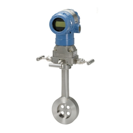
Pressure transmitter with 4–20 ma hart and 1–5 vdc low power hart protocol (revision 5 and 7)
Hide thumbs
Also See for Rosemount 2051CF Series:
- Quick start manual (52 pages) ,
- Quick installation manual (21 pages) ,
- Quick start manual (34 pages)

Related Manuals for Emerson Rosemount 2051CF Series


Summary of Contents for Emerson Rosemount 2051CF Series
- Page 1 Quick Start Guide 00825-0100-4107, Rev FA May 2021 ™ Rosemount 2051 Pressure Transmitter and Rosemount 2051CF Series Flow Meter ® with 4–20 mA HART and 1–5 Vdc Low Power HART Protocol (Revision 5 and 7)
- Page 2 Restrict physical access by unauthorized personnel to protect end users’ assets. This is true for all systems used within the facility. Replacement equipment or spare parts not approved by Emerson for use as spare parts could reduce the pressure retaining capabilities of the transmitter and may render the instrument dangerous.
-
Page 3: Table Of Contents
May 2021 Quick Start Guide WARNING Improper assembly of manifolds to traditional flange can damage sensor module. For safe assembly of manifold to traditional flange, bolts must break back plane of flange web (i.e., bolt hole) but must not contact sensor module housing. Contents System readiness......................... - Page 4 Quick Start Guide May 2021 Emerson.com/Rosemount...
-
Page 5: System Readiness
Emerson.com 00809-0200- Rev 1 Group 4101, Rev BA or DD5: DD FieldComm newer Rev 1 Group Emerson AMS Device Emerson.com Manager V 10.5 or higher: DD Rev 2 Emerson AMS Device Emerson.com Manager V 8 to 10.5: DD Rev 1... - Page 6 (DTM) document (DD) DD4: DD FieldComm Emerson.com 00809-0200- Rev 4 Group 4101, Rev BA DD5: NA Emerson AMS Device Emerson.com Manager V 8 or higher: DD Rev 2 Emerson 375/475: FieldCommun DD Rev 2 icator.com ® Fieldbus device revision can be read using a F...
-
Page 7: Mount The Transmitter
May 2021 Quick Start Guide Mount the transmitter Liquid applications Procedure 1. Place taps to the side of the line. 2. Mount beside or below the taps. 3. Mount the transmitter so the drain/vent valves are oriented upward. Gas applications Procedure 1. - Page 8 Quick Start Guide May 2021 Steam applications Procedure 1. Place taps to the side of the line. 2. Mount beside or below the taps. 3. Fill impulse lines with water. Emerson.com/Rosemount...
- Page 9 May 2021 Quick Start Guide Figure 2-1: Panel and Pipe Mounting Panel mount Pipe mount Coplanar flange Traditional flange Rosemount 2051T × 1 panel bolts are customer supplied. Quick Start Guide...
- Page 10 Use only bolts supplied with the transmitter or sold by Emerson as spare parts. Figure 2-2 illustrates common transmitter assemblies with the bolt length required for proper transmitter assembly.
- Page 11 May 2021 Quick Start Guide 3. Torque the bolts to the final torque value using the same crossing pattern. See Table 2-1 for final torque value. 4. Verify the flange bolts are protruding through the sensor module bolt holes before applying pressure. Table 2-1: Torque Values for the Flange and Flange Adapter Bolts Bolt material Head markings Initial torque Final torque...
- Page 12 360° around the transmitter between the housing and sensor. (See Figure 2-4.) Keep the vent path free of any obstruction, including but not limited to paint, dust, and lubrication by mounting the transmitter so fluids can drain away. Emerson.com/Rosemount...
- Page 13 May 2021 Quick Start Guide Figure 2-4: In-line Gage Low Side Pressure Port A. Pressure port location Quick Start Guide...
-
Page 14: Housing Rotation
3. If the desired location cannot be achieved due to thread limit, rotate the housing counterclockwise to the desired location (up to 360° from thread limit). 4. Retighten the housing rotation set screw to no more than 7 in-lbs when desired location is reached. Emerson.com/Rosemount... -
Page 15: Set The Switches
May 2021 Quick Start Guide Set the switches Set alarm and security switch configuration before installation as shown in Figure 4-1. • The alarm switch sets the analog output alarm to high or low. • Default alarm is high. • The security switch allows ( ) or prevents ( ) any configuration of the transmitter. -
Page 16: Connect The Wiring And Power Up
Shielded twisted pair cable should be used for best results. Use 24 AWG or larger wire that does not exceed 5,000 ft. (1500 m) in length. If applicable, install wiring with a drip loop. Arrange the drip loop so the bottom is lower than the conduit connections and the transmitter housing. Emerson.com/Rosemount... - Page 17 May 2021 Quick Start Guide CAUTION • Installation of the transient protection terminal block does not provide transient protection unless the Rosemount 2051HT case is properly grounded. • Do not run signal wiring in conduit or open trays with power wiring, or near heavy electrical equipment.
- Page 18 Step 1 through Step 8. When the transmitter is properly wired, refer to Figure 5-2 for internal and external transient grounding locations. Note The Rosemount 2051HT polished 316 SST housing only provides ground termination inside the terminal compartment. Emerson.com/Rosemount...
-
Page 19: Verify Configuration
A Rosemount 2051 DD must be installed on the Field Communicator to verify configuration. Fast Key sequences for the latest DD are shown in Table 6-1. For Fast Key sequences using legacy DD's, contact your local Emerson representative. Note Emerson recommends installing the latest DD to access the complete functionality. - Page 20 To activate the LOI, push any button. LOI button functionality is shown on the bottom corners of the display. See Table 6-2 Figure 6-1 for button operation and menu information. Emerson.com/Rosemount...
- Page 21 May 2021 Quick Start Guide Table 6-2: LOI Button Operation Button Left SCROLL Right ENTER Figure 6-1: LOI Menu Assign PV HART Revision Switch HART Revision mode If the HART configuration tool is not capable of communicating with HART Revision 7, the Rosemount 2051 will load a generic menu with limited capability.
- Page 22 Quick Start Guide May 2021 Note Table 6-1 to change HART Revision when the correct device driver is loaded. Emerson.com/Rosemount...
-
Page 23: Trim The Transmitter
May 2021 Quick Start Guide Trim the transmitter Devices are calibrated by the factory. Once installed, it is recommended to perform a zero trim on gage transmitters to eliminate error due to mounting position or static pressure effects. A zero trim can be performed using either a Field Communicator or configuration buttons. - Page 24 To access the configuration buttons on an aluminum housing, loosen the screw on the top tag and slide the tag on the top of the transmitter. Figure 7-1: External or Rear/Terminal-Side Configuration Buttons Analog zero and Digital zero Aluminum span Polished 316 SST Emerson.com/Rosemount...
- Page 25 May 2021 Quick Start Guide A. Configuration buttons LOI buttons (option M4) only offer front facing buttons on SST housing (option 1). Options D4 and DZ can still be purchased for rear/terminal-side facing buttons. Use one of the following procedures to perform a zero trim: 7.2.1 Perform trim with LOI (option M4) Procedure...
-
Page 26: Safety Instrumented Systems
Quick Start Guide May 2021 Safety instrumented systems For safety certified installations, refer to the Rosemount 2051 Reference Manual for installation procedure and system requirements. Emerson.com/Rosemount... -
Page 27: Product Certifications
May 2021 Quick Start Guide Product certifications European Directive Information A copy of the EU Declaration of Conformity can be found at the end of the Quick Start Guide. The most recent revision of the EU Declaration of Conformity can be found at EmersonProcess.com/Rosemount. Ordinary Location Certification As standard, the transmitter has been examined and tested to determine that the design meets the basic electrical, mechanical, and fire protection... - Page 28 Certificate: 2041384 Standards: CAN/CSA C22.2 No. 0-10, CSA Std C22.2 No. 25-1966, CSA Std C22.2 No. 30-M1986, CAN/CSA-C22.2 No. 94-M91, CSA Std C22.2 No.142-M1987, CAN/CSA-C22.2 No.157-92, CSA Std C22.2 No. 213-M1987, CAN/CSA-E60079-0:07, CAN/CSA- E60079-1:07, CAN/CSA-E60079-11-02, CAN/CSA-C22.2 No. 60529:05, ANSI/ISA-12.27.01–2003 Emerson.com/Rosemount...
- Page 29 May 2021 Quick Start Guide Markings: Explosion-Proof for Class I, Divisions 1, Groups B, C, and D. Dust-Ignition Proof for Class II and Class III, Division 1, Groups E, F, and G. Suitable for Class I, Division 2; Groups A, B, C, and D for indoor and outdoor hazardous locations.
- Page 30 ≤ +70 °C) Table 9-2: Input Parameters ® HART Fieldbus/ ® PROFIBUS Voltage U 30 V 30 V Current I 200 mA 300 mA Power P 1.3 W Capacitance C 0.012 μF 0 μF Inductance L 0 mH 0 mH Emerson.com/Rosemount...
- Page 31 May 2021 Quick Start Guide Special Conditions for Safe Use (X): 1. If the equipment is fitted with an optional 90V transient suppressor, it is incapable of withstanding the 500V isolation from earth test and this must be taken into account during installation 2.
- Page 32 Installation, maintenance and use shall take into account the environmental conditions to which the diaphragm shall be subjected. The manufacturer's instructions for installation and maintenance shall be followed in detail to assure safety during its expected lifetime. Emerson.com/Rosemount...
- Page 33 May 2021 Quick Start Guide 2. Appropriate cable, glands and plugs need to be suitable for a temperature of 5 °C greater than maximum specified temperature for location where installed. 3. Flameproof joints are not intended for repair. 4. Non-standard paint options may cause risk from electrostatic discharge.
- Page 34 If fitted with a 90V transient suppressor, the equipment is not capable of withstanding the 500V electrical strength test as defined in clause 6.5.1 of IEC60079-15:2010. This must be taken into account during installation. Brazil E2 INMETRO Flameproof Certificate: UL-BR 14.0375X Emerson.com/Rosemount...
- Page 35 May 2021 Quick Start Guide Standards: ABNT NBR IEC60079-0:2008 + Errata 1:2011, ABNT NBR IEC 60079-1:2009 + Errata 1:2011, ABNT NBR IEC 60079-26:2008 + Errata 1:2009 Markings: Ex db IIC T6…T4 Ga/Gb IP66, T6 (-60 °C ≤T ≤ +70 °C), T4/T5 (-60 °C ≤T ≤...
- Page 36 EPL Ga. China E3 China Flameproof Certificate: GYJ18.1432X; GYJ20.1485X [Flowmeters] Standards: GB3836.1-2010, GB3836.2-2010, GB3836.20-2010-2010 Markings Pressure Transmitter: Ex d IIC Gb, T6~T4 Ga/Gb Flowmeter: Ex d IIC T5/T6 Ga/Gb 二、产品使用注意事项 1. 产品温度组别和使用环境温度之间的关系为: Emerson.com/Rosemount...
- Page 37 May 2021 Quick Start Guide 温度组别 使用环境温度 过程温度 -60 ℃~+70 ℃ -60 ℃~+70 ℃ -60 ℃~+80 ℃ -60 ℃~+80 ℃ -60 ℃~+80 ℃ -60 ℃~+120 ℃ 2. 产品外壳设有接地端子,用户在使用时应可靠接地。 3. 安装现场应不存在对产品外壳有腐蚀作用的有害气体。 4. 现场安装时,电缆引入口须选用经国家指定防爆检验机构检验认 可、具有 Ex dⅡC Gb 防爆等级的电缆引入装置或堵封件,冗余电缆 引入口须用堵封件有效密封。 5. 用于爆炸性气体环境中,现场安装、使用和维护必须严格遵守“严禁 带电开盖!”的警告语。...
- Page 38 0Ex ia IIC T4 Ga X (-60 °C ≤ T ≤ +70 °C) Special Condition for Safe Use (X): See certificate for special conditions. 9.12 Combinations Combination of E1, I1, N1, and ND Combination of E2 and I2 Combination of E5 and I5 Combination of E6 and I6 Emerson.com/Rosemount...
- Page 39 May 2021 Quick Start Guide Combination of E7, I7, N7 and IECEx Dust IECEx Dust Certificate IECEx BAS 08.0058X Standards IEC60079-0:2011, IEC60079-31:2008 Markings Ex tA IIIC T95 °C T500 105 °C Da (–20 °C ≤ T ≤ +85 °C) Special Condition for Safe Use (X): If the equipment is fitted with an optional 90V transient suppressor, it is incapable of withstanding a 500V isolation from earth test and this must be taken into account during installation.
- Page 40 May 2021 Intended Use DNV GL Rules for Classification - Ships and offshore units Application Location classes Type 2051 Temperature Humidity Vibration Enclosure SLL Lloyds Register (LR) Type Approval Certificate 11/60002 Application Environmental categories ENV1, ENV2, ENV3 and ENV5 Emerson.com/Rosemount...
- Page 41 May 2021 Quick Start Guide 9.14 Declaration of conformity Quick Start Guide...
- Page 42 Quick Start Guide May 2021 Emerson.com/Rosemount...
- Page 43 May 2021 Quick Start Guide Quick Start Guide...
- Page 44 Quick Start Guide May 2021 9.15 China RoHS Emerson.com/Rosemount...
- Page 45 May 2021 Quick Start Guide Quick Start Guide...
- Page 46 Quick Start Guide May 2021 Emerson.com/Rosemount...
- Page 47 May 2021 Quick Start Guide Quick Start Guide...
- Page 48 For more information: www.emerson.com © 2021 Emerson. All rights reserved. Emerson Terms and Conditions of Sale are available upon request. The Emerson logo is a trademark and service mark of Emerson Electric Co. Rosemount is a mark of one of the Emerson family of companies.
Need help?
Do you have a question about the Rosemount 2051CF Series and is the answer not in the manual?
Questions and answers