Table of Contents
Advertisement
Quick Links
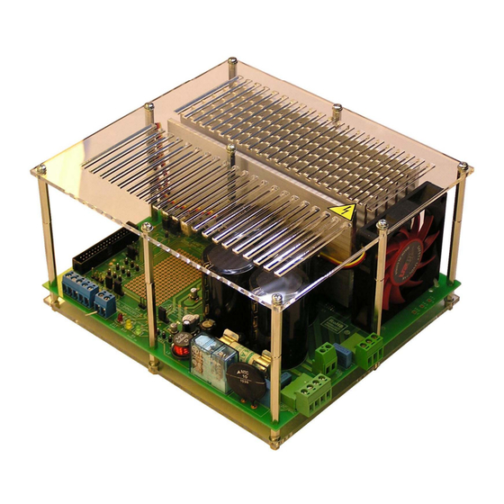
2 kW 3-phase motor control STEVAL-IHM028V1 demonstration board
featuring the IGBT intelligent power module STGIPS20K60
1
Introduction
This document describes the 2 kW 3-phase motor control demonstration board featuring the
IGBT intelligent power module STGIPS20K60. The demonstration board is an AC-DC
inverter that generates a 3-phase waveform for driving 3-phase motors such as induction
motors or permanent magnet synchronous motors (PMSM) up to maximal 2000 W with or
without sensors.
The main device presented in this user manual is a universal, fully evaluated and populated
design consisting of a 3-phase inverter bridge based on the 600 V IGBT power module in
the SDIP 25L package mounted on a heatsink. The IGBT power module integrates all power
IGBT switches with freewheeling diodes together with high voltage gate drivers. Thanks to
this integrated module, the system has been specifically designed to achieve power
inversion in a reliable and compact design. Such integration saves PCB space occupation
and assembly costs, together with high reliability due to the design simplicity.
The board is designed to be compatible with single-phase mains, supplying from 90 VAC to
285 VAC or from 125 VDC up to 400 VDC for the DC voltage.
This document is associated with the release of the STEVAL-IHM028V1 demonstration
board (see
Figure 1.
January 2011
Figure
1).
STEVAL- IHM028V1
Doc ID 18293 Rev 1
UM1036
User manual
www.st.com
1/48
Advertisement
Table of Contents

Related Manuals for STMicroelectronics UM1036


Summary of Contents for STMicroelectronics UM1036
-
Page 1: Introduction
UM1036 User manual 2 kW 3-phase motor control STEVAL-IHM028V1 demonstration board featuring the IGBT intelligent power module STGIPS20K60 Introduction This document describes the 2 kW 3-phase motor control demonstration board featuring the IGBT intelligent power module STGIPS20K60. The demonstration board is an AC-DC... -
Page 2: Table Of Contents
Contents UM1036 Contents Introduction ..........1 System introduction . - Page 3 UM1036 Contents Connector placement ........34 Bill of materials .
- Page 4 List of tables UM1036 List of tables Table 1. Gain settings for FOC current reading configuration ......20 Table 2.
- Page 5 UM1036 List of figures List of figures Figure 1. STEVAL- IHM028V1 ............1 Figure 2.
-
Page 6: System Introduction
System introduction UM1036 System introduction Main characteristics The information listed below shows the converter specification data and the main parameters set for the STEVAL-IHM028V1 demonstration board. ● Minimum input voltage 125 VDC or 90 VAC ● Maximum input voltage 400 VDC or 285 VAC ●... -
Page 7: Safety And Operating Instructions
UM1036 System introduction Safety and operating instructions 2.3.1 General terms Warning: During assembly, testing, and normal operation, the demonstration board poses several inherent hazards, including bare wires, moving or rotating parts, and hot surfaces. There is a danger of serious personal injury and damage to property if the kit or components are improperly used or installed incorrectly. -
Page 8: Electrical Connections
System introduction UM1036 2.3.4 Electrical connections Applicable national accident prevention rules must be followed when working on the main power supply. The electrical installation must be carried out in accordance with the appropriate requirements. A system architecture which supplies power to the demonstration board must be equipped with additional control and protective devices in accordance with the applicable safety requirements (e. -
Page 9: Board Description
UM1036 Board description Board description System architecture A generic motor control system can be basically schematized as the arrangement of four main blocks (see Figure ● Control block - its main task is to accept user commands and motor drive configuration parameters. -
Page 10: Board Schematic
Board description UM1036 Board schematic Figure 3. STEVAL- IHM028V1 schematic - part 1 10/48 Doc ID 18293 Rev 1... -
Page 11: Figure 4. Steval- Ihm028V1 Schematic - Part 2
UM1036 Board description Figure 4. STEVAL- IHM028V1 schematic - part 2 Doc ID 18293 Rev 1 11/48... -
Page 12: Figure 5. Steval- Ihm028V1 Schematic - Part 3
Board description UM1036 Figure 5. STEVAL- IHM028V1 schematic - part 3 12/48 Doc ID 18293 Rev 1... -
Page 13: Figure 6. Steval- Ihm028V1 Schematic - Part 4
UM1036 Board description Figure 6. STEVAL- IHM028V1 schematic - part 4 Doc ID 18293 Rev 1 13/48... -
Page 14: Figure 7. Steval- Ihm028V1 Schematic - Part 5
Board description UM1036 Figure 7. STEVAL- IHM028V1 schematic - part 5 14/48 Doc ID 18293 Rev 1... -
Page 15: Figure 8. Steval- Ihm028V1 Schematic - Part 6
UM1036 Board description Figure 8. STEVAL- IHM028V1 schematic - part 6 Doc ID 18293 Rev 1 15/48... -
Page 16: Circuit Description
Board description UM1036 Circuit description 3.3.1 Power supply The power supply for the STEVAL-IHM028V1 demonstration board is implemented as a wide range converter. The range of the input voltage is from 90 VAC or 125 VDC up to 285 VAC or 400 VDC. This range allows the demonstration board to be used in direct connection with various single phases as well as the PFC input stage. -
Page 17: Inrush Limitation
UM1036 Board description 3.3.2 Inrush limitation The input stage of the demonstration board is provided with an NTC resistor to eliminate input inrush current peak during the charging of the bulk capacitors. To achieve a higher efficiency of the inverter it is possible to bypass the NTC after the start-up phase. The NTC bypass signal is provided from the MCU board through the J2 connector. -
Page 18: Current Sensing Amplifying Network
Board description UM1036 Overcurrent protection acts as soon as the voltage on the CIN pin rises above the internal voltage reference (typical value V is 0.53 V). Considering the default value of the REF_INT OCP shunt resistor, it follows that the maximum allowed current is equal to: Equation 1 ×... - Page 19 UM1036 Board description Configuration with a shunt resistor, where voltage amplified with an operational amplifier is sensed, was chosen as current sensing networks. Single-shunt configuration requires a single op amp, three-shunt configuration requires three op amps. For compatibility purposes, one of them is common to both basic configurations.
-
Page 20: Table 1. Gain Settings For Foc Current Reading Configuration
Board description UM1036 With the default values this gives: ● = 1.57 V BIAS ● Maximal voltage of V = 1.56 V SIGN ● G = 5.38 ● = 3.90 ● Maximum current amplifiable without distortion is 16 A. Figure 11. Configuration for FOC Table 1 shows the mentioned setting of gain jumpers for both FOC configurations. - Page 21 UM1036 Board description The op amp is used in follower mode with gain of the op amp set by resistors: Equation 5 × 2 --------------------------------------- - ----------- - It is possible to calculate the voltage on the op amp output OP OUT - V...
-
Page 22: The Tachometer And Hall/Encoder Inputs
Board description UM1036 Figure 12. Six-step current sensing configuration Table 2 shows the mentioned setting of gain jumpers for this configuration. Table 2. Gain settings for six-step current reading configuration Setting for six-step configuration Single-shunt configuration Not present Not present... -
Page 23: Active Heatsink Cooling
UM1036 Board description sensed through an NTC resistor RT1. The measured signal is amplified with an operational amplifier and then fed through the J2 motor connector to the MCU control unit to be read with an A-D converter. The signal is also fed to the U9A comparator where it is compared with a 2.5 V reference voltage. -
Page 24: Figure 14. Thermal Resistance Of The Heatsink With Continuous Fan Cooling
Board description UM1036 Figure 14. Thermal resistance of the heatsink with continuous fan cooling 24/48 Doc ID 18293 Rev 1... -
Page 25: Hardware Setting Of The Steval-Ihm028V1
Hardware setting of the STEVAL-IHM028V1 The STEVAL-IHM028V1 demonstration board can be driven through the J2 motor connector by various STMicroelectronics MCU control units which feature a unified 34-pin motor connector. The demonstration board is suitable for field oriented control as well as for tachometer or Hall sensor closed-loop control. -
Page 26: Hardware Settings For Foc In Three-Shunt Configuration
Hardware setting of the STEVAL-IHM028V1 UM1036 Table 3. Jumper settings for PMSM or generic AC motor - six-step Jumper Settings for six-step current control A position for V = 3.3 V B position for V = 5 V A position for software brake... -
Page 27: Hardware Settings For Foc In Single-Shunt Configuration
UM1036 Hardware setting of the STEVAL-IHM028V1 Table 4. Jumper settings for PMSM or generic AC motor - FOC in three-shunt Jumper Settings for FOC in three-shunt A position for V = 3.3 V B position for V = 5 V... -
Page 28: Table 5. Jumper Settings For Pmsm Or Generic Ac Motor - Foc In Single-Shunt
Hardware setting of the STEVAL-IHM028V1 UM1036 Table 5. Jumper settings for PMSM or generic AC motor - FOC in single-shunt Jumper Settings for FOC in single-shunt A position for V = 3.3 V B position for V = 5 V... -
Page 29: Testing Of The Demonstration Board
UM1036 Testing of the demonstration board Testing of the demonstration board The overall test of the demonstration board was performed on a motor bench with two kinds of applied PMAC motors. Test conditions are listed below. Parameters for 1 test Motor parameters: ●... -
Page 30: Figure 15. Current Signals
Testing of the demonstration board UM1036 Figure 15. Current signals 1. Ch1 - Output phase current, current probe on phase C Ch2 - voltage on TP19, phase current A Ch3 - voltage on TP21, phase current B Ch4 - voltage on TP22, phase current C. -
Page 31: Description Of Jumpers, Test Pins, And Connectors
UM1036 Description of jumpers, test pins, and connectors Description of jumpers, test pins, and connectors Table 6, 7, and give a detailed description of the jumpers, test pins, and the pinout of the connectors used. Table 6. Jumper description Jumper... -
Page 32: Table 7. Connector Pinout Description
Description of jumpers, test pins, and connectors UM1036 Table 7. Connector pinout description Name Reference Description / pinout Supply connector 1 - L - phase 2 - N- neutral 3 - PE- protected earth 4 - PE- protected earth Motor control connector... -
Page 33: Table 8. Testing Pins Description
UM1036 Description of jumpers, test pins, and connectors Table 7. Connector pinout description (continued) Name Reference Description / pinout Hall sensors / encoder input connector 1 - Hall sensor input 1 / encoder A+ 1 - Hall sensor input 2 / encoder B+... -
Page 34: Connector Placement
Connector placement UM1036 Connector placement A basic description of the placement of all connectors on the board is visible in Figure Figure 16. STEVAL-IHM028V1 connector placement 34/48 Doc ID 18293 Rev 1... -
Page 35: Bill Of Materials
Bill of materials Bill of materials A list of components used to build the demonstration board is shown in Table 9. The majority of the active components used are available from STMicroelectronics. Table 9. Bill of materials Quan- Value / generic... - Page 36 Bill of materials UM1036 Table 9. Bill of materials (continued) Quan- Value / generic Reference Package / class Manufacturer tity part number R1, R4, R7 100 kΩ Resistor, SMD 1206 R53, R57, R61 100 kΩ Resistor, SMD 0805, 1% R2, R5, R40, R41 470 kΩ...
- Page 37 UM1036 Bill of materials Table 9. Bill of materials (continued) Quan- Value / generic Reference Package / class Manufacturer tity part number R66, R67, R68, R69, R70, 0.05 Ω Resistor, SMD 2512, 1%, 2 W Welwyn R71, R74, R75 R81, R82, R88, R89, R99, 3.9 kΩ...
- Page 38 Bill of materials UM1036 Table 9. Bill of materials (continued) Quan- Value / generic Reference Package / class Manufacturer tity part number TSV994IDT Op amp, SO-14 STMicroelectronics TS372ID Dual comparator, SO-8 STMicroelectronics TP1, TP3, TP5 N.C. TP2, TP4, TP6, TP7, TP8,...
- Page 39 UM1036 Bill of materials Table 9. Bill of materials (continued) Quan- Value / generic Reference Package / class Manufacturer tity part number Finder 4061 Relay 12 V; 16 A / 250 VAC Finder Connector 2.54 / FAN1 PSH02-03PG Fuse holder 10 x 38; 2 pc in one...
-
Page 40: Pcb Layout
PCB layout UM1036 PCB layout For this application a standard, double-layer, coppered PCB with a ~60 μm copper thickness was selected. The PCB material is FR-4. The dimensions of the board are: ● Length: 195 mm ● Width: 175 mm ●... -
Page 41: Figure 18. Copper Tracks - Bottom Side
UM1036 PCB layout Figure 18. Copper tracks - bottom side Doc ID 18293 Rev 1 41/48... -
Page 42: Figure 19. Silk Screen - Top Side
PCB layout UM1036 Figure 19. Silk screen - top side 42/48 Doc ID 18293 Rev 1... -
Page 43: Figure 20. Silk Screen - Bottom Side
UM1036 PCB layout Figure 20. Silk screen - bottom side Doc ID 18293 Rev 1 43/48... -
Page 44: Ordering Information
Ordering information UM1036 Ordering information The demonstration board is available through the standard ordering system, the ordering code is: STEVAL-IHM028V1. The items delivered include the assembled application board, board documentation, PCB fabrication data, such as gerber files, assembly files (pick and place), and component documentation. -
Page 45: Hardware Requirements
UM1036 Using STEVAL-IHM028V1 with STM32 FOC firmware library 11.2 Hardware requirements To run the STEVAL-IHM028V1 together with the STM32 FOC firmware library, the following is required: ● The board: STEVAL-IHM028V1 ● High voltage insulated AC power supply up to 230 VAC ●... -
Page 46: Conclusion
Conclusion UM1036 Conclusion This document describes the 2 kW 3-phase motor control STEVAL-IHM028V1 demonstration board based on IPM as a universal fully-evaluated and adaptable motor control platform. 46/48 Doc ID 18293 Rev 1... -
Page 47: References
UM1036 References References STGIPS20K60 datasheet VIPer26 datasheet STGW35NB60SD datasheet UM0379 user manual UM0580 user manual UM0723 user manual UM0900 user manual Revision history Table 10. Document revision history Date Revision Changes 13-Jan-2011 Initial release. Doc ID 18293 Rev 1 47/48... - Page 48 Please Read Carefully: Information in this document is provided solely in connection with ST products. STMicroelectronics NV and its subsidiaries (“ST”) reserve the right to make changes, corrections, modifications or improvements, to this document, and the products and services described herein at any time, without notice.
Need help?
Do you have a question about the UM1036 and is the answer not in the manual?
Questions and answers