Table of Contents
Advertisement
UM2407
User manual
STM32H7 Nucleo-144 boards (MB1364)
Introduction
The STM32H7 Nucleo-144 boards based on the MB1364 reference board (NUCLEO-
H743ZI, NUCLEO-H753ZI) provide an affordable and flexible way for users to try out new
concepts and build prototypes, by choosing from the various combinations of performance
and power consumption features provided by the STM32H7 Series microcontroller. The ST
Zio connector, which extends the Arduino™ Uno V3 connectivity, and the ST morpho
headers provide an easy means of expanding the functionality of the Nucleo open
development platform with a wide choice of specialized shields. The STM32H7 Nucleo-144
boards do not require any separate probe as they integrate the STLINK-V3
debugger/programmer. The STM32H7 Nucleo-144 boards come with the comprehensive
free software libraries and examples available with the STM32Cube MCU Package.
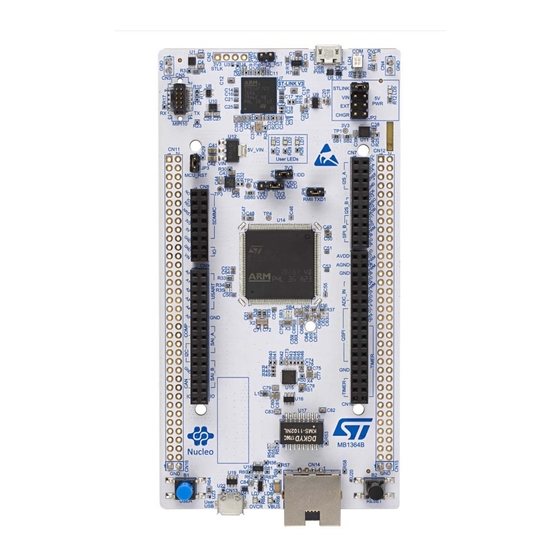
Figure 1. Nucleo-144 board (top view)
Figure 2. Nucleo-144 board (bottom view)
Pictures are not contractual.
March 2019
UM2407 Rev 1
1/48
www.st.com
1
Advertisement
Table of Contents

Related Manuals for STMicroelectronics STM32H7 Nucleo-144


Summary of Contents for STMicroelectronics STM32H7 Nucleo-144
-
Page 1: Figure 1. Nucleo-144 Board (Top View)
Zio connector, which extends the Arduino™ Uno V3 connectivity, and the ST morpho headers provide an easy means of expanding the functionality of the Nucleo open development platform with a wide choice of specialized shields. The STM32H7 Nucleo-144 boards do not require any separate probe as they integrate the STLINK-V3 debugger/programmer. -
Page 2: Table Of Contents
Contents UM2407 Contents Features ........... 6 Ordering information . - Page 3 UM2407 Contents Board functions ..........26 6.6.1 LEDs .
- Page 4 List of tables UM2407 List of tables Table 1. Ordering information ............7 Table 2.
- Page 5 UM2407 List of figures List of figures Figure 1. Nucleo-144 board (top view)..........1 Figure 2.
-
Page 6: Features
Features UM2407 Features The STM32H7 Nucleo-144 boards offer the following features: ®(a) ® • STM32H7 Arm Cortex core-based microcontroller in LQFP144 package • Ethernet compliant with IEEE-802.3-2002 (depending on STM32H7 support) • USB OTG full-speed • 3 user LEDs •... -
Page 7: Ordering Information
UM2407 Ordering information Ordering information To order the Nucleo-144 board corresponding to the targeted STM32, use the order code given below in Table Table 1. Ordering information Order code Board reference Target STM32H7 Differentiating feature – Ethernet – USB OTG FS on NUCLEO-H743ZI STM32H743ZIT6U Micro.AB connector... - Page 8 Ordering information UM2407 Table 2. Codification explanation NUCLEO-XXYYZTN Description Example: NUCLEO-H743ZI2 STM32H7 Flash memory size: 2 Mbytes -I for 2 Mbytes Board version: -void = ST-LINK/V2-1 STLINK-V3E -2 = STLINK-V3E This order code is mentioned on a sticker placed on top side of the board. 8/48 UM2407 Rev 1...
-
Page 9: Development Environment
UM2407 Development environment Development environment Development toolchains ® • Keil MDK-ARM ™ • EWARM • GCC-based IDEs System requirements ® ® ®(b) • Windows OS (7, 8 and 10), Linux or macOS • USB Type-A to Micro-B cable Demonstration software The demonstration software, included in the STM32Cube package, is preloaded in the STM32H7 Flash memory for easy demonstration of the device peripherals in standalone mode. -
Page 10: Conventions
SBx connections closed by solder or 0 ohm resistor Solder bridge SBx OFF SBx connections left open In this document, for any information that is common to all sales types, the references are noted “STM32H7 Nucleo-144 board” and “STM32H7 Nucleo-144 boards”. 10/48 UM2407 Rev 1... -
Page 11: Quick Start
Nucleo USB driver available on the www.st.com/stm32nucleo website. To power the board connect the STM32H7 Nucleo-144 board to a PC with a USB cable ‘Type-A to Micro-B’ through the USB connector CN1 on the ST-LINK. As a result, the green LED LD6 (PWR) and LD4 (COM) light up and the red LED LD3 blinks. -
Page 12: Hardware Layout And Configuration
Hardware layout and configuration UM2407 Hardware layout and configuration The STM32H7 Nucleo-144 board is designed around the STM32H7 Series microcontrollers in a 144-pin LQFP package. Figure 3 shows the connections between the STM32H7 and its peripherals (STLINK-V3, push-buttons, LEDs, USB, Ethernet, ST Zio connectors and ST morpho headers). -
Page 13: Nucleo-144 Board Layout
UM2407 Hardware layout and configuration Nucleo-144 board layout Figure 4. Nucleo-144 board top layout UM2407 Rev 1 13/48... -
Page 14: Figure 5. Nucleo-144 Bottom Layout
Hardware layout and configuration UM2407 Figure 5. Nucleo-144 bottom layout 14/48 UM2407 Rev 1... -
Page 15: Mechanical Drawing
UM2407 Hardware layout and configuration Mechanical drawing Figure 6. Nucleo-144 board mechanical drawing in millimeter UM2407 Rev 1 15/48... -
Page 16: Figure 7. Nucleo-144 Board Mechanical Drawing In Mil
Hardware layout and configuration UM2407 Figure 7. Nucleo-144 board mechanical drawing in mil 16/48 UM2407 Rev 1... -
Page 17: Embedded Stlink-V3
In case the STM32H7 Nucleo-144 board is connected to the PC before installing the driver, the PC device manager may report some Nucleo interfaces as “Unknown”. To recover from this situation, after installing the dedicated driver, the association of “Unknown”... -
Page 18: Stlink-V3 Firmware Upgrade
STLINK-V3 firmware up to date before starting to use the STM32H7 Nucleo-144 board. The latest version of this firmware is available from the www.st.com website. -
Page 19: Table 5. Mipi-10 Debug Connector (Cn5)
UM2407 Hardware layout and configuration Figure 9. Connecting an external debug tool to program the on-board STM32H7 Table 5. MIPI-10 debug connector (CN5) MIPI-10 STDC14 Designation Reserved Reserved T_VCC Target VCC Target SWDIO using SWD protocol or Target JTMS T_SWDIO (T_JTMS) using JTAG protocol Ground Target SWCLK using SWD protocol or Target JCLK (T_JCLK) -
Page 20: Power Supply
6.4.1 Power supply input from STLINK-V3 USB connector (default setting) The STM32H7 Nucleo-144 board and shield can be powered from the ST-LINK USB connector CN1 (5 V), by placing a jumper between the pins 1-2 of JP2 "STLINK" (see Figure 10). -
Page 21: External Power Supply Input From Vin (7 V To 12 V, 800 Ma Max)
Warning: In case the maximum current consumption of the STM32H7 Nucleo-144 board and its shield boards exceed 300 mA, it is mandatory to power the STM32H7 Nucleo-144 board, using an external power supply connected to E5V, V or +3.3 V. -
Page 22: External Power Supply Input 5V_Ext (5 V, 500 Ma Max)
Section 6.4.6 about debugging when using an external power supply. 6.4.3 External power supply input 5V_EXT (5 V, 500 mA max) When STM32H7 Nucleo-144 board is power supplied by EXT (see Table 7 Figure 12), the jumper configuration must be the following: Jumper JP2 on pin 5-6 "EXT"... -
Page 23: External Power Supply Input From Usb Charger (5 V)
Figure 12. Power supply input from 5V_EXT (5 V, 500 mA max) 6.4.4 External power supply input from USB CHARGER (5 V) When STM32H7 Nucleo-144 board is power supplied by a USB charger on CN1 (see Table 8 Table 13), the jumper configuration must be the following: Jumper JP2 on pin 7-8 "CHGR". -
Page 24: Debugging While Using Vin Or Ext As An External Power Supply
Hardware layout and configuration UM2407 Table 9. External power sources: 3V3_EXT (3.3 V) Input power name Connector pins Voltage range Max current CN8 pin 7 3 V to 3.6 V 1.3 A CN11 pin 16 Figure 14. Power supply input from 3V3_EXT (3.3 V) 6.4.6 Debugging while using VIN or EXT as an external power supply When powered by VIN or EXT, it is still possible to use the ST-LINK for programming or... -
Page 25: Clock Sources
UM2407 Hardware layout and configuration Clock sources 6.5.1 HSE clock (high speed external clock) There are four ways to configure the pins corresponding to the external high-speed clock (HSE): • MCO from ST-LINK (default): MCO output of ST-LINK is used as input clock. This frequency cannot be changed, it is fixed at 8 MHz and connected to the PF0/PH0- OSC_IN of STM32H7 Series microcontroller. -
Page 26: Board Functions
Hardware layout and configuration UM2407 NX3215SA-32.768kHZ-EXS00A-MU00525 (32.768 kHz, 6 pf load capacitance, 20 ppm) from NDK. The configuration must be: – SB40 and SB41 OFF – R38 and R39 ON • Oscillator from external PC14: from external oscillator through the pin 25 of CN11 connector. -
Page 27: Mcu Voltage Selection: 1V8/3V3
6.6.5 Virtual COM port (VCP): LPUART/USART The STM32H7 Nucleo-144 board offers the possibility to connect a LPUART or an USART interface to the ST-LINK or to the ST morpho connectors and Arduino™ Uno V3 connectors. The selection is done by settings the related solder bridges. (Refer to... -
Page 28: Usb Otg Fs
STM32H7 I/Os. A green LED LD8 lights in one of these cases: • Power switch (U12) is ON and STM32H7 Nucleo-144 board works as a USB host • is powered by another USB host when the STM32H7 Nucleo-144 board works as a USB device. -
Page 29: Ethernet
USB FS OVCR SB76 ON SB76 OFF ESD protection part USBLC6-2SC6 is implemented on USB port because all USB pins on STM32H7 are dedicated to USB port protection only on the STM32H7 Nucleo-144 board. USB pin ID is not used. 6.6.7 Ethernet The STM32H7 Nucleo-144 board supports 10M/100M Ethernet communication by a PHY LAN8742A-CZ-TR (U15) and RJ45 connector (CN14). -
Page 30: Table 14. Solder Bridge And Jumper Configuration
Hardware layout and configuration UM2407 Table 14. Solder bridge and jumper configuration Bridge State Description Peripheral power 3V3_PER is connected to 3V3. SB1 (3V3_PER) Peripheral power 3V3_PER is not connected. Output of voltage regulator ST1L05CPU33R is connected to 3V3. SB2 (3V3) Output of voltage regulator ST1L05CPU33R is not connected. - Page 31 UM2407 Hardware layout and configuration Table 14. Solder bridge and jumper configuration (continued) Bridge State Description ON, OFF Green user LED LD1 is connected to PB0. Green user LED LD1 is connected to D13 of Arduino signal OFF,ON SB39, SB47 (PA5).
- Page 32 Hardware layout and configuration UM2407 Table 14. Solder bridge and jumper configuration (continued) Bridge State Description PA0 is connected to ST Zio connector (Pin 29 of CN10). SB75 (PA0) PA0 is not connected to ST Zio connector (Pin 29 of CN10). RMII Signals These pins are used as RMII signals and connected to Ethernet PHY.
- Page 33 SB5 can be ON. 1. Default SBx state is shown in bold. All the other solder bridges present on the STM32H7 Nucleo-144 board are used to configure several I/Os and power supply pins for compatibility of features and pinout with the target STM32H7 supported.
-
Page 34: Board Connectors
Board connectors UM2407 Board connectors Several connectors are implemented on the STM32H7 Nucleo-144 board. STLINK-V3 USB Micro-B connector CN1 The USB Micro-B connector CN1 is used to connect embedded STLINK-V3 to the PC for the programming and debugging purposes. Figure 15. USB Micro-B connector CN1 (front view) -
Page 35: Usb Otg Fs Connector Cn13
USB_FS_ID PA10 Ethernet RJ45 connector CN14 The STM32H7 Nucleo-144 board supports 10Mbps/100Mbps Ethernet communication with the U15 LAN8742A-CZ-TR PHY from MICROCHIP and CN14 integrated RJ45 connector. The Ethernet PHY is connected to the MCU via the RMII interface. The 25 MHz clock for the PHY is generated by oscillator X4. The 50 MHz clock for the MCU (derived from the 25 MHz crystal oscillator) is provided by the RMII_REF_CLK of the PHY. -
Page 36: Table 17. Ethernet Connector Pinout
Board connectors UM2407 Figure 17. Ethernet RJ45 connector CN14 (front view) 1. Green LED: Ethernet traffic 2. Amber LED: Ethernet connection The related pinout for the Ethernet connector is listed in Table Table 17. Ethernet connector pinout Connector Description MCU pin Description MCU pin number... -
Page 37: Extension Connectors
Extension connectors Extension connectors ST Zio connectors For each STM32H7 Nucleo-144 board, the following figures show the signals connected by default to the ST Zio connectors (CN7, CN8, CN9, CN10), including the support for Arduino Uno V3. Figure 18. NUCLEO-H743ZI2 and NUCLEO-H753ZI CN7, CN8, CN9 and CN10 are female on top side and male on bottom side connectors. - Page 38 Extension connectors UM2407 Caution:1 The I/Os of STM32H7 Series microcontroller are 3.3 V compatible instead of 5 V for Arduino Uno V3. Caution:2 R37 should be removed before implementing Arduino shield with V power being REF+ provided on CN7 pin 6. Refer to Table 14: Solder bridge and jumper configuration for details on R37.
-
Page 39: Table 18. Cn7 Zio Included Arduino™ Connector Pinout
NUCLEO-H743ZI2, NUCLEO-H753ZI pin assignments Table 18. CN7 ZIO included Arduino™ connector pinout STM32H7 Signal name Pin name Signal name STM32H7 pin MCU Function name Function I2S_A_MCK I2S_2 I2C_A_SCL I2C_1_SCL I2S_A_SD PB15 I2S_2 I2C_A_SDA I2C_1_SDA I2S_A_CK PB13 I2S_2 VREFP VREFP VDDA/VREFP I2S_A_WS PB12 I2S_2... -
Page 40: Table 20. Cn9 Zio Included Arduino™ Connector Pinout
Table 19. CN8 ZIO included Arduino™ connector pinout (continued) STM32H7 STM32H7 Pin name Signal name MCU Function Pin name Signal name MCU Function 3.3 V input/output SDMMC_D3 PC11 SDMMC 5 V output SDMMC_CK PC12 SDMMC ground SDMMC_CMD SDMMC ground Power input Table 20. -
Page 41: Table 21. Cn10 Zio Included Arduino™ Connector Pinout
Table 20. CN9 ZIO included Arduino™ connector pinout (continued) STM32H7 STM32H7 Pin name Signal name MCU Function Pin name Signal name MCU Function CAN_TX CAN_1 SAI_B_FS SAI_1_B 1. PE2 is connected to both CN9 pin 14 (SAI_A_MCLK) and CN10 pin 25 (QSPI_BK1_IO2). Only one function must be used at one time. Table 21. -
Page 42: St Morpho Connector
The ST morpho connector consists in male pin header footprints CN11 and CN12 (not soldered by default). They are used to connect the STM32H7 Nucleo-144 board to an extension board or a prototype/wrapping board placed on top of the STM32H7 Nucleo-144 board. - Page 43 UM2407 Extension connectors Table 22. ST morpho connector pin assignment (continued) CN11 odd pins CN11 even pins CN12 odd pins CN12 even pins Pin nbr Pin name Pin nbr Pin name Pin nbr Pin name Pin nbr Pin name PE15 PE13 PE11 PF13...
-
Page 44: Appendix A Federal Communications Commission (Fcc)
A.1.3 Part 15.21 Any changes or modifications to this equipment not expressly approved by STMicroelectronics may cause harmful interference and void the user's authority to operate this equipment. IC Compliance Statement This device complies with FCC and Industry Canada RF radiation exposure limits set forth for general population for mobile application (uncontrolled exposure). - Page 45 UM2407 Federal Communications Commission (FCC) and Industry Canada (IC) Compliance accepter tout brouillage radioélectrique subi, même si le brouillage est susceptible d'en compromettre le fonctionnement Étiquette de conformité à la NMB-003 d'Industrie Canada: CAN ICES-3 (A)/NMB-3(A) UM2407 Rev 1 45/48...
-
Page 46: Appendix Bcispr32
CISPR32 UM2407 Appendix B CISPR32 Warning Warning: This device is compliant with Class A of CISPR32. In a residential environment, this equipment may cause radio interference. Avertissement: Cet équipement est conforme à la Classe A de la CISPR 32. Dans un environnement résidentiel, cet équipement peut créer des interférences radio. -
Page 47: Revision History
UM2407 Revision history Revision history Table 23. Document revision history Date Revision Changes 14-Mar-2019 Initial version UM2407 Rev 1 47/48... - Page 48 IMPORTANT NOTICE – PLEASE READ CAREFULLY STMicroelectronics NV and its subsidiaries (“ST”) reserve the right to make changes, corrections, enhancements, modifications, and improvements to ST products and/or to this document at any time without notice. Purchasers should obtain the latest relevant information on ST products before placing orders.
Need help?
Do you have a question about the STM32H7 Nucleo-144 and is the answer not in the manual?
Questions and answers