Table of Contents
Advertisement
Quick Links
Introduction
The L62xx family evaluation environment is a fast, robust, and easy-to-use solution that allows to evaluate all the brush DC
and stepper motor drivers of the L62xx family in combination with a NUCLEO-F401RE control board and the STSPIN Studio
software.
The kit includes:
•
a compact main board (EVL62XX-MAIN) compatible with the Arduino UNO R3 connector
•
one plug-in board (EVL62XX-PLUG) based on the DMOS dual full-bridge driver for motor control of the STMicroelectronics
L62xx family. In particular:
L6205, L6225, L6206, L6226, L6207 and L6227 to drive from one to four DC motors
L6208 and L6228 DMOS to drive one bipolar stepper motor.
The maximum ratings of the plug-in boards are:
•
power stage supply voltage (VS) from 8 V to 50 V
•
motor phase current up to 1.4 A r.m.s. (L6225, L6226, L6227 and L6228)
•
motor phase current up to 2.8 A r.m.s. (L6205, L6206, L6207 and L6208)
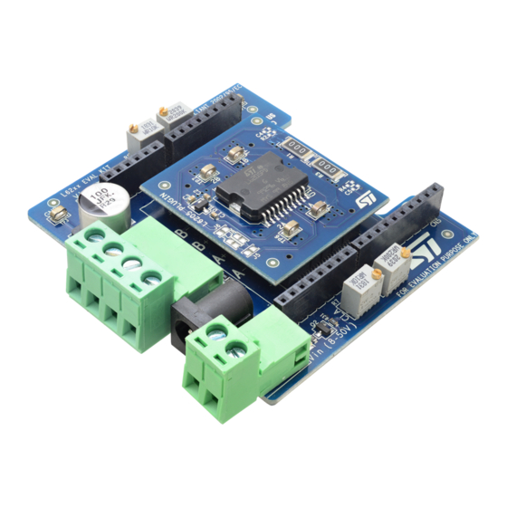
Figure 1.
UM2871 - Rev 1 - July 2021
For further information contact your local STMicroelectronics sales office.
Dual brush DC motor and stepper motor evaluation kit
L62XX evaluation environment mounting L6205 driver board
UM2871
User manual
www.st.com
Advertisement
Table of Contents

Subscribe to Our Youtube Channel
Related Manuals for STMicroelectronics L62 Series


Summary of Contents for STMicroelectronics L62 Series
-
Page 1: Figure 1. L62Xx Evaluation Environment Mounting L6205 Driver Board
(EVL62XX-MAIN) compatible with the Arduino UNO R3 connector • one plug-in board (EVL62XX-PLUG) based on the DMOS dual full-bridge driver for motor control of the STMicroelectronics L62xx family. In particular: L6205, L6225, L6206, L6226, L6207 and L6227 to drive from one to four DC motors L6208 and L6228 DMOS to drive one bipolar stepper motor. -
Page 2: Getting Started
UM2871 Getting started Getting started The EVL62XX evaluation environment covers a wide range of applications and it is ready to be used in a few steps. Follow this procedure to start your evaluation: Check the setting of the jumpers based on your configuration as described in Section 2: "Hardware description and configuration". -
Page 3: Hardware Description And Configuration
UM2871 Hardware description and configuration Hardware description and configuration Figure 2. EVL62XX-MAIN main board overview OCD threshold trimmer (Bridge B) Arduino Uno R3 connector TOFF trimmer (Bridge B) Arduino Uno R3 connector Plug-in board with selected device Motor phases connector Arduino Uno R3 connector CN2, CN3 TOFF trimmer (Bridge A) -
Page 4: Overcurrent (Ocd) Threshold Setting (L6206 And L6226)
UM2871 Overcurrent (OCD) threshold setting (L6206 and L6226) Table 2. Arduino UNO R3 connector table (L62x8 devices) Connector Signal Remarks Reset Fault Enable ADC-6 Ground HALF/FULL CONTROL VREFA CLOCK CW/CCW ADC-4 VREFB Ground Ground 1. All non-listed pins are not connected. Overcurrent (OCD) threshold setting (L6206 and L6226) The plug-in boards based on L6206 and L6226 devices integrate two overcurrent protection circuits with adjustable threshold, one for each full-bridge. -
Page 5: Toff Setting (L6207, L6208, L227 And L6228)
UM2871 TOFF setting (L6207, L6208, L227 and L6228) Figure 4. L6226: Overcurrent threshold vs. resistor value (no paralleling) SOVER [Ω] When one of the paralleling modes is used, the actual OCD threshold value is scaled as indicated in Table Further details are available in the application note AN1762, “L6205, L6206, L6207 DUAL FULL-BRIDGE DRIVERS”, on the st.com website. -
Page 6: Table 3. Hardware Configurations
UM2871 Driving mode selection (L6205, L6225, L6206 and L6226) The driving mode selection is done by properly setting J5, J6, J7 and J8 solder jumpers on the top of the boards. By default, all solder jumpers are open (two bidirectional DC motor driving configuration). The table below briefly summarizes the possible configurations: Table 3. -
Page 7: Figure 6. Two Bidirectional Dc Motors
UM2871 Driving mode selection (L6205, L6225, L6206 and L6226) Figure 6. Two bidirectional DC motors Figure 7. Four unidirectional DC motors UM2871 - Rev 1 page 7/26... -
Page 8: Figure 8. One Bidirectional Dc Motor - Higher Current
UM2871 Driving mode selection (L6205, L6225, L6206 and L6226) Figure 8. One bidirectional DC motor – higher current Figure 9. Two unidirectional DC motors – higher current UM2871 - Rev 1 page 8/26... -
Page 9: Figure 10. One Bidirectional Dc Motor - Lower Overcurrent
UM2871 Driving mode selection (L6205, L6225, L6206 and L6226) Figure 10. One bidirectional DC motor – lower overcurrent Figure 11. Two unidirectional DC motors – lower overcurrent UM2871 - Rev 1 page 9/26... -
Page 10: Figure 12. One Unidirectional Dc Motor - All Bridges Parallel
UM2871 Driving mode selection (L6205, L6225, L6206 and L6226) Figure 12. One unidirectional DC motor – all bridges parallel UM2871 - Rev 1 page 10/26... -
Page 11: Safety Precautions
UM2871 Safety precautions Safety precautions Warning: Some of the components mounted on the board could reach hazardous temperature during operation. While using the board, please follow the precautions below: • Do not touch the components or the heatsink. • Do not cover the board. •... -
Page 12: Bills Of Material
UM2871 Bills of material Bills of material Table 4. EVL62XX-MAIN bill of material Item Q.ty Ref. Description Part/Value Manufact. Order code Wurth 691312510004 or Connector 5.08 mm close vertical CON-1x4 Elektronik equivalent Jack connector, 2,1 mm, 2,5 mm, Jack connector RS 805-1699 or equivalent female, PCB mounting Wurth... -
Page 13: Table 5. Evl6205-Plug Bill Of Materials
Part/Value Manufact. Order code SMT ceramic capacitor 10nF/50V SMT ceramic capacitor 100nF/50V SMT ceramic capacitor 220nF/35V C4,C5 SMT ceramic capacitor N.M. High speed double BAR43 STMicroelectronics BAR43SFILM switching diode BTE-020-01-F-D-A-TR or J1,J2 Terminal strip BTE-020-01-F-D-A-TR Samtec equivalent R1,R3 SMT resistor... -
Page 14: Table 7. Evl6207-Plug Bill Of Materials
Order code SMT resistor 100R TP4,TP5, S1751-46R or SMT test point TESTPOINT Harwin equivalent TP6,TP7 DMOS dual full-bridge L6206PD STMicroelectronics L6206PD driver Table 7. EVL6207-PLUG bill of materials Item Q.ty Ref. Description Part/Value Manufact. Order code SMT ceramic capacitor 10nF/50V... -
Page 15: Table 9. Evl6225-Plug Bill Of Materials
Order code SMT ceramic capacitor 10nF/50V SMT ceramic capacitor 100nF/50V SMT ceramic capacitor 220nF/35V C4,C5 SMT ceramic capacitor N.M. High speed double BAR43 STMicroelectronics BAR43SFILM switching diode BTE-020-01-F-D-A-TR J1,J2 Terminal strip BTE-020-01-F-D-A-TR Samtec or equivalent R1,R3 SMT resistor R2,R4 SMT resistor N.M. -
Page 16: Table 11. Evl6227-Plug Bill Of Materials
R14,R15, R16,R17, R5,R6, R10,R13, SMT resistor TP4,TP5, SMT test point TESTPOINT Harwin S1751-46R or equivalent TP6,TP7 DMOS dual full-bridge L6226PD STMicroelectronics L6226PD driver Table 11. EVL6227-PLUG bill of materials Q.ty Ref. Description Part/Value Manufact. Order code SMT ceramic capacitor 10nF/50V... -
Page 17: Table 12. Evl6228-Plug Bill Of Materials
UM2871 Bills of material Q.ty Ref. Description Part/Value Manufact. Order code DMOS dual full-bridge L6227PD STMicroelectronics L6227PD driver Table 12. EVL6228-PLUG bill of materials Q.ty Ref. Description PartValue Manufact. Order code SMT ceramic capacitor 10nF/50V C2,C6 SMT ceramic capacitor 100nF/50V... -
Page 18: Schematic Diagrams And Layouts
UM2871 Schematic diagrams and layouts Schematic diagrams and layouts Figure 13. EVL62XX-MAIN schematic diagram FID1 FID40RD_80RD FID2 FID40RD_80RD FID3 NUCLEO & LOGO FDV302P FDV302P FID40RD_80RD FAULTA FOR EVALUATION PURPOSE ONLY FAULTB ROHS COMPLIANT 2002/95/IEC & LOGO Gre e n 330R 330R TP 1 Re d... -
Page 19: Figure 15. Evl6206-Plug Schematic Diagram
UM2871 Schematic diagrams and layouts Figure 15. EVL6206-PLUG schematic diagram OUT2A OUT2A 220NF BAR43 ENA_RS T ENA_RS T VREFA_P CA VREFA_P CA FID1 IN1A_CLOCK IN2A_C/CCW FID40RD_80RD OCDA_RCA S ENS EA FID2 10NF OUT1A OUT1A FID40RD_80RD 100R FID3 FID40RD_80RD BTE-020-01-F-D-A-TR ENA_RS T ENB_ENABLE 100NF IN1A_CLOCK... -
Page 20: Figure 18. Evl6225-Plug Schematic Diagram
UM2871 Schematic diagrams and layouts Figure 18. EVL6225-PLUG schematic diagram C3 220NF BAR43 OUT2A OUT2A 10NF IN1A IN2A S ENS EA OUT1A OUT1A 100NF IN1A L6225P D TP 4 IN2A OUT1A TP 5 OUT1A BTE-020-01-F-D-A-TR OUT1B OUT1B OUT2A OUT2A IN1A OUT2B TP 6 IN2A... -
Page 21: Figure 20. Evl6227-Plug Schematic Diagram
UM2871 Schematic diagrams and layouts Figure 20. EVL6227-PLUG schematic diagram OUT2A OUT2A 220NF BAR43 ENA_RS T ENA_RS T VREFA_P CA VREFA_P CA IN1A_CLOCK IN2A_C/CCW OCDA_RCA S ENS EA 10NF FID1 OUT1A OUT1A FID40RD_80RD FID2 BTE-020-01-F-D-A-TR ENA_RS T FID40RD_80RD ENB_ENABLE 100NF FID3 IN1A_CLOCK IN2A_C/CCW... -
Page 22: Revision History
UM2871 Revision history Table 13. Document revision history Date Version Changes 08-Jul-2021 Initial release. UM2871 - Rev 1 page 22/26... -
Page 23: Table Of Contents
UM2871 Contents Contents Getting started ..............2 Hardware description and configuration . -
Page 24: List Of Tables
UM2871 List of tables List of tables Table 1. Arduino UNO R3 connector table (L62x5, L62x6 and L62x7 devices) ....... . 3 Table 2. -
Page 25: List Of Figures
UM2871 List of figures List of figures Figure 1. L62XX evaluation environment mounting L6205 driver board ........1 Figure 2. - Page 26 IMPORTANT NOTICE – PLEASE READ CAREFULLY STMicroelectronics NV and its subsidiaries (“ST”) reserve the right to make changes, corrections, enhancements, modifications, and improvements to ST products and/or to this document at any time without notice. Purchasers should obtain the latest relevant information on ST products before placing orders. ST products are sold pursuant to ST’s terms and conditions of sale in place at the time of order acknowledgement.
Need help?
Do you have a question about the L62 Series and is the answer not in the manual?
Questions and answers