Table of Contents
Advertisement
Quick Links
UM2027
User manual
Inrush current limitation when charging a DC bus capacitor for
IEC 61000-3-3 compliance
Introduction
The STEVAL-IHT008V1 evaluation board limits the inrush current charging a DC bus capacitor so that it
is compliant with the IEC 61000-3-3 standard. This inrush current is based on a soft-start procedure for
the rectifier bridge achieved with a Triac added in series with the mains line, which is controlled through
progressive phase-control during the startup phase.
This solution drastically reduces standby losses as the DC bus can be totally disconnected from the AC
mains when it is not required. The DC bus is easily turned off by turning off the series Triac, without
needing an additional relay to open the circuit in standby.
Steady-state losses are also reduced because NTC resistors, traditionally used to limit inrush current,
are not required; nor are the corresponding relays to bypass them.
This board also demonstrates that AC loads can be driven with an isolated easy-to-design solution by
using the same power supply as the whole system and some opto-transistors which control the AC
switches.
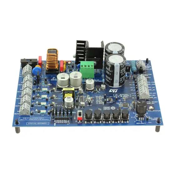
Figure 1: STEVAL-IHT008V1 evaluation board (top view)
March 2016
DocID029048 Rev 1
1/37
www.st.com
Advertisement
Table of Contents

Subscribe to Our Youtube Channel
Related Manuals for STMicroelectronics STEVAL-IHT008V1


Summary of Contents for STMicroelectronics STEVAL-IHT008V1
-
Page 1: User Manual
IEC 61000-3-3 compliance Introduction The STEVAL-IHT008V1 evaluation board limits the inrush current charging a DC bus capacitor so that it is compliant with the IEC 61000-3-3 standard. This inrush current is based on a soft-start procedure for the rectifier bridge achieved with a Triac added in series with the mains line, which is controlled through progressive phase-control during the startup phase. -
Page 2: Table Of Contents
Control with an external microcontroller .......... 12 Conclusion ..................13 STEVAL-IHT008V1 circuit schematics ........14 STEVAL-IHT008V1 power supplies and typical consumption ... 17 Inrush-current limitation .............. 19 Mains voltage dips and interruptions ......... 23 AC voltage monitoring and zero-voltage synchronisation ..26 Triacs and AC switches insulated control ........ -
Page 3: Evaluation Board Objectives
The STEVAL-IHT008V1 board is designed to demonstrate these criteria independently; you only need to connect the AC loads to check this part. The STEVAL-IHT008V1 board is also intended as a development tool for designers who want to design a whole system (appliance, air conditioning system, telecom power supply, etc.). -
Page 4: Targeted Applications
Evaluation board objectives UM2027 Figure 2: Board synopsis Targeted applications Target applications include all applications using a diode-bridge to rectify the line AC voltage and require the removal of the NTC (or PTC) resistor and the limitation of standby losses. Such applications include: ... -
Page 5: Operating Range And Performances
Evaluation board objectives T4 and T5: Z0109MUF (SMD package) Operating range and performances The STEVAL-IHT008V1 board is designed to operate inside the following operating ranges: Line voltage, 2 ranges are possible: 198-264 V RMS, 50 or 60 Hz ... - Page 6 Section 7: "Mains voltage dips and interruptions"). Figure 4: "Inrush current at STEVAL-IHT008V1 startup on 230 V line (500 µF output DC capacitor)" shows an example of the progressive DC capacitor charge ensured by the T_ICL Triac. The test is performed at startup when the STEVAL-IHT008V1 board is connected to a 230 V 50 Hz grid, while the output DC capacitor is completely uncharged (initial voltage is zero).
-
Page 7: Stand-By Consumption
UM2027 Evaluation board objectives Figure 4: Inrush current at STEVAL-IHT008V1 startup on 230 V line (500 µF output DC capacitor) Stand-by consumption One of the main advantages of using the T_ICL Triac in front of the rectifier bridge is that it allows full bridge disconnection during standby to suppress losses. - Page 8 Evaluation board objectives UM2027 one bypass relay (refer to RLIM and S1 on Figure 5: "Solution using relays to limit inrush current and standby losses"). Case 3: as above, but circuits used solely for demonstration purposes and which consume undesired power at standby are disconnected. These circuits are the "HV Capacitor Discharge"...
-
Page 9: Getting Started
Getting started Safety instruction The high voltage levels used to operate the STEVAL-IHT008V1 evaluation board can represent a serious electrical shock hazard. This evaluation board must be used in a suitable laboratory only by qualified personnel who are familiar with the installation, use, and maintenance of power electrical systems. -
Page 10: Dc Bus Capacitor Discharge For Demonstration Purpose
(rectifier mode) DC bus capacitor discharge for demonstration purpose With default STEVAL-IHT008V1 1000 µF output capacitors (C1, C5) and associated 50 kΩ resistors (R9, R11, R14, R16) used in parallel to balance the voltage across the two series capacitor, the DC bus discharging time takes a few minutes if no load is connected. -
Page 11: Possible Board Adaptations
"OUT1" to "OUT5" (LED6 to LED10) are ON when the corresponding AC switch (T1 to T5) is turned on. Possible board adaptations The STEVAL-IHT008V1 board allows certain external components to be added to the front- end circuit, so designers can validate an entire system. The main possible modifications are listed below. -
Page 12: Power Factor Circuit Connection
PFC can be used. For correct operation of the STEVAL-IHT008V1 front-end circuit with a PFC, the PFC must be activated after the "PFC_START" signal has been set to a 5 V high level. This signal is referenced to the GND_DC terminal. -
Page 13: Conclusion
This evaluation provides an innovative front-end circuit to allow both inrush current limitation and power loss reduction. Above and beyond the simple demonstration of the efficiency and the robustness of this solution by STMicroelectronics, this front-end circuit also represents the starting point for building entire system and accelerating the time-to- market of new application designs. -
Page 14: Steval-Iht008V1 Circuit Schematics
STEVAL-IHT008V1 circuit schematics UM2027 STEVAL-IHT008V1 circuit schematics Figure 8: STEVAL-IHT008V1 power side and insulated control schematic 14/37 DocID029048 Rev 1... - Page 15 UM2027 STEVAL-IHT008V1 circuit schematics Figure 9: STEVAL-IHT008V1 control circuit schematic (1 of 3) DocID029048 Rev 1 15/37...
- Page 16 STEVAL-IHT008V1 circuit schematics UM2027 Figure 10: STEVAL-IHT008V1 control circuit schematic (2 of 3) Figure 11: STEVAL-IHT008V1 control circuit schematic (3 of 3) 16/37 DocID029048 Rev 1...
-
Page 17: Steval-Iht008V1 Power Supplies And Typical Consumption
These measurements are performed with the STEVAL-IHT008V1 connected to either a 230 V or 120 V line, with the bridge operating in rectifier mode (not doubler) and across the entire operating temperature range (0-60 °C). - Page 18 STEVAL-IHT008V1 power supplies and typical UM2027 consumption Figure 14: "Inrush current during STEVAL-IHT008V1 startup on 230 V line (500 µF output DC capacitor)", the output current of the horizontal axis gives the extra current sunk from the output voltage when one ACS switch is ON. This means that for a zero current, a current close to 20 mA is already sunk from the VCC_AC supply.
-
Page 19: Inrush-Current Limitation
29.3 16.1 34.1 STEVAL-IHT008V1 compliance with the IEC 61000-3-3 limit Currently, one of the most used solutions to limit inrush current consists of adding a resistor (refer to RLIM in Figure 5: "Solution using relays to limit inrush current and standby losses") - Page 20 The minimum value of 3 ms is defined by the Phase_Control_ON_Max which sets the maximum T_ICL ON time (7 ms, refer to directive definitions in the firmware). Figure 14: "Inrush current during STEVAL-IHT008V1 startup on 230 V line (500 µF output DC capacitor)" (same as Figure 4: "Inrush current at STEVAL-IHT008V1 startup on 230 V...
- Page 21 UM2027 Inrush-current limitation Figure 14: Inrush current during STEVAL-IHT008V1 startup on 230 V line (500 µF output DC capacitor) Here, the MCU firmware is the default program, so: the first T_ICL turn-on is set to 410 µs before next line Zero Voltage. As the first gate current pulse lasts 50 µs, the gate current can be removed 360 µs before the next half...
- Page 22 Inrush-current limitation UM2027 time of deviation exceeding 3.3%. Here, the output capacitor is charged in 550 ms and compliance with IEC 61000-3-3 is achieved. It should also be noted that the peak current during output capacitor charge is not constant. Indeed, only the step of the reduction of the T_ICL Triac turn-on delay is constant.
-
Page 23: Mains Voltage Dips And Interruptions
A criteria B is requested for the 0% voltage test during 1 cycle, while the other tests require only a criteria C. The MCU firmware of the STEVAL-IHT008V1 board is programmed in order to comply with these different standard tests with the following strategy: ... - Page 24 The test results of the STEVAL-IHT008V1 board are also given for all tests. These tests results only apply to the inrush current limitation function (thus T_ICL Triac control).
- Page 25 UM2027 Mains voltage dips and interruptions Required STEVAL- Number Standard Application Test type residual criteria by IHT008V1 of cycles voltage standard result 61000-2-1 environments Interruptions /300 < 5 Information EN55024 technology equipment < 5 appliances, EN55014- electric tools, etc. DocID029048 Rev 1 25/37...
-
Page 26: Ac Voltage Monitoring And Zero-Voltage Synchronisation
AC voltage monitoring and zero-voltage UM2027 synchronisation AC voltage monitoring and zero-voltage synchronisation Zero-Voltage and AC line voltage sensor circuits The AC line voltage (V ) must be measured to detect the AC line voltage level and to manage the AC line dips (as described in Section 7: "Mains voltage dips and interruptions"). - Page 27 UM2027 AC voltage monitoring and zero-voltage synchronisation The next equation gives the proportional coefficient between V and V AC_IM = 2 MΩ, V For example, with R = 264 V, and V = 4 V, the following AC_RMS_Max AC_IM_Max resistor values and the K parameter are determined. For high accuracy, a 1% resistor tolerance is recommended.
- Page 28 AC voltage monitoring and zero-voltage UM2027 synchronisation Figure 19: Zero AC line voltage crossing detection 28/37 DocID029048 Rev 1...
-
Page 29: Triacs And Ac Switches Insulated Control
AC switch gates. All the AC switches on the STEVAL-IHT008V1 boards are so controlled in quadrants 2 and 3. For more information regarding this, refer to AN3168 or AN4564. - Page 30 Triacs and AC switches insulated control UM2027 the NPN transistor collector-emitter, I the TRIAC gate current and V is the TRIAC gate triggering voltage. The collector resistor (R ) of the NPN transistor is defined in the next equation, with R40 being the NPN transistor resistor filter, VCC_AC the power supply to provide the gate current to the AC switch, VCE(SAT) the transistor collector-emitter of the optocoupler,...
-
Page 31: En55014 Test Results
UM2027 EN55014 test results EN55014 test results Figure 21: EMI noise test with 1000 W load Figure 22: EMI noise test without load DocID029048 Rev 1 31/37... -
Page 32: Steval-Iht008V1 Silk-Screen
STEVAL-IHT008V1 silk-screen UM2027 STEVAL-IHT008V1 silk-screen Figure 23: STEVAL-IHT008V1 silk-screen (Top side) Table 5: Bill of material Reference Part / Value C1, C9 1000 µF / 250 V C2, C4, C5, C8 2.2 nF / 440 VAC C6, C7 56 nF / 300 V... - Page 33 UM2027 STEVAL-IHT008V1 silk-screen Reference Part / Value 22 µF / 450 V 2.2 µF / 63 V 680 pF / 50 V 100 nF / 50 V 330 n / 50 V BZX55C30 D2, D6, D7, D8, D9, D10 BZX55C5V6...
- Page 34 STEVAL-IHT008V1 silk-screen UM2027 Reference Part / Value R32, R33 300 R / 0.125 W 21.5 k / 0.25 W R37, R49 16.2 k / 0.25 W R38, R39 2.7 M / 0.25 W 4.7 k / 0.125 W R41, R43...
-
Page 35: Test Points
UM2027 Test points Test points The different test points available on the STEVAL-IHT008V1 are given in the table below. Table 6: Test points Reference Designation Definition Line after EMI filter TP2, TP21, VCC_AC TP33 HVDC Line before EMI filter OUT_ICL... -
Page 36: Revision History
Revision history UM2027 Revision history Table 7: Document revision history Date Revision Changes 09-Mar-2016 Initial release. 36/37 DocID029048 Rev 1... - Page 37 IMPORTANT NOTICE – PLEASE READ CAREFULLY STMicroelectronics NV and its subsidiaries (“ST”) reserve the right to make changes, corrections, enhancements, modifications, and improvements to ST products and/or to this document at any time without notice. Purchasers should obtain the latest relevant information on ST products before placing orders.
Need help?
Do you have a question about the STEVAL-IHT008V1 and is the answer not in the manual?
Questions and answers