
Related Manuals for Renishaw OTS


Summary of Contents for Renishaw OTS
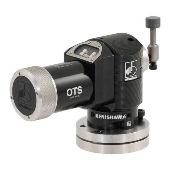
- Page 1 Installation guide H-5514-8504-02-B OTS optical tool setter www.armata-cnc.ru info@armata-cnc.ru +7(495)797-78-97...
- Page 2 © 2008 - 2009 Renishaw plc. All rights reserved. This document may not be copied or reproduced in whole or in part, or transferred to any other media or language, by any means, without the prior written permission of Renishaw plc.
-
Page 3: Table Of Contents
2.0 OTS basics Introduction .....................2.1 Operation ....................2.2 Modes of operation .................2.3 Configurable settings ................2.4 OTS dimensions ..................2.5 OTS specification ...................2.6 Principal application ................2.6 Overall dimensions ................2.6 Weight ....................2.6 Operating ..................2.6 Batteries . - Page 4 Preparing the OTS for use ..............3.3 Fitting the stylus, break stem and captive link ........3.3 Installing the batteries ...............3.4 Mounting the OTS on a machine table ..........3.5 Positioning the optical module ............3.6 Stylus level setting ................3.7 Square stylus only .
-
Page 5: Before You Begin
INACCURACIES IN THIS DOCUMENT. manufacturer's instructions. Trademarks Care of the probe RENISHAW® and the probe emblem used in the Keep system components clean and treat the RENISHAW logo are registered trademarks of probe as a precision tool. Renishaw plc in the UK and other countries. -
Page 6: Patents
OTS installation guide Patents Features of the OTS probe, and other similar Renishaw probes, are the subject of one or more of the following patents and/or patent applications: 0695926 2994401 0974208 2004-522961 1130557 2004-530234 1373995 2005-502035 1397637 1425550 5150529 1503524 B... -
Page 7: Ec Declaration Of Conformity
FCC DECLARATION (USA) FCC Section 15.19 EC DECLARATION OF CONFORMITY This device complies with Part 15 of the FCC rules. Renishaw plc declares that the product:- Operation is subject to the following two conditions: Name Description Optical tool setter 1. This device may not cause harmful interference. -
Page 8: Safety
The OTS has a glass window, handle with care if to function in accordance with these regulations: broken, to avoid injury. -
Page 9: Ots Basics
OTS basics Introduction The OTS can be user configured to use one of three coded start commands, named Probe 1, The OTS is a tool setter probe with optical signal Probe 2 and Probe 3. transmission, suitable for use on small to large machining centres. -
Page 10: Operation
Recommended rotating tool feed rates Cutters should be rotated in reverse to the cutting direction. Renishaw tool setting software calculates the spindle speed and axis feed rates Rotate tool in reverse direction automatically using the following information. -
Page 11: Modes Of Operation
Modes of operation The OTS can be in one of three modes. Stand-by mode: where the OTS is waiting for a switch-on signal. Operational mode: The OTS is ready for use in the operational mode, it is activated using the switch-on method described on page 2.4. -
Page 12: Configurable Settings
The OTS is factory set to Probe 2 so that it can be used in a system with modulated spindle The OTS is factory set to Enhanced trigger filter probes. -
Page 13: Ots Dimensions
6.13 (0.24) Ø x 13 (0.51) deep MIN 5.95 (0.23) equi-spaced on Ø54 (2.125) PCD at 45° to OTS axis Square stylus Disc stylus 19.05 mm x 19.05 mm (0.75 in x 0.75 in) Ø12.7 mm × 8 mm (Ø0.5 in × 0.31 in) -
Page 14: Ots Specification
OTS installation guide OTS specification Principal application: Tool setting on CNC machining centres Overall dimensions: ½ AA battery type: Length with square stylus 122.00 mm (4.08 in) AA battery type: Length with square stylus 143.55 mm (5.65 in) All battery types: Width 60.00 mm (2.36 in) -
Page 15: Batteries
OTS specification Batteries: Battery type (½ AA LTC - standard: Lithium Thionyl Chloride (3.6 V) x 2 Battery type (AA alkaline - standard): Alkaline (1.5 V) x 2 Battery type (AA LTC - optional): Lithium Thionyl Chloride (3.6 V) x 2... - Page 16 OTS installation guide This page left intentionally blank www.armata-cnc.ru info@armata-cnc.ru +7(495)797-78-97...
-
Page 17: System Installation
Alternative orientations The spindle mounted inspection probe must use modulated transmission Probe and optical receiver Coolant residue accumulating on the OTS or The OTS probe and receiver diodes must OMI-2T/OMI-2H/OMI-2 windows may reduce be in the other's field of view and within the the signal transmission range. -
Page 18: Ots Performance Envelope With An Omi-2T/Omi-2/Omi-2H
OTS installation guide OTS performance envelope with an OMI-2T/OMI-2/OMI-2H (modulated transmission) NOTE: A single OTS configured to Probe 1 MI-2T/OMI-2/OMI-2H 75° can be used with an OMI-2 1 (3.3) 60° 2 (6.5) 45° 3 (9.8) 30° 4 (13.1) 5 (16.4) 15°... -
Page 19: Preparing The Ots For Use
Preparing the OTS for use Fitting the stylus, break stem and captive link Stylus weak link break stem 5 mm AF (thin) A stylus weak link break stem is 2.6 Nm incorporated in the stylus mounting, (1.92 lb.ft) Captive link... -
Page 20: Installing The Batteries
OTS installation guide Installing the batteries NOTES: Select suitable battery type, see page 5.3. If dead batteries are inadvertently inserted into the probe, the LEDs will remain a constant red, see page 4.4. Do not allow coolant or debris to enter the battery compartment. -
Page 21: Mounting The Ots On A Machine Table
(supplied by user) 1.1 Nm (0.81 lbf.ft) Base 1. Select a position for the OTS on the machine 4. Refit the body onto the base and tighten table. Position to minimise the possibility of screws . If a square stylus is fitted... -
Page 22: Positioning The Optical Module
OTS installation guide Positioning the optical module 0° 15° 15° 30° 30° 45° 45° Reference feature Body Optical module Clamp screw 4 mm AF 5.1 Nm (3.76 lbf.ft) 2. Rotate the optical module to line up a The optical module can be set in one of seven positions at 15°... -
Page 23: Stylus Level Setting
Stylus level setting The top surface of disc and square styli must be set level, front to back and side to side. Side to side level adjustment 2.5 mm AF 1.1 Nm (0.81 lbf.ft) Probe module Side to side level adjustment is obtained by alternately adjusting grubscrews, which causes the probe module to rotate and change the stylus level setting. - Page 24 OTS installation guide Stylus level setting Front to back level adjustment Adjusting/locking screw Height adjusting screw 4 mm AF 4 mm AF 5.1 Nm (3.76 lbf.ft) To raise front To lower front Slacken adjusting/locking screw 2 and adjust Keep slackening height adjusting screw 1 and height adjusting screw 1 until the stylus is level.
-
Page 25: Square Stylus Only
Square stylus only Square stylus rotational adjustment allows the stylus to be aligned with the machine axes. Coarse rotational adjustment Support bar Stylus break stem with captive link 2 mm AF 1.1 Nm (0.81 lbf.ft) Slacken grubscrew 1 and rotate the stylus by hand to obtain alignment, then fully tighten the grubscrew. - Page 26 OTS installation guide Square stylus only Fine rotational adjustment 3.10 Slacken the four body locking screws 1. www.armata-cnc.ru info@armata-cnc.ru +7(495)797-78-97...
- Page 27 Square stylus only Fine rotational adjustment 3.11 2.5 mm AF 1.1 Nm (0.81 lbf.ft) Locating pin Opposing grubscrews are tightened against a locating pin fixed to the base. By alternatively slackening and re-tightening these grubscrews, fine rotational adjustment of the stylus is achieved.
- Page 28 OTS installation guide Square stylus only Fine rotational adjustment 3.12 2.5 mm AF 1.1 Nm (0.81 lbf.ft) Tighten the four body locking screws 1. www.armata-cnc.ru info@armata-cnc.ru +7(495)797-78-97...
-
Page 29: Calibrating The Ots
When the probe has been correctly set up on the machine, it is time to calibrate the probe. Calibration cycles are available from Renishaw for this task. The purpose is to establish the probe stylus measuring face trigger point values under normal measuring conditions. - Page 30 OTS installation guide 3.14 This page left intentionally blank www.armata-cnc.ru info@armata-cnc.ru +7(495)797-78-97...
-
Page 31: Trigger Logic
Trigger Logic™ Reviewing the current probe settings Key to the symbols LED short flash LED long flash > 5 s LED check Enhanced trigger filter setting Probe identification Probe 1 Probe 2 Probe 3 Optical power Standard Battery status Battery good Battery low Probe in standby mode www.armata-cnc.ru... -
Page 32: Probe Settings Record Table
This page is provided to note your probe's settings. ✔ tick Enhanced trigger filter Optical start configuration Probe 1 Probe 2 Probe 3 Optical power setting Low power Standard power OTS SERIAL No. (located on body, under stylus) ................www.armata-cnc.ru info@armata-cnc.ru +7(495)797-78-97... -
Page 33: Changing The Probe Settings
Changing the probe settings Insert batteries or, if already installed, remove for flashes will be followed by a blue flash). Keep the 5 seconds and replace. Following the LED check, stylus deflected until the 'enhanced trigger filter' immediately deflect the stylus and hold deflected menu is displayed, then release the stylus. -
Page 34: Operating Mode
OTS installation guide Operating mode Reference feature Reference mark Transmit LEDs x 4 Receive diode Multi-coloured probe status LED Probe status LEDs LED colour Probe status Graphic hint Flashing green Probe seated in operating mode Flashing red Probe triggered in operating mode... -
Page 35: Maintenance
Renishaw Service Centres. Equipment requiring repair, overhaul or attention under warranty should be returned to your supplier. CAUTION: The OTS has a glass window, handle with care if broken to avoid injury www.armata-cnc.ru info@armata-cnc.ru +7(495)797-78-97... -
Page 36: Changing The Batteries
OTS installation guide Changing the batteries CAUTIONS: Do not leave exhausted batteries in the probe. When changing batteries, do not allow coolant or debris to enter the battery compartment. When changing batteries, check that the battery polarity is correct. Take care to avoid damaging the battery compartment gasket. -
Page 37: Battery Types
Battery types ½ AA (3.6 V) Lithium Thionyl Chloride (LTC) × 2 supplied with probe Ecocel: EB1426 Dubilier: SB-AA02 Saft: LS14250, Maxell: ER3S LS14250C Sanyo: CR14250SE Tadiran: SL-750/S, SL-850/S Tadiran: SL-350/S, SL-550/S Xeno: XL-050F TL-4902, TL-5902, TL2150, TL-5101 Varta: CR 1/2 AA AA (1.5 V) Alkaline ×... -
Page 38: Routine Maintenance
Approximately once a month, inspect the probe inner diaphragm seal, see page 5.5. If it is pierced or damaged please contact Renishaw. The service interval may be extended or reduced depending on experience. www.armata-cnc.ru info@armata-cnc.ru... -
Page 39: Inspecting The Inner Diaphragm Seal
Inspecting the inner diaphragm seal Spanner Inner diaphragm seal 24 mm or 15/16 in 3 Nm Spanner Spring (1.47 lbf.ft) 5 mm AF 2.6 Nm (1.92 lbf.ft Metal eyelid seal Front cover Stylus and break stem assembly 1. Remove the stylus/break stem assembly 3. - Page 40 OTS installation guide This page left intentionally blank www.armata-cnc.ru info@armata-cnc.ru +7(495)797-78-97...
-
Page 41: Fault Finding
Fault finding Symptom Cause Action Probe fails to power up Dead batteries Change batteries (no LED illuminated, or fails to indicate current Wrong batteries Change batteries probe settings) Batteries inserted incorrectly Check battery insertion Probe fails to switch-on Wrong optical start configuration Reconfigure selected Dead batteries... - Page 42 OTS installation guide Symptom Cause Action Machine stops Optical communication Check interface/receiver and unexpectedly during obstructed remove obstruction a probing cycle Interface/receiver/machine fault Refer to interface/receiver/ machine User’s guide Dead batteries Change batteries False probe trigger Enable enhanced trigger filter...
- Page 43 Symptom Cause Action Poor probe Debris on part or stylus Clean tool and stylus repeatability and/or accuracy Losoe probe mounting on Check and tighten as machine bed or loose stylus appropriate Excessive machine vibration Enable enhanced trigger filter Eliminate vibrations Calibration out of date and/or Review probing software incorrect offsets...
- Page 44 OTS installation guide Symptom Cause Action Probe fails to switch off Optical/magnetic interference Check for interfering lights or motors Consider removing the interfering source Check that the probe and receiver windows are clean, and remove any obstruction Probe out of range...
-
Page 45: Parts List
Part Number Description OTS (½ AA) A-5401-2001 OTS probe with disc stylus, ½ AA LTC batteries, tool kit and Quick-start guide. Set to: optical on / optical off/filter off / Probe 2 start / standard power. OTS (½ AA) A-5401-2011 OTS probe with square stylus, ½... - Page 46 Raising block Ø65 mm (Ø2.55 in) x 125.5 mm (4.94 in) tall. Stylus adaptor A-2008-0448 Adaptor kit to position stylus in horizontal attitude. Publications. These can be downloaded from our web site at www.renishaw.com A-5514-8500 Quick-start guide for rapid set-up of the OTS, includes CD with OTS publications.
- Page 47 +44 (0)1453 524901 New Mills, Wotton-under-Edge, uk@renishaw.com Gloucestershire, GL12 8JR United Kingdom www.renishaw.com For worldwide contact details, please visit our main website at www.renishaw.com/contact *H-5514-8504-02* © 2008 - 2009 Renishaw plc Issued April 2009 Part no. H-5514-8504-02-B www.armata-cnc.ru info@armata-cnc.ru +7(495)797-78-97...
Need help?
Do you have a question about the OTS and is the answer not in the manual?
Questions and answers