Table of Contents
Advertisement
Advertisement
Table of Contents

Related Manuals for Renishaw XL-80


Summary of Contents for Renishaw XL-80
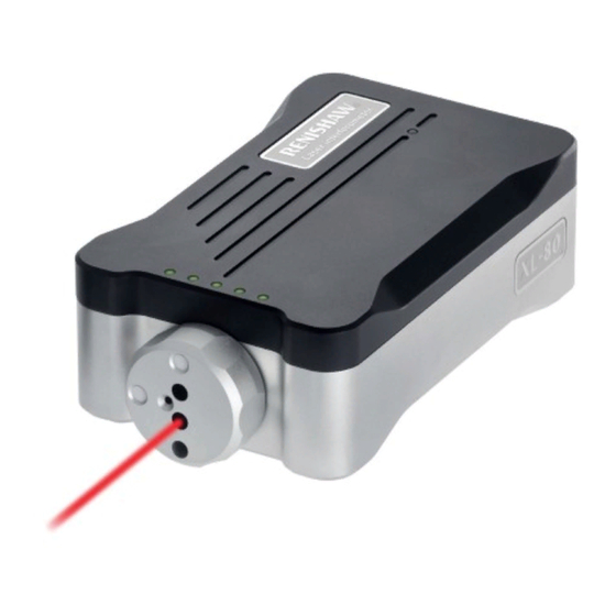
- Page 1 XL-80 laser system www.renishaw.com/xl80 #renishaw...
-
Page 2: Table Of Contents
Care and maintenance � � � � � � � � � � � � � � � � � � � � � � � � � � � � � � � � � � � � 48 XL80 laser system www�renishaw�com/xl80... - Page 3 Analogue signal output� � � � � � � � � � � � � � � � � � � � � � � � � � � � � � � � � � � � 61 XL80 laser system www.renishaw.com/xl80...
- Page 4 Visual alignment � � � � � � � � � � � � � � � � � � � � � � � � � � � � � � � � � � � � � � � � � 96 XL80 laser system www�renishaw�com/xl80...
- Page 5 A copy of the full EC Declaration of Conformity is available upon request� Renishaw warrants its equipment and software for a limited period (as set out in the Standard Terms and Conditions), provided that they are installed and used exactly as defined in associated Renishaw documentation.
- Page 6 Information to the user (47CFR: part 15.21) The user is cautioned that any changes or modifications not expressly approved by Renishaw plc or authorised representative could void the user’s authority to operate the equipment� Information to the user (47CFR: part 15.19) Special accessories (47CFR: part 15.27)
- Page 7 94/62/EC Packaging component Material code number The use of this symbol on Renishaw products and/or accompanying documentation indicates that the product Kit outer box Cardboard – 70% recycled content should not be mixed with general household waste upon XL-80 outer box Cardboard –...
-
Page 8: Safety Information
Do not remove any part of the housing; to do so could expose the user to high voltages and/or Class 3R laser radiation� CAUTION: Ensure that you read and understand the XL laser system user guide before using any XL laser system products� XL80 laser system www�renishaw�com/xl80... -
Page 9: Mechanical Safety
Do not use or handle the power supply unit if it comes into contact by the Renishaw software, it is the responsibility of the user to validate with fluids (for example, coolant), or if the case is cracked or otherwise these at low feedrate and be prepared to operate an emergency stop physically damaged�... - Page 10 XL-80 hardware #renishaw...
-
Page 11: System Overview
XL-80Q quadrature laser The XL-80 quadrature laser allows ‘raw’ interferometry signals to be supplied to custom-designed circuitry� This allows the laser to be used as a linear encoder system (not designed for closed loop feedback)�... -
Page 12: Xl Laser Controls And Indicators
NOTE: For full details on XC-80 operation and specification, refer to the XC-80 environmental compensator user guide (Renishaw part no� F-9908-0294)� XL80 laser system... -
Page 13: Tripod Stage
XL-80 Hardware XL-80 Hardware Linear Straightness XL-80 Applications Angular Tripod stage The stage and universal tripod provide a stable mounting for the XL laser, allowing it to be set up at different heights and giving full alignment control of the laser beam�... -
Page 14: Universal Tripod
XL-80 Hardware XL-80 Hardware Linear Straightness XL-80 Applications Angular Universal tripod Bubble level The tripod provides a stable mounting for the XL laser and allows the height The tripod stage kit is supplied with a bubble level� The bubble level is used to verify that the XL laser is level and for levelling the measurement optics�... -
Page 15: Linear Measurement Optics
XL-80 Hardware XL-80 Hardware Linear Straightness XL-80 Applications Angular Linear measurement optics Angular measurement optics The linear measurement optics are used for measuring linear The angular measurement optics are used to measure angular displacements, positional accuracy� particularly angular pitch and yaw� The angular displacement is achieved by measuring the difference between the angular interferometer and retroreflector. -
Page 16: Linear And Angular Optics Combination Kit
Optics mounting kit The linear and angular optics combination kit is a cost-effective option for The optics mounting kit is used to fit the Renishaw measurement optics to a users who only wish to perform these two measurements� It allows either CMM or machine tool�... -
Page 17: Straightness Measurement Optics Kit
XL-80 Hardware XL-80 Hardware Linear Straightness XL-80 Applications Angular Straightness measurement optics kit Flatness measurement kit The straightness measurement optics are used to measure straightness The flatness measurement kit is used to measure the flatness of surface errors in a linear axis� Straightness errors are displacements perpendicular plates and granite tables�... -
Page 18: Squareness Measurement Kit
XL-80 Hardware XL-80 Hardware Linear Straightness XL-80 Applications Angular Squareness measurement kit Large retroreflector This kit allows the measurement of the axis squareness (perpendicularity)� It must be used in conjunction with the straightness measurement optic� The large retroreflector is used to measure the straightness of vertical axes�... -
Page 19: Straightness Base
XL-80 Hardware XL-80 Hardware Linear Straightness XL-80 Applications Angular Adjustable turning mirror Swivel mirror The swivel mirror is used to deflect the laser beam in the The adjustable turning mirror vertical plane through the range is used for straightness 0 degrees to 135 degrees�... -
Page 20: Ls350 Laser Beam Steering Optic
XL-80 Hardware XL-80 Hardware Linear Straightness XL-80 Applications Angular LS350 laser beam steering optic Long-range linear accessory kit The long-range large retroreflector and periscope returns the measurement beam from the periscope to the laser at the correct displacement to enter the laser detector port�... -
Page 21: Small Linear Optics Kit
The pan and tilt adaptor can be used to: greater flexibility in mounting options. • mount the XL-80 laser on a tripod or magnetic base for applications such as slant bed lathes� • mount a retroreflector at an angle for convenient linear diagonal measurement�... -
Page 22: System Cases
Straightness XL-80 Applications Angular System cases Tripod cases Renishaw supplies storage cases in two sizes to protect the laser system A heavy-duty fabric case for safe storage and transportation from damage in storage and transit� of the Renishaw tripod� •... -
Page 23: Specifications
XL-80 Hardware XL-80 Hardware Linear Straightness XL-80 Applications Angular Specifications XL laser Laser source HeNe laser tube (Class II) Laser power < 1 mW Mode of operation Continuous-wave (CW) Nominal wavelength at Normal Temperature and Pressure (NTP)* 633 nm (nominal) - Page 24 XL-80 Hardware XL-80 Hardware Linear Straightness XL-80 Applications Angular Specifications System storage Mounting stage and laser – alignment adjustment Storage temperature range −25 °C to 70 °C Pitch range ±1�5 ° Storage humidity range 0 %RH to 95 %RH non-condensing Yaw range ±1�5 °...
- Page 25 XL-80 Hardware XL-80 Hardware Linear Straightness XL-80 Applications Angular Specifications Linear measurement Standard range 0 m to 80 m Accuracy (with XC compensator) ±0�5 ppm* Resolution 0�001 µm Maximum velocity 240 m/min (4 m/s) Note: The accuracy values do not include the errors associated with the normalisation of the readings to a material temperature of 20 °C...
- Page 26 XL-80 Hardware XL-80 Hardware Linear Straightness XL-80 Applications Angular Specifications Straightness measurement Short range 0�1 m to 4�0 m Axial range Long range 1 m to 30 m Straightness measurement range ±2�5 mm Short range ±0�5% ±0�5 ±0�15M µm Accuracy Long range ±2�5% ±5 ±0�015M...
- Page 27 XL-80 Hardware XL-80 Hardware Linear Straightness XL-80 Applications Angular Specifications Flatness measurement Axial range 0 m to 15 m Flatness measurement range ±1�5 mm Accuracy ±0�6% ±0�02M µm 0�02 µm for 150 mm base Resolution 0�01 µm for 50 mm and 100 mm base...
-
Page 28: Dimensions And Weights
XL-80 Hardware XL-80 Hardware Linear Straightness XL-80 Applications Angular Dimensions and weights 214 mm 190 mm 9 mm XL-80 laser 70 mm 65 mm Weight 1�85 kg 12 mm 25 mm 160 mm 10 mm 3 POS’N XL80 laser system... - Page 29 XL-80 Hardware XL-80 Hardware Linear Straightness XL-80 Applications Angular Tripod stage XC environmental compensation 184 mm 160 mm 77 mm 135 mm Weight 0�49 kg Air temperature sensor Material temperature sensor 33 mm 17 mm 17 mm 36 mm 36 mm...
- Page 30 XL-80 Hardware XL-80 Hardware Linear Straightness XL-80 Applications Angular Linear measurement optics Angular measurement optics Linear reflector Angular interferometer 15 mm 28 mm 28 mm 6 mm 28 mm M3 thread M3 thread 38 mm 37 mm 28 mm 19�8 mm...
- Page 31 XL-80 Hardware XL-80 Hardware Linear Straightness XL-80 Applications Angular Flatness measurement optics Straightness measurement optics (short and long range) Flatness mirror Straightness interferometer M8 thread White alignment lines Tilt adjustment 9 mm Mirror 18 mm 19 mm 42 mm 48 mm...
- Page 32 XL-80 Hardware XL-80 Hardware Linear Straightness XL-80 Applications Angular Large retroreflector Straightness base 81 mm M8 thread (4 positions) (on rear face) 70 mm 28 mm 88 mm 6 mm 124 mm 28 mm 14 mm Ø80 mm M8 thread...
- Page 33 XL-80 Hardware XL-80 Hardware Linear Straightness XL-80 Applications Angular Squareness measurement optics Optical square Bracket for optical square M3 thread 63 mm 21 mm 46 mm Centre Line 54 mm 7 mm 46 mm 22 mm 62 mm 33 mm...
- Page 34 XL-80 Hardware XL-80 Hardware Linear Straightness XL-80 Applications Angular Optics mounting kit Clamp block Base plate 38 mm M8 thread 58 mm 50 mm 6 mm 37 mm 63 mm 51 mm 75 mm 14 mm 28 mm 4 mm...
- Page 35 XL-80 Hardware XL-80 Hardware Linear Straightness XL-80 Applications Angular Accessories Fixed turning mirror Swivel mirror 70 mm 60 mm 38 mm 38 mm M3 thread (16 positions) 38 mm M8 thread thro’ 38 mm 28 mm 60 mm Weight 110 g...
-
Page 36: Full Xl System Case
XL-80 Hardware XL-80 Hardware Linear Straightness XL-80 Applications Angular Full XL system case × 2 (tray removed) × 2 × 4 × 2 × 2 XL80 laser system www.renishaw.com/xl80... - Page 37 XL-80 Hardware XL-80 Hardware Linear Straightness XL-80 Applications Angular Full system case (tray) × 3 × 4 XL80 laser system www�renishaw�com/xl80...
-
Page 38: Full Xl System Contents
Full XL system contents Index Part number Part name Includes Part number Index XL-80 laser Universal power supply A-9908-0299 A-9908-0405 XL-80 laser kit USB cable A-9908-0286 Laser software kit A-9908-0201 Not shown AUX/I/O connector A-9908-0329 Not shown XL tripod stage A-9908-0700... -
Page 39: Full Xl System Contents (Additional Items)
XL-80 Hardware XL-80 Hardware Linear Straightness XL-80 Applications Angular Full XL system contents (additional items) Index Part number Part name Includes Part number Index Optical square Bracket squareness optic M-8003-1680 A-8003-0665 Squareness measurement optics Cap head screw (× 4) Hexagonal key Flatness mirror (×... -
Page 40: Base Xl System Case
XL-80 Hardware XL-80 Hardware Linear Straightness XL-80 Applications Angular Base XL system × 2 case × 3 × 4 XL80 laser system www.renishaw.com/xl80... -
Page 41: Base Xl System Case Contents
Base XL system case contents Index Part number Part name Includes Part number Index XL-80 laser Universal power supply A-9908-0299 A-9908-0405 XL-80 laser kit USB cable A-9908-0286 Laser software kit A-9908-0201 Not shown AUX I/O connector A-9908-0329 Not shown XL tripod stage A-9908-0700... -
Page 42: Diagnostics And Troubleshooting
Check laser beam is present� Solid red Beam break – measurements cannot be made� • If no laser beam, power cycle� • If issue persists, contact local Renishaw office. • Check laser alignment� Solid amber Beam low – danger of beam break occurring� •... -
Page 43: Laser Status Led Info
Actions • Check laser beam is present� Solid red Error • Power cycle the laser� • If issue persists, contact local Renishaw office. • Check laser alignment� Solid amber Laser unstable • If issue persists, power cycle� • If issue persists, contact local Renishaw office. -
Page 44: Common Causes Of Laser Destabilisation
XL-80 Hardware XL-80 Hardware Linear Straightness XL-80 Applications Angular Common causes of laser destabilisation Back reflections Ambient temperature change The feedback circuit which controls the heater and thus stabilises the laser is If the XL laser has been kept in a cold place (for example, stored in the boot based on monitoring the output beam from the laser tube�... -
Page 45: Care And Handling
Recalibration periods The Renishaw recommended recalibration period for an XL laser is 3 years� Recalibration NOTE: This is 3 years from sale by Renishaw rather than from factory Why recalibrate? calibration date as stated on the calibration certificates supplied with the... - Page 46 Recalibration facilities Recalibration of the XL laser requires specialist test rigs and software to give results comparable to the original factory calibration� Renishaw therefore recommends that items are returned to our specialist facilities via your local Renishaw office.
-
Page 47: Xl Laser Calibration
Calibration certificate Each XL laser is delivered with a calibration certificate. This demonstrates that the system has been calibrated at the Renishaw factory against reference systems with traceability to National Standards� It is proof of the equipment’s performance as tested before delivery� Visit the Calibration product quality and conformance webpage for more information�... -
Page 48: Care And Maintenance
XL-80 Hardware XL-80 Hardware Linear Straightness XL-80 Applications Angular Care and maintenance Optics Care of small linear optics kit Cleaning of the optics should be a last resort If contamination of the optical surfaces is suspected, undo the four cap screws holding the optics cartridge within the housing�... -
Page 49: Auxiliary Input/Output
XL-80 Hardware XL-80 Hardware Linear Straightness XL-80 Applications Angular Appendix A Auxiliary Input/Output connector kit An auxiliary I/O connector kit is provided with the XL laser kit to enable users Auxiliary Input/Output to configure cable connections for use with the XL laser’s auxiliary I/O port. -
Page 50: Dip Switch Settings
XL-80 Hardware XL-80 Hardware Linear Straightness XL-80 Applications Angular DIP switch settings There are four DIP switches on the back of the XL laser, each of which can be ON (rocker up position) or OFF (rocker down position)� The table below summarises the DIP switch settings�... -
Page 51: Auxiliary I/O Connector
XL-80 Hardware XL-80 Hardware Linear Straightness XL-80 Applications Angular Auxiliary I/O connector Pin number Function Reserved – do not connect Analogue position voltage output Reserved – do not connect Reserved – do not connect /B output* B output* Reserved – do not connect Reserved –... -
Page 52: Remote Triggering
XL-80 Hardware XL-80 Hardware Linear Straightness XL-80 Applications Angular Appendix B Remote triggering +3.3 V The remote trigger facility allows data to be captured by the calibration 10 K Fast trigger input Pin 14 software, upon receipt of a trigger signal generated remotely, for example, from a machine under test�... -
Page 53: Slow Trigger
XL-80 Hardware XL-80 Hardware Linear Straightness XL-80 Applications Angular Slow trigger The XL laser is triggered using a noisier trigger signal; for example, from a +3.3 V relay or switch as shown opposite� This signal is applied to the slow trigger pin of the auxiliary I/O port�... -
Page 54: Quadrature Output
XL-80 Hardware XL-80 Hardware Linear Straightness XL-80 Applications Angular Appendix C Format These signals are not compensated for changes in the refractive index of Quadrature output air� The A, /A, B, /B, ALARMOUT and /ALARMOUT signals are provided in RS422 balanced differential line format�... -
Page 55: Direction Sign Convention
XL-80 Hardware XL-80 Hardware Linear Straightness XL-80 Applications Angular Direction sign convention Update rate The quadrature output update rate is 20 MHz� Accuracy The transitions of the quadrature signals are accurate to within ±10 nm at low velocities� However, there is a very small propagation delay (D) between a change in the optic position and in the quadrature output�... -
Page 56: Alarm Conditions
XL-80 Hardware XL-80 Hardware Linear Straightness XL-80 Applications Angular Alarm conditions The alarm lines will go active (ALARMOUT high, /ALARMOUT low) and latch +3.3 V in the following situations: • The XL laser internal counter allows a movement of more than ±169�9 m 10 K (231 ×... -
Page 57: Rs422 Receiver Circuitry
XL-80 Hardware XL-80 Hardware Linear Straightness XL-80 Applications Angular RS422 receiver circuitry Hysteresis The image below shows a recommended circuit for the user end of RS422 Electrical noise or axis vibration can cause multiple edges to appear at each receivers� A, B and ALARMOUT signals should be DC terminated with a 100 quadrature transition as shown below, even when stationary�... -
Page 58: Suggested Extraction Of Valid Data
XL-80 Hardware XL-80 Hardware Linear Straightness XL-80 Applications Angular Suggested extraction of valid data The circuit shown below can be used to extract valid quadrature� The clock The maximum velocities possible are 1�6 m/s for 80 nm quadrature and frequency should be selected according to the maximum velocity to be 0�2 m/s for 10 nm quadrature�... -
Page 59: Xl-80Q Operation With Rcu10
XL-80 Hardware XL-80 Hardware Linear Straightness XL-80 Applications Angular XL-80Q operation with RCU10 XL-80Q set-up: XL-80Q RCU10 XL-80Q DIP switch 2 must be set for appropriate quadrature resolution Pin number Signal Signal Pin Number “ON” = ≈10 nm resolution (λ/64) “OFF”... - Page 60 XL-80 Hardware XL-80 Hardware Linear Straightness XL-80 Applications Angular RCU10 configuration Below are the configuration settings for the RCU10 to XL-80Q. These settings are configured on the RCU10 using the RCU-CS software. For full details please consult the RCU10 installation manual�...
-
Page 61: Analogue Signal Output
XL-80 Hardware XL-80 Hardware Linear Straightness XL-80 Applications Angular Analogue signal output The analogue signal output facility outputs a voltage which is proportional to The dynamic range of the analogue output is ± 5 V� An accuracy of ±2% is the displacement of the measurement optics�... - Page 62 XL-80 Hardware XL-80 Hardware Linear Straightness XL-80 Applications Angular Electrical performance specification Output voltage range ±5 V 10 K Pin 16 Datum input Accuracy (over ± 4�5 V range) ±2% of full scale Datum input protected Rollover limit ±40 mm to ±...
- Page 63 XL-80 applications #renishaw...
-
Page 64: Introduction
XL-80 Hardware Linear Straightness XL-80 Applications XL-80 Applications Angular Introduction Aims of the guide • Provide the reader with the skills and confidence necessary to perform measurements using the XL laser system� • Highlight the factors affecting measurements and methods of reducing/ eliminating them�... - Page 65 XL-80 Hardware Linear Straightness XL-80 Applications XL-80 Applications Angular Introduction Measurement modes This guide includes: Linear Linear measurement is the most common measurement mode performed with a laser� Any inaccuracy from the commanded position in a position critical motion system is often caused by factors such as changes in environmental conditions, mechanical wear, or angular pitch and yaw.
-
Page 66: Measurement Considerations
XL-80 Hardware Linear Straightness XL-80 Applications XL-80 Applications Angular Measurement considerations Alignment Correct alignment of the laser is essential to provide an accurate measurement� Basic alignment rules are shown on the following pages; further alignment steps for each measurement type are detailed in each section�... -
Page 67: Carto Software Suite
XL-80 Hardware Linear Straightness XL-80 Applications XL-80 Applications Angular CARTO software suite The XL system is used with the CARTO software suite� This is made up of three applications: Capture collects laser interferometry data Explore enables powerful analysis to international standards... -
Page 68: Basic Set-Up
XL-80 Hardware Linear Straightness XL-80 Applications XL-80 Applications Angular Basic set-up Setting up the tripod Place the bubble level onto the tripod boss� Adjust the tripod legs to ensure that the bubble is level� NOTE: The height of the tripod should be set to approximately the height of the machine bed/optics�... - Page 69 XL-80 Hardware Linear Straightness XL-80 Applications XL-80 Applications Angular Basic set-up Attaching the laser to the tripod 1� Attach the laser to the tripod stage using Place the bubble level on top of the XL laser and Connect the XL laser to the PC via the USB cable�...
- Page 70 XL-80 Hardware Linear Straightness XL-80 Applications XL-80 Applications Angular Laser preparation Set all laser stage adjustments to the mid-positions� Height adjustment Horizontal translation adjustment XL80 laser system www�renishaw�com/xl80...
-
Page 71: Set-Up Of The Xc Compensator
XL-80 Hardware Linear Straightness XL-80 Applications XL-80 Applications Angular Set-up of the XC compensator NOTE: The XC80 should only Attach the XC environmental Connect the air and material sensors to the XC be orientated horizontally (as compensator to the machine�... -
Page 72: Basic Rules Of Alignment
XL-80 Hardware Linear Straightness XL-80 Applications XL-80 Applications Angular Basic rules of alignment Near field adjustment – when the moving retroreflector is closest to the stationary optic. Method 1: Translate tripod� Method 2: Translate the machine axes� XL80 laser system... - Page 73 XL-80 Hardware Linear Straightness XL-80 Applications XL-80 Applications Angular Basic rules of alignment Far field adjustment – when the moving retroreflector is furthest from the stationary optic. Adjust the pitch and yaw screws on the laser and tripod stage� XL80 laser system...
-
Page 74: Linear Measurement
XL-80 Hardware Linear Linear Straightness XL-80 Applications XL-80 Applications Angular Linear measurement XL80 laser system www�renishaw�com/xl80... -
Page 75: Mounting The Optics
XL-80 Hardware Linear Linear Straightness XL-80 Applications XL-80 Applications Angular Mounting the optics The linear measurement set-up� XL80 laser system www.renishaw.com/xl80... - Page 76 XL-80 Hardware Linear Linear Straightness XL-80 Applications XL-80 Applications Angular Mounting the optics Mounting the retroreflector The linear measurement set-up� Reduced beam aperture Target Assemble the retroreflector assembly as shown. Attach the target onto the face of the Rotate the laser shutter to emit a reduced Mount to the moving element of the machine�...
- Page 77 XL-80 Hardware Linear Linear Straightness XL-80 Applications XL-80 Applications Angular Mounting the optics Mounting the retroreflector The linear measurement set-up� Drive the retroreflector to the ‘near field’ position. Adjust the beam to the centre of the white target Remove the target and check that the returned using the translation screws�...
- Page 78 XL-80 Hardware Linear Linear Straightness XL-80 Applications XL-80 Applications Angular Mounting the optics Mounting the interferometer The linear measurement set-up� < 10 mm Assemble the interferometer assembly as shown� Attach the target to the input aperture and align Mount to the stationary element of the machine: it with the beam�...
-
Page 79: Visual Alignment
XL-80 Hardware Linear Linear Straightness XL-80 Applications XL-80 Applications Angular Visual alignment Mounting the linear interferometer The linear measurement set-up� Remove the target� Ensure that the two return beams are overlapping on the shutter target� Adjust as required� XL80 laser system... - Page 80 XL-80 Hardware Linear Linear Straightness XL-80 Applications XL-80 Applications Angular Visual alignment Use the machine to move the reflector away from the interferometer� Stop if the beam drifts past the edge of the target shutter� Adjust the pitch and yaw so the beam hits the centre of the target�...
- Page 81 XL-80 Hardware Linear Linear Straightness XL-80 Applications XL-80 Applications Angular Visual alignment Remove the target� Ensure that the two return beams are overlapping Rotate the XL laser shutter to the open position on the shutter target� Use the tripod height ready for data capture�...
-
Page 82: Linear Measurement
XL-80 Hardware Linear Linear Straightness XL-80 Applications XL-80 Applications Angular Linear measurement With LS350 laser beam steerer XL80 laser system www�renishaw�com/xl80... -
Page 83: Mounting The Optics
XL-80 Hardware Linear Linear Straightness XL-80 Applications XL-80 Applications Angular Mounting the optics An overview of the linear measurement set-up with beam steerer� XL80 laser system www.renishaw.com/xl80... - Page 84 XL-80 Hardware Linear Linear Straightness XL-80 Applications XL-80 Applications Angular Mounting the optics Mounting the retroreflector The linear measurement set-up� Reduced beam aperture Target Assemble the retroreflector assembly as shown. Attach the target onto the face of the Rotate the laser shutter to emit a reduced Mount to the moving element of the machine�...
- Page 85 XL-80 Hardware Linear Linear Straightness XL-80 Applications XL-80 Applications Angular Mounting the optics Mounting the retroreflector Drive the retroreflector to the near field position. Adjust the beam to the centre of the white target Remove the target and check that the returned using the translation screws�...
- Page 86 XL-80 Hardware Linear Linear Straightness XL-80 Applications XL-80 Applications Angular Mounting the optics Mounting the linear interferometer < 10 mm Assemble the interferometer assembly and mount Attach the target to the beam steerer and align it Mount to the stationary element of the machine: the beam steerer onto the input face of the beam with the beam�...
-
Page 87: Visual Alignment
XL-80 Hardware Linear Linear Straightness XL-80 Applications XL-80 Applications Angular Visual alignment Mounting the linear interferometer� Remove the target� Ensure that the two return beams are overlapping on the shutter target� Adjust as required� XL80 laser system www.renishaw.com/xl80... - Page 88 XL-80 Hardware Linear Linear Straightness XL-80 Applications XL-80 Applications Angular Visual alignment Visual alignment Use the machine to move the reflector away from the interferometer� Stop if the beam drifts past the edge of the target shutter� Adjust the beam steerer so...
- Page 89 XL-80 Hardware Linear Linear Straightness XL-80 Applications XL-80 Applications Angular Visual alignment Remove the target� Ensure that the two return beams are overlapping Rotate the XL laser shutter to the open position on the shutter target� Use the tripod height ready for data capture�...
-
Page 90: Angular Measurement (Pitch/Yaw)
XL-80 Hardware Linear Straightness XL-80 Applications XL-80 Applications Angular Angular Angular measurement (pitch/yaw) NOTE: Environmental compensation is not necessary when taking angular measurements, therefore, the XC environmental compensator and environmental sensors are not required� XL80 laser system www�renishaw�com/xl80... -
Page 91: Mounting The Optics
XL-80 Hardware Linear Straightness XL-80 Applications XL-80 Applications Angular Angular Mounting the optics The pitch/yaw measurement set-ups – horizontal axis� Pitch angle Yaw angle XL80 laser system www.renishaw.com/xl80... - Page 92 XL-80 Hardware Linear Straightness XL-80 Applications XL-80 Applications Angular Angular Mounting the optics The pitch/yaw measurement set-ups – vertical axis� Pitch angle Yaw angle XL80 laser system www�renishaw�com/xl80...
- Page 93 XL-80 Hardware Linear Straightness XL-80 Applications XL-80 Applications Angular Angular Mounting the optics Mounting the retroreflector Reduced beam aperture Target Assemble the retroreflector assembly as shown. Attach the target onto the face of the Rotate the laser shutter to emit a reduced Mount to the moving element of the machine�...
- Page 94 XL-80 Hardware Linear Straightness XL-80 Applications XL-80 Applications Angular Angular Mounting the optics Mounting the retroreflector Drive the angular retroreflector to the near Adjust the beam to the centre of the white target Remove the target and check that the returned field position.
- Page 95 XL-80 Hardware Linear Straightness XL-80 Applications XL-80 Applications Angular Angular Mounting the optics Mounting the angular interferometer Pitch Assemble the interferometer assembly as shown� Attach the target to input aperture and align it Mount to the stationary element of the machine: with the beam�...
-
Page 96: Visual Alignment
XL-80 Hardware Linear Straightness XL-80 Applications XL-80 Applications Angular Angular Visual alignment Mounting the angular interferometer The angular measurement set-up� Remove the target� Check that the returned beam hits the centre of the target on the XL laser shutter� If it does not, adjust the position of the interferometer�... - Page 97 XL-80 Hardware Linear Straightness XL-80 Applications XL-80 Applications Angular Angular Visual alignment Use the machine to move the reflector away from the interferometer� Stop if the beam drifts past the edge of the target shutter� Adjust the pitch and yaw so the beam hits the centre of the target�...
- Page 98 XL-80 Hardware Linear Straightness XL-80 Applications XL-80 Applications Angular Angular Visual alignment Remove the target from the retroreflector. Ensure that the two return beams are overlapping Rotate the shutter to an open position, and check on the shutter target� Use the tripod height...
-
Page 99: With Ls350 Laser Beam Steerer
XL-80 Hardware Linear Straightness XL-80 Applications XL-80 Applications Angular Angular Angular measurement (pitch/yaw) With LS350 laser beam steerer XL80 laser system www.renishaw.com/xl80... -
Page 100: Mounting The Optics
XL-80 Hardware Linear Straightness XL-80 Applications XL-80 Applications Angular Angular Mounting the optics The pitch/yaw measurement set-ups – horizontal axis� Pitch angle Yaw angle XL80 laser system www�renishaw�com/xl80... - Page 101 XL-80 Hardware Linear Straightness XL-80 Applications XL-80 Applications Angular Angular Mounting the optics The pitch/yaw measurement set-ups – vertical axis� Pitch angle Yaw angle XL80 laser system www.renishaw.com/xl80...
- Page 102 XL-80 Hardware Linear Straightness XL-80 Applications XL-80 Applications Angular Angular Mounting the optics Mounting the angular retroreflector Reduced beam aperture Pitch Pitch Target Assemble the retroreflector assembly as shown. Attach the target onto the face of the Rotate the laser shutter to emit a reduced Mount to the moving element of the machine�...
- Page 103 XL-80 Hardware Linear Straightness XL-80 Applications XL-80 Applications Angular Angular Mounting the optics Mounting the angular retroreflector Drive the retroreflector to the near field position. Adjust the beam to the centre of the white target Remove the target and check that the returned using the translation screws�...
- Page 104 XL-80 Hardware Linear Straightness XL-80 Applications XL-80 Applications Angular Angular Mounting the optics Mounting the angular interferometer Pitch Assemble the interferometer assembly and mount Mount to the stationary element of the machine: Attach the target to input aperture and align it the beam steerer onto the input face of the beam with the beam�...
-
Page 105: Visual Alignment
XL-80 Hardware Linear Straightness XL-80 Applications XL-80 Applications Angular Angular Visual alignment Mounting the angular interferometer The angular measurement set-up� Remove the target� Check that the returned beam hits the centre of the target on the XL laser shutter� If it does not, adjust the position of the interferometer�... - Page 106 XL-80 Hardware Linear Straightness XL-80 Applications XL-80 Applications Angular Angular Visual alignment Use the machine to move the reflector away from the interferometer� Stop if the beam drifts past the edge of the target shutter� Adjust the beam steerer so the beam hits the centre of the target�...
- Page 107 XL-80 Hardware Linear Straightness XL-80 Applications XL-80 Applications Angular Angular Visual alignment Remove the target from the retroreflector. Ensure that the two return beams are overlapping Rotate the XL laser shutter to the open position on the shutter target� Use the tripod height ready for data capture�...
-
Page 108: (Horizontal Axis - Horizontal Plane)
XL-80 Hardware Linear Straightness Straightness XL-80 Applications XL-80 Applications Angular Straightness measurement (horizontal axis – horizontal plane) NOTE: Environmental compensation is not necessary when taking straightness measurements, therefore, the XC environmental compensator and environmental sensors are not required� XL80 laser system... -
Page 109: Mounting The Optics
XL-80 Hardware Linear Straightness Straightness XL-80 Applications XL-80 Applications Angular Mounting the optics Horizontal measurement plane XL80 laser system www.renishaw.com/xl80... -
Page 110: Horizontal Axis
XL-80 Hardware Linear Straightness Straightness XL-80 Applications XL-80 Applications Angular Horizontal axis Horizontal measurement plane Reduced Target beam aperture Attach the straightness shutter to the laser in the Rotate the black bezel of the laser shutter� Continue rotating until a reduced diameter beam orientation shown�... -
Page 111: Mounting The Optics
XL-80 Hardware Linear Straightness Straightness XL-80 Applications XL-80 Applications Angular Mounting the optics Mounting the straightness reflector Assemble the straightness reflector as Attach the target to the centre of the straightness Mount to the stationary element of the machine shown above�... - Page 112 XL-80 Hardware Linear Straightness Straightness XL-80 Applications XL-80 Applications Angular Mounting the optics Mounting the straightness interferometer Assemble the straightness interferometer Mount to the moving element of the machine� Ensure that the target on the straightness assembly as shown� interferometer is in the same orientation as the reflector.
- Page 113 XL-80 Hardware Linear Straightness Straightness XL-80 Applications XL-80 Applications Angular Mounting the optics Mounting the straightness interferometer Mount to the stationary element of the machine: Drive the interferometer to the near field position. Translate the machine until the beam is on the white target�...
-
Page 114: Visual Alignment
XL-80 Hardware Linear Straightness Straightness XL-80 Applications XL-80 Applications Angular Visual alignment Drive the interferometer towards the retroreflector. Stop if the beam drifts past the edge of the target shutter� Adjust the pitch and yaw so that the beam hits the centre of the target�... - Page 115 XL-80 Hardware Linear Straightness Straightness XL-80 Applications XL-80 Applications Angular Visual alignment Outward beam Position the interferometer halfway along the axis Rotate the face of the interferometer so that the The beams should hit the straightness reflector of travel� beam passes through the top of the aperture�...
- Page 116 XL-80 Hardware Linear Straightness Straightness XL-80 Applications XL-80 Applications Angular Visual alignment Return beam alignment Outward beam Return beam Ensure that the returned beam from the reflector If the return beam is to the left or right of the enters the centre line of the interferometer�...
- Page 117 XL-80 Hardware Linear Straightness Straightness XL-80 Applications XL-80 Applications Angular Visual alignment Straightness shutter Reduced Both return beam aperture beams on target Ensure that the two laser beams are overlapping If the beams are not overlapping, finely rotate Rotate the shutter until the 6 mm beam is emitted�...
-
Page 118: Straightness Measurement
XL-80 Hardware Linear Straightness Straightness XL-80 Applications XL-80 Applications Angular Straightness measurement (horizontal axis – vertical plane) XL80 laser system www.renishaw.com/xl80... -
Page 119: Mounting The Optics
XL-80 Hardware Linear Straightness Straightness XL-80 Applications XL-80 Applications Angular Mounting the optics The straightness measurement set-ups – along a horizontal axis� Horizontal measurement plane XL80 laser system www�renishaw�com/xl80... - Page 120 XL-80 Hardware Linear Straightness Straightness XL-80 Applications XL-80 Applications Angular Mounting the optics Horizontal axis – vertical measurement plane Reduced Target beam aperture Attach the straightness shutter to the laser in the Rotate the black bezel of the laser shutter�...
- Page 121 XL-80 Hardware Linear Straightness Straightness XL-80 Applications XL-80 Applications Angular Mounting the optics Mounting the straightness reflector Assemble the straightness reflector as shown. Attach the target to the centre of the Mount to the stationary element of the machine straightness reflector.
- Page 122 XL-80 Hardware Linear Straightness Straightness XL-80 Applications XL-80 Applications Angular Mounting the optics Mounting the straightness interferometer Assemble the interferometer assembly as shown� Mount to the moving element of the machine� Rotate the interferometer so that the white target is in the same orientation as the target on the reflector.
- Page 123 XL-80 Hardware Linear Straightness Straightness XL-80 Applications XL-80 Applications Angular Mounting the optics Mounting the straightness interferometer Mount to the stationary element of the machine: Drive the interferometer to the near field position. Translate the machine until the beam is on the white target�...
-
Page 124: Visual Alignment
XL-80 Hardware Linear Straightness Straightness XL-80 Applications XL-80 Applications Angular Visual alignment Drive the interferometer towards the retroreflector. Stop if the beam drifts past the edge of the � target shutter Adjust the pitch and yaw so that the beam hits the centre of the target�... - Page 125 XL-80 Hardware Linear Straightness Straightness XL-80 Applications XL-80 Applications Angular Visual alignment 6 mm Outward beam Position the interferometer halfway along the axis Rotate the face of the interferometer so that The beams should hit the straightness reflector of travel�...
- Page 126 XL-80 Hardware Linear Straightness Straightness XL-80 Applications XL-80 Applications Angular Visual alignment Return beam alignment Return Outward beam beam Ensure that the returned beam from the reflector If the return beam is above or below the enters the centre line of the interferometer�...
- Page 127 XL-80 Hardware Linear Straightness Straightness XL-80 Applications XL-80 Applications Angular Visual alignment Straightness shutter Reduced Both return beam aperture beams on target Ensure that the two laser beams are overlapping If the beams are not overlapping, finely rotate Rotate the shutter until the 6 mm beam is emitted�...
- Page 128 +44 (0) 1453 524524 uk@renishaw.com © 2020–2022 Renishaw plc. All rights reserved. This document may not be copied or reproduced in whole or in part, or transferred to any other WHILE CONSIDERABLE EFFORT WAS MADE TO VERIFY THE ACCURACY OF THIS media or language by any means, without the prior written permission of Renishaw.
Need help?
Do you have a question about the XL-80 and is the answer not in the manual?
Questions and answers