Table of Contents
Advertisement
Quick Links
Advertisement
Table of Contents

Subscribe to Our Youtube Channel
Related Manuals for Renishaw OMP600


Summary of Contents for Renishaw OMP600
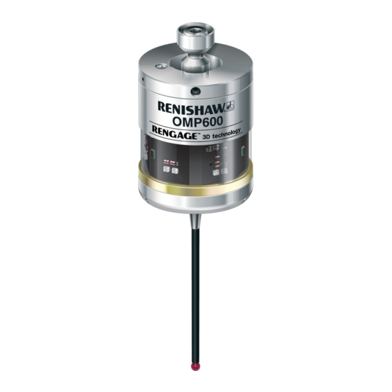
- Page 1 Installation guide H-5180-8504-01-B OMP600 high-accuracy optical machine probe...
- Page 2 This document may not be copied or reproduced in whole or in part, or transferred to any other media or language, by any means, without the prior written permission of Renishaw plc. Renishaw plc. Registered in England and Wales. Company no: 1106260. Registered office: New Mills, Wotton-under-Edge, Gloucestershire, GL12 8JR, UK.
-
Page 3: Table Of Contents
OMP600 specification ........ - Page 4 Preparing the OMP600 for use ........
-
Page 5: Before You Begin
Renishaw office. Renishaw warrants its equipment and software for a limited period (as set out in the Standard Terms and Conditions), provided that they are installed and used exactly as defined in associated Renishaw documentation. -
Page 6: Cnc Machines
Care of the probe Keep system components clean and treat the probe as a precision tool. Patents Features of the OMP600 probe, and other similar Renishaw probes, are the subject of one or more of the following patents and/or patent applications: CN 100416216... -
Page 7: Safety
Ensure that you comply with international and national battery transport regulations when transporting batteries or this product with the batteries inserted To reduce the risk of shipment delays, should you need to return this product to Renishaw for any reason, do not return any batteries. Information to the machine supplier/ installer... - Page 8 The product was evaluated and classified using the following standard: BS EN 62471:2008 The photobiological safety of lamps and lamp systems. Renishaw recommends that you do not stare at or look directly into any LED device, irrespective of its risk clarification.
-
Page 9: Omp600 Basics
Performing this calibration for every 3D direction can be time-consuming. The OMP600 has almost no pre-travel variation, so a single calibration value may be used for any probing angle in 2D or 3D. This results in a vastly reduced calibration time. An additional benefit is a corresponding reduction in errors introduced by environmental changes within the machine during a long calibration cycle. -
Page 10: Getting Started
To operate a twin OMP600 probe system, one OMP600 probe needs to be set to PROBE 1 start and the other to PROBE 2 start. In applications where a third OMP600 is to be used, this should be set to PROBE 3 start. -
Page 11: Probe Modes
Switch-on delay When the standard switch-on is selected, the probe will be operational in less than 0.8 seconds. After being switched on, the OMP600 must remain operational for a minimum of 1 second before being switched off. A second switch-on mode is available whereby a 3 second delay is invoked after the probe start signal is received. -
Page 12: Switch-On / Switch-Off Methods
NOTE: A visual indication of currently selected probe settings is provided, on battery insertion, by the three multicoloured LEDs located within the probe’s window (see Section 4, “Trigger Logic™”). NOTE: After being switched on, the OMP600 must be on for 1 second before being switched off. OMP600 switch-on method... -
Page 13: Enhanced Trigger Filter
In previous strain gauge products, the probe was required to be turned off during reorientation moves. The auto-reset function in the OMP600 can compensate for stylus forces, resulting from changes in probe orientation, that can cause the probe to trigger. -
Page 14: Optical Power
Dotted lines on the performance envelopes represent the OMP600 in low optical power. Low optical power should be used whenever possible for increased battery life. -
Page 15: Omp600 Specification
OMP600 specification Principal application Workpiece inspection and job set-up on all sizes of machining centres and small to medium multi-tasking machines. Dimensions Length 76 mm (2.99 in) Diameter 63 mm (2.48 in) Weight (without shank) With batteries 1029 g (36.30 oz) Without batteries 964 g (34.00 oz) - Page 16 OMP600 installation guide Environment IP rating IPX8, BS EN 60529:1992+A2:2013 IK rating IK01, BS EN 62262:2002+A1:2021 [for glass window] Storage temperature -25 °C to +70 °C (-13 °F to +158 °F) Operating temperature +5 °C to +55 °C (+41 °F to +131 °F) Battery types 2 ×...
-
Page 17: Typical Battery Life
Typical battery life Modulated transmission 2 × AA 1.5V Optical on/off Shank on/off Spin on/off alkaline Standard Standard Standard batteries power power power power power power (typical) Standby 480 days 520 days 170 days 5% usage 80 days 100 days 90 days 100 days 60 days... -
Page 18: Recommended Styli
Use of the solid carbon fibre styli featured above will guarantee the best possible measurement performance from the OMP600. It is possible that the recommended styli may not be suitable for every OMP600 application and it may be necessary to select specialised styli configurations to meet specific application requirements. -
Page 19: System Installation
Operating envelopes When used with the OMI or the OMM with MI 12 or MI 12-B, the OMP600 uses legacy transmission. When used with the OMI-2, OMI-2T, OMI-2H or with the OSI with OMM-2 interface system, the OMP600 uses modulated transmission. - Page 20 Performance envelope when using the OMP600 with an OMI-2, OMI-2T, OMI-2H or OMM-2 (modulated transmission) The diodes of the OMP600 and the OMI-2, OMI-2T, OMI-2H or OMM-2 must be in each other’s field of view and within the performance envelope shown. The OMP600 performance envelope is based on the optical centre line of the OMI-2, OMI-2T, OMI-2H or OMM-2 being at 0°...
- Page 21 Performance envelope when using the OMP600 with an OMI-2C (modulated transmission) The diodes of both the OMP600 and the OMI-2C must be in each other’s field of view, and within the performance envelope shown. The OMP600 performance envelope is based on the optical centre line of the OMI-2C being at 0°...
-
Page 22: Preparing The Omp600 For Use
OMP600 installation guide Preparing the OMP600 for use Fitting the stylus 1.8 Nm - 2.2 Nm 1.8 Nm – 2.2 Nm (1.3 lbf.ft - 1.6 lbf.ft) (1.3 lbf.ft – 1.6 lbf.ft) M-5000-3707 M-5000-3707... -
Page 23: Installing The Batteries
Installing the batteries NOTES: See Section 5, “Maintenance” for a list of suitable battery types. If dead batteries are inadvertently inserted, the LEDs will remain a constant red. Do not allow coolant or debris to enter the battery compartment. When inserting batteries, check that the battery polarity is correct. -
Page 24: Mounting The Probe On A Shank
Mounting the probe on a shank NOTE: In instances where the OMP600 is to be used with a shank switch, it will be necessary to remove the plug from the rear of the probe using pliers. This should then be substituted with the bobbin (A-4038-0303). -
Page 25: Stylus On-Centre Adjustment
Stylus on-centre adjustment NOTES: During adjustment, take care not to rotate the probe relative to the shank as this can damage the bobbin (A-4038-0303) where fitted. If a probe and shank assembly is dropped, it must be rechecked for correct on-centre adjustment. Do not hit or tap the probe to achieve on-centre adjustment. -
Page 26: Calibrating The Omp600
OMP600 installation guide Calibrating the OMP600 Why calibrate a probe? A spindle probe is just one component of the measurement system that communicates with the machine tool. Each part of the system can introduce a constant difference between the position that the stylus touches and the position that is reported to the machine. -
Page 27: Calibrating In A Ring Gauge Or On A Datum Sphere
Calibrating in a ring gauge or on a datum sphere Calibrating a probe, either in a ring gauge or on a datum sphere with a known diameter, automatically stores one or more values for the radius of the stylus ball. The stored values are then used automatically by the measuring cycles to give the true size of the feature. - Page 28 OMP600 installation guide 3.10 This page is intentionally left blank.
-
Page 29: Trigger Logic
Trigger Logic™ Reviewing the probe settings Key to the symbols LED short flash > 5 s LED long flash LED check Switch-on method Optical on (standard) Shank on Spin on Optical on (3 second delay) Switch-off method (omitted for shank on) Optical off Short timeout Medium timeout... -
Page 30: Probe Settings Record
Auto-reset off / filter off Optical transmission Legacy (start filter off) type Legacy (start filter on) Modulated PROBE 1 Modulated PROBE 2 Modulated PROBE 3 Optical power Low power Standard power Factory settings are for kit (A-5180-2001) only. OMP600 serial no ........ -
Page 31: Changing The Probe Settings
Changing the probe settings Insert the batteries or, if they have already been installed, remove them for 5 seconds and then refit them. Following the LED check, immediately deflect the stylus and hold it deflected until five red flashes have been observed (if the battery power is low, each of the five red flashes will be followed by a blue flash). - Page 32 OMP600 installation guide Enhanced trigger filter setting and auto-reset function Auto-reset off Auto-reset off Auto-reset off Auto-reset on Auto-reset on Trigger filter Trigger filter Trigger filter Trigger filter Trigger filter 8 ms 16 ms 8 ms 16 ms Optical transmission method...
-
Page 33: Operating Mode
Operating mode LEDs LEDs LEDs flashing flashing flashing green Probe status LEDs LED colour Probe status Graphic hint Flashing green Probe seated in operating mode Flashing red Probe triggered in operating mode Flashing green and blue Probe seated in operating mode – low battery Flashing red and blue Probe triggered in operating mode –... - Page 34 OMP600 installation guide This page is intentionally left blank.
-
Page 35: Maintenance
Wipe the window of the probe with a clean cloth to remove machining residue. This should be done on a regular basis to maintain optimum transmission. CAUTION: The OMP600 has a glass window, handle with care if broken to avoid injury. -
Page 36: Changing The Batteries
OMP600 installation guide Changing the batteries CAUTIONS: Do not leave dead batteries in the probe. When changing batteries, do not allow coolant or debris to enter the battery compartment. When changing batteries, check that the battery polarity is correct. Take care to avoid damaging the battery cassette gasket. - Page 37 NOTES: After removing the old batteries, wait more than 5 seconds before inserting the new batteries. Do not mix new and used batteries, or different battery types, as this can result in reduced battery life and/or damage to the batteries. Always ensure that the cassette gasket and mating surfaces are clean and free from dirt before reassembly.
-
Page 38: Diaphragm Replacement
OMP600 installation guide Diaphragm replacement OMP600 diaphragms The probe mechanism is protected from coolant and debris by two diaphragms. These provide adequate protection under normal working conditions. You should periodically check the outer diaphragm for signs of damage. If this is evident, renew the outer diaphragm. -
Page 39: Fault-Finding
Optical/magnetic interference. Check for interfering light sources or motors. Consider removing the source of the interference. Transmission beam obstructed. Check the OMP600 and receiver windows are clean and remove any obstruction. No receiver start signal. Check start signal by reviewing receiver start LED. - Page 40 (length of dwell reorientation. will depend on stylus length and rate of deceleration). Maximum dwell is 1 second. Transmission beam obstructed. Check that the OMP600 and receiver window are clean and remove any obstruction.
- Page 41 Symptom Cause Action Probe crashes. In cases where there is more Investigate interface wiring or than one probe on the machine, probing software. incorrect probe activated. Workpiece obstructing probe path. Review the probing software. Adjacent probe. Reconfigure adjacent probe to low power mode and reduce range of receiver.
- Page 42 OMP600 installation guide Symptom Cause Action Poor probe repeatability Debris on part or stylus. Clean part and stylus. and/or accuracy. Poor tool changer repeatability. Redatum the probe after each tool change. Loose probe mounting on shank Check and tighten as appropriate.
- Page 43 (start filter on), or consider upgrading to a modulated receiver. Transmission beam obstructed. Check the OMP600 and receiver windows are clean and remove any obstruction. Malfunctioning shank switch Check switch operation. (shank switch-off method only).
- Page 44 Reconfigure to the standard interface does not selected. switch-on delay. respond. Probe out of range. Review performance envelopes. Transmission beam obstructed. Check the OMP600 and receiver windows are clean and remove any obstruction. Wrong transmission method Reconfigure the transmission selected. method.
-
Page 45: Parts List
Item Part number Description OMP600 probe A-5180-0001 OMP600 probe with batteries, tools and product support card (set to optical on / optical off) – legacy transmission. OMP600 probe A-5180-0002 OMP600 probe with batteries, tools and product support card (set to optical on / timer off (134 seconds)) – legacy transmission. - Page 46 OMP600 installation guide Item Part number Description Publications. These can be downloaded from our website at www.renishaw.com OMI-2T A-5439-8510 Installation guide: for the set up of the OMI-2T OSI with OMM-2 A-5492-8554 Installation guide: for the set up of the OSI with OMM-2...
- Page 47 This page is intentionally left blank.
- Page 48 Renishaw plc +44 (0)1453 524524 +44 (0)1453 524901 New Mills, Wotton-under-Edge, uk@renishaw.com Gloucestershire, GL12 8JR United Kingdom www.renishaw.com For worldwide contact details, visit www.renishaw.com/contact Issued: 09. 2022 Part no. H-5180-8504-01-B © 2015–2022 Renishaw plc...
Need help?
Do you have a question about the OMP600 and is the answer not in the manual?
Questions and answers