Table of Contents
Advertisement
Advertisement
Table of Contents

Related Manuals for Eaton EDR 3000


Summary of Contents for Eaton EDR 3000
- Page 1 Pentagon - MCM7571 Operation & Maintenance Manual General Order MRM0007157 Volume 3 of 6 Equipment: Medium Voltage Switchgear Assembly WESCO MIDLOTHIAN VA 7582 PO# 7582-785492 YORK RIVER ELECTRIC Date: 2016-04-08 ©2015 Eaton Corporation, All Rights Reserved...
- Page 3 Main Table of Contents Contact Page 1.0 Medium Voltage Switchgear Assembly Vol. 1 1.1 Drawings 1.2 Instruction Data Vol. 2 1.3 Component Data Vol. 3-5 2.0 Medium Voltage Switches Vol. 6 2.1 Drawings 2.2 Instruction Data 2.3 Component Data 3.0 Panelboards Vol.
- Page 5 Visit our Web Site http://www.eatonelectrical.com to view the on-line catalog, pricing, document support, distribution directory, news and events. For warranty support 877-ETNCARE For a general directory of Eaton Electrical products (800) 525-2000 For on-site field service, commissioning & maintenance (800) 498-2678...
- Page 7 Medium Voltage Switchgear Assembly...
- Page 9 Section Table of Contents Medium Voltage Switchgear Assembly 1.0 Medium Voltage Switchgear Assembly Vol. 3 Section Table of Contents 1.1 Component Data 1.1.1 IM02602003E-EDR-3000 RevD Manual...
- Page 11 Component Data...
- Page 13 EDR-3000 - DISTRIBUTION RELAY Installation, Operation and Maintenance Software-Version: 2.5.b IM02602003E Revision: D English...
-
Page 14: Edr-3000 Functional Overview
EDR-3000 IM02602003E EDR-3000 Functional Overview Metering Fundamental and RMS, Max/Min/Avg Currents THD current Current phasors SOTF CLPU Sequence Currents Waveform recorder Breaker Wear Fault recorder Zone Interlocking Event recorder IRIG-B00X SNTP Trend recorder Programmable Logic standard Option www.eaton.com... -
Page 15: Table Of Contents
Setting up the Connection PC - Device........................155 Loading of Device Data When Using PowerPort-E....................166 Restoring Device Data When Using PowerPort-E..................... 166 Backup and Documentation When Using PowerPort-E..................... 167 Printing of Device Data When Using PowerPort-E (Setting List)................167 Off-line Device Planning Via PowerPort-E......................... 169 www.eaton.com... - Page 16 Recorders................................211 Waveform Recorder..............................211 Fault Recorder................................222 Event Recorder................................230 Trend Recorder................................. 234 Time Synchronization............................239 Accuracy of Time Synchronization..........................240 SNTP..................................247 IRIG-B00X................................. 255 Device Parameters.............................. 260 Date and Time................................260 Version..................................260 Version Via PowerPort-E............................260 www.eaton.com...
- Page 17 Global Protection Parameters of the Protection Module.................... 358 Protection Module Input States..........................359 Protection Module Signals (Output States)........................ 359 Values of the Protection Module..........................360 Switchgear/Breaker - Manager..........................361 Breaker Configuration..............................361 Single Line Diagram..............................363 Switching the Breaker at the Panel..........................382 www.eaton.com...
- Page 18 Technical Data..............................641 Climatic Environmental Conditions..........................641 Degree of Protection EN 60529..........................641 Routine Test................................641 Housing..................................642 Current and Ground Current Measurement....................... 643 Voltage Supply................................645 Power Consumption..............................645 Display..................................646 Front Interface RS232............................... 646 Real Time Clock................................ 647 www.eaton.com...
- Page 19 Instantaneous Current Curves (Ground Current Calculated)..................688 Instantaneous Current Curves (Ground Current Measured)..................690 Time Current Curves (Ground Current)........................692 Assignment List..............................704 List of ANSI Codes.............................. 756 md5_1 md5_2 RMS Handoff: 0 File: generated\EDR-3000_user_manual_eaton_en.odt This manual applies to devices (version): Version 2.5.a Build: 23597 www.eaton.com...
-
Page 20: Comments On The Manual
Eaton Corporation does not accept any liability for damage and operational failures caused by operating errors or disregarding the directions of this manual. No part of this manual is allowed to be reproduced or passed on to others in any form, unless Eaton Corporation has issued advanced approval in writing. - Page 21 (e.g.: switch off the circuit breaker) on the basis of User selected programming and settings all operational conditions (failures). Before starting any operation and after any modification of the programming/settings, make a documented proof that the programming and settings meet the requirements of the protection concept. www.eaton.com...
- Page 22 The User alone bears the risk if this device is used for any application for which it was not designed. As to the appropriate use of the device: the technical data specified by Eaton Corporation has to be met. www.eaton.com...
- Page 23 To verify that you have the latest revision, be sure to check the Eaton Corporation website: http://www.eaton.com The latest versions of most publications are available at this site. If the User's publication is not found on the web site, please contact Eaton Customer Support to get the latest copy. www.eaton.com...
- Page 24 Eaton Corporation reserves the right to update any portion of this publication at any time. Information provided by Eaton Corporation is believed to be correct and reliable. However, no responsibility is assumed by Eaton Corporation unless otherwise expressly undertaken.
-
Page 25: What Is Included With The Device
PowerPort-E to configure a device off-line. Please make sure the product label, wiring diagram, type code, and materials and description pertain to this device. If you have any doubts, please contact Eaton Corporation's Customer Service Department. Storage The devices must not be stored outdoors. If stored, it must be stored in an area with temperature and humidity control (see the Technical Data section contained in this manual). -
Page 26: Symbols
EDR-3000 IM02602003E Symbols www.eaton.com... - Page 27 EDR-3000 IM02602003E www.eaton.com...
- Page 28 EDR-3000 IM02602003E www.eaton.com...
- Page 29 EDR-3000 IM02602003E www.eaton.com...
- Page 30 EDR-3000 IM02602003E www.eaton.com...
- Page 31 This level enables to execute Resets and Acknowledgements This level enables to modify protection settings Prot-Lv2 Control-Lv1 This level enables to control switchtgears Control-Lv2 This level enables to modify the settings of switchgears Supervisor-Lv3 This level provides full access (not limited) to all settings www.eaton.com...
-
Page 32: General Conventions
Software and Device names are written in italic . Module and Instance (Element) names are displayed italic and underlined. » « Pushbuttons, Modes, and Menu entries are indicated by right and left double arrow heads . Image References (Squares) www.eaton.com... -
Page 33: Load Reference Arrow System
EDR-3000 IM02602003E Load Reference Arrow System Within the E-Series the “Load Reference Arrow System” is used in principal. Generator protection relays are working based on the “Generator Reference System”. www.eaton.com... -
Page 34: Device
The manufacturer does not accept liability for any personal or material damage as a result of incorrect planning. Contact your Eaton Customer Service representative for more information. Beware of the inadvertent deactivating of protective functions/modules. If the User is deactivating modules within the device planning, all parameters of those modules will be set on default. -
Page 35: Device Planning Parameters Of The Device
(1). Refer to the table above details of the available device options. A retrofit kit for Eaton IQ cutouts is available (Style No. 66D2217G01 – Catalog No. ER-IQEDRKIT). This kit is required when replacing a DT-3000 with the EDR-3000. -
Page 36: Installation And Wiring
(depth) differs. If, for instance, a D-Sub-Plug is used, it has to be added to the depth dimension. Even when the auxiliary voltage is switched-off, unsafe voltages remain at the device connections. Outline Projection Mount - Door Cut-out www.eaton.com... - Page 37 [AWG 14] / 0.56-0.79 Nm [5-7 In-lb]) at terminal X1. DO NOT over-tighten the mounting nuts of the relay (0.164 X32 ). Check the torque by means of a torque wrench (1.7 Nm [15 In- lb]). Over-tightening the mounting nuts could cause personal injury or damage the relay. www.eaton.com...
- Page 38 [AWG 12-10] / 1.7 Nm [15 In-lb]) to the housing, using the screw that is marked with the ground symbol (at the rear side of the device). The power supply card needs a separate ground connection (2.5 mm [AWG 14] / 0.56-0.79 Nm [5-7 In-lb]) at terminal X1. www.eaton.com...
-
Page 39: Overview Of Slots - Assembly Groups
[AWG 12-10] / 1.7 Nm [15 In-lb]) to the housing, using the screw that is marked with the ground symbol (at the rear side of the device). The power supply card needs a separate ground connection (2.5 mm [AWG 14] / 0.56-0.79 Nm [5-7 In-lb]) at terminal X1. www.eaton.com... - Page 40 (at the rear side of the device). The power supply card needs a separate ground connection (2.5 mm [AWG 14] / 0.56-0.79 Nm [5-7 In-lb]) at terminal X1. The devices are very sensitive to electrostatic discharges. www.eaton.com...
-
Page 41: Slot X1: Power Supply Card With Digital Inputs
(DI8-X1): This assembly group comprises a wide-range power supply unit; and two non-grouped digital inputs and six (6) digital inputs (grouped). (DI4-X1): This assembly group comprises a wide-range power supply unit; and four (4) digital inputs (grouped). The available combinations can be gathered from the ordering code. www.eaton.com... - Page 42 If a voltage >80% of the set switching threshold is applied at the digital input, the state change is recognized (logically “1”). If the voltage is below 40% of the set switching threshold, the device detects logically “0”. The ground terminal has to be connected to the »- pole« when using DC supply. www.eaton.com...
- Page 43 V+ Power Supply N.C. N.C. N.C. N.C. N.C. COM1 COM2 N.C. N.C. Do not use Do not use Pin Assignment DI-4P X Power Supply N.C. N.C. N.C. N.C. N.C. COM1 COM2 N.C. N.C. Do not use Do not use www.eaton.com...
- Page 44 “1”). If the voltage is below 40% of the set switching threshold, the device detects logically “0”. When using DC supply, the negative potential has to be connected to the common terminal (COM1, COM2, COM3 - please see the terminal marking). www.eaton.com...
- Page 45 EDR-3000 IM02602003E Terminal Marking V+ Power Supply N.C. COM1 COM2 COM3 Do not use Do not use Pin Assignment DI-8P X Power Supply N.C. COM1 COM2 COM3 COM3 Do not use Do not use www.eaton.com...
-
Page 46: Slot X2: Relay Output Card, Irig-B, Zone Interlock, Sc
All Relay Outputs are Form C contacts. (RO-3ZI X2): Assembly Group with 3 Relay Outputs + 1 Supervision Contact, Zone Interlocking and IRIG-B00X. Two Relay Outputs are Form A and two are Form C contacts. The available combinations can be gathered from the ordering code. www.eaton.com... - Page 47 While the device is booting up, the System OK relay (SC) remains dropped-off (unenergized). As soon as the system is properly started (and protection is active), the System Contact picks up and the assigned LED is activated accordingly (please refer to the Self Supervision chapter). www.eaton.com...
- Page 48 N .C . N .C . N .C . N .C . N .C . RO1 N.C. RO1 CMN RO1 N.O. RO2 N.C. RO2 CMN RO2 N.O. RO3 N.C. RO3 CMN RO3 N.O. SC N.C. SC CMN SC N.O. www.eaton.com...
- Page 49 While the device is booting up, the System OK relay (SC / Ioperational) remains dropped-off (unenergized). As soon as the system is properly started (and protection is active), the System Contact picks up and the assigned LED is activated accordingly (please refer to the Self Supervision chapter). www.eaton.com...
- Page 50 Pin Assignment RO-5 X RO1 N.C. RO1 CMN RO1 N.O. RO2 N.C. RO2 CMN RO2 N.O. RO3 N.C. RO3 CMN RO3 N.O. RO4 N.C. RO4 CMN RO4 N.O. RO5 N.C. RO5 CMN RO5 N.O. SC N.C. SC CMN SC N.O. www.eaton.com...
- Page 51 While the device is booting up, the System OK relay (SC) remains dropped-off (unenergized). As soon as the system is properly started (and protection is active), the System Contact picks up and the assigned LED is activated accordingly (please refer to the Self Supervision chapter). www.eaton.com...
- Page 52 EDR-3000 IM02602003E Terminal Marking IRIG-B+ IRIG-B- Pin Assignment RO-3ZI X IRIG-B+ IRIG-B- RO1 N.O. RO2 N.O. RO3 N.C. RO3 CMN RO3 N.O. SC N.C. SC CMN SC N.O. www.eaton.com...
-
Page 53: Slot X3: Current Transformer Measuring Inputs
(TI-4 X3): Standard ground current measuring card. (TIS-4 X3): Sensitive Ground current measuring card. The Technical data of the sensitive ground measuring input deviate are different to the Technical Data of the phase current measuring inputs. Please refer to the Technical Data. www.eaton.com... - Page 54 Overloading can result in destruction of the measuring inputs or faulty signals. Overloading means that, in case of a short circuit, the current carrying capacity of the measuring inputs could be exceeded. Make sure that the tightening torque is 17.7 In-lb [2 Nm]. www.eaton.com...
- Page 55 EDR-3000 IM02602003E Terminal Markings X? . Pin Assignment IA-1A IA-N IA-5A IB-1A IB-N IB-5A IC -1A IC-N IC -5A IX-1A IX-N IX-5A www.eaton.com...
- Page 56 (primary current) any currents below 18 A cannot be detected any more. Overloading can result in destruction of the measuring inputs or faulty signals. Overloading means that in case of a short-circuit the current- carrying capacity of the measuring inputs could be exceeded. www.eaton.com...
- Page 57 EDR-3000 IM02602003E Terminal Markings X? . Pin Assignment IA-1A IA-N IA-5A IB-1A IB-N IB-5A IC -1A IC-N IC -5A IX-1A IX-N IX-5A www.eaton.com...
- Page 58 The computation of the residual current IR, is dependent on the system configuration setting for the CT connection. The configurations resulting from the setting options are shown as well as the calculated IR residual current. www.eaton.com...
- Page 59 EDR-3000 IM02602003E 3-phase, 3-wire IG Calculated IR calc = IA + IB + IC = IG Three-phase Current Measurement ; Inom Secondary = 5 A. www.eaton.com...
- Page 60 Ground Current Measuring via Zero Sequence CT ; IGnom Secondary = 1 A. Warning! The shielding at the dismantled end of the line has to be put through the zero sequence current transformer and has to be grounded at the cable side . www.eaton.com...
- Page 61 EDR-3000 IM02602003E 4-wire system, 4 CT on Neutral IR calc´ IR calc = IG = IA + IB + IC + IN IX meas=IN 4-wire system, 4th CT on Neutral; In secondary = 5 A. www.eaton.com...
- Page 62 4-wire System Ground Current CT Involving Neutral IR calc´ IR calc = IA + IB + IC IG = IA + IB + IC + IN IX meas = IG 4-wire system with ground current CT (Toroidal) involving Neutral; In secondary = 5 A. www.eaton.com...
-
Page 63: Slot X100: Ethernet Interface
EDR-3000 IM02602003E Slot X100: Ethernet Interface slot1 slot2 slot3 X100 X103 Rear side of the device (Slots) An Ethernet interface may be available depending on the device type ordered. The available combinations can be gathered from the ordering code. www.eaton.com... - Page 64 EDR-3000 IM02602003E Ethernet - RJ45 Terminal Marking www.eaton.com...
-
Page 65: Slot X101: Irig-B00X
Slot X101: IRIG-B00X slot1 slot2 slot3 X100 X103 Rear side of the device (Slots) If the device is equipped with an IRIG-B00X interface is dependent on the ordered device type. The available combinations can be gathered from the ordering code. www.eaton.com... - Page 66 EDR-3000 IM02602003E IRIG-B00X Make sure that the tightening torque is 5-7 In-lb [0.56-0.79 Nm]. Terminal Markings X101 IRIG-B+ IRIG-B- Pin Assignment for Device IRIG-B+ IRIG-B- www.eaton.com...
-
Page 67: Slot X103: Data Communication
The data communication interface in the X103 slot is dependent on the ordered device type. The scope of functions is dependent on the type of data communication interface. Available assembly groups in this slot: RS485 Terminals for Modbus and IEC The available combinations can be gathered from the ordering code. www.eaton.com... - Page 68 R2 = 120 Ω The Modbus connection cable must be shielded. The shielding has to be fixed ® at the screw that is marked with the ground symbol at the rear side of the device. The communication is Half Duplex. www.eaton.com...
- Page 69 Protective Relay R1 = 560 Ω R2 = 120 Ω B(+) B(+)* A(-)* A(-) Wiring Example: Device at the End of the BUS (Using the Integrated Terminal Resistor) Protective Relay R1 = 560 Ω R2 = 120 Ω B(+) A(-) www.eaton.com...
- Page 70 Shield at bus master side Shield at bus device side connected to earth termination connected to earth termination connected to earth termination connected to earth termination resistors used resistors used resistors not used resistors not used Shielding Options (3-wire + Shield) www.eaton.com...
- Page 71 Shield at bus device side Shield at bus master side Shield at bus device side connected to earth termination connected to earth termination connected to earth termination connected to earth termination resistors used resistors used resistors not used resistors not used www.eaton.com...
-
Page 72: Slot X120 - Pc Interface
Assignment of the Null Modem Cable Assignment of the fully wired, null modem cable. Dsub -9 (Female) Signal Dsub -9 (Female) Signal DSR, DCD DSR, DCD GND (Ground) GND (Ground) Ring Signal Ring Signal The connection cable must be shielded. www.eaton.com... -
Page 73: Control Wiring Diagram
EDR-3000 IM02602003E Control Wiring Diagram Below is the recommended control wiring schematic for the EDR-3000. www.eaton.com... - Page 74 EDR-3000 IM02602003E Wiring Diagrams Please refer to the file “edr-3000_wiring_diagrams.pdf” on your manual CD. www.eaton.com...
-
Page 75: Input, Output And Led Settings
The debouncing time will be started each time the state of the input signal alternates. In addition to the debouncing time that can be set via software, there is always a hardware debouncing time (approx 12 ms) that cannot be turned of. www.eaton.com... -
Page 76: Di-8P X
48 V dc, /Digital Inputs 60 V dc, /DI-8P X1 110/120 V dc, /Group 2] 230/240 V dc, 110/120 V ac, 230/240 V ac Inverting 2 Inverting the input signals. Inactive, Inactive [Device Para Active /Digital Inputs /DI-8P X1 /Group 2] www.eaton.com... - Page 77 Time, /Digital Inputs (become effective). Thus, transient signals will not be 20 ms, misinterpreted. /DI-8P X1 50 ms, /Group 3] 100 ms Inverting 5 Inverting the input signals. Inactive, Inactive [Device Para Active /Digital Inputs /DI-8P X1 /Group 3] www.eaton.com...
- Page 78 Debouncing Time 8 A change of the state of a digital input will only be No Debouncing 20 ms [Device Para recognized after the debouncing time has expired Time, /Digital Inputs (become effective). Thus, transient signals will not be 20 ms, misinterpreted. 8 /DI-8P X1 50 ms, /Group 3] 100 ms www.eaton.com...
- Page 79 DI 1 Signal: Digital Input DI 2 Signal: Digital Input DI 3 Signal: Digital Input DI 4 Signal: Digital Input DI 5 Signal: Digital Input DI 6 Signal: Digital Input DI 7 Signal: Digital Input DI 8 Signal: Digital Input www.eaton.com...
-
Page 80: Di-4P X Settings
Time, /Digital Inputs (become effective). Thus, transient signals will not be 20 ms, misinterpreted. /DI-4P X1] 50 ms, 100 ms Inverting 3 Inverting the input signals. Inactive, Inactive [Device Para Active /Digital Inputs /DI-4P X1] www.eaton.com... - Page 81 Debouncing Time 4 A change of the state of a digital input will only be No Debouncing 20 ms [Device Para recognized after the debouncing time has expired Time, /Digital Inputs (become effective). Thus, transient signals will not be 20 ms, misinterpreted. /DI-4P X1] 50 ms, 100 ms www.eaton.com...
- Page 82 EDR-3000 IM02602003E Digital Inputs Output Signals on DI-4P X Signal Description DI 1 Signal: Digital Input DI 2 Signal: Digital Input DI 3 Signal: Digital Input DI 4 Signal: Digital Input www.eaton.com...
-
Page 83: Wired Inputs (Aliases)
(linked) on the DI1, the signal »WiredInput.52 « can be used instead of the DI1 signal for further processing within the protective relay. That means, from now on any state changes of the Digital Input1 will we represented by the »WiredInput.52 « signal. www.eaton.com... - Page 84 TOCa M2 Main 2 Breaker Connected 1..n, Dig Inputs [Device Para /Wired Inputs] 43/10 M2 Main 2 Breaker Selected To Trip 1..n, Dig Inputs [Device Para /Wired Inputs] 52a T Tie Breaker Closed 1..n, Dig Inputs [Device Para /Wired Inputs] www.eaton.com...
- Page 85 [Device Para /Wired Inputs] 43 A System in Auto 1..n, Dig Inputs [Device Para /Wired Inputs] 43 P1 Preferred Source 1 1..n, Dig Inputs [Device Para /Wired Inputs] 43 P2 Preferred Source 2 1..n, Dig Inputs [Device Para /Wired Inputs] www.eaton.com...
- Page 86 State of the module input: System in Auto [Device Para /Wired Inputs] 43 P1-I State of the module input: Preferred Source 1 [Device Para /Wired Inputs] 43 P2-I State of the module input: Preferred Source 2 [Device Para /Wired Inputs] www.eaton.com...
-
Page 87: Relay Output Configuration
» t-OFF delay« . At signal changes, the minimal latching time ( »t-OFF delay« ) ensures that the relay will be maintained as picked-up or • released for at least this period. www.eaton.com... - Page 88 EDR-3000 IM02602003E www.eaton.com...
- Page 89 Via Communication (Comm), all relay output contacts can be acknowledged at once. • Relay output contacts can be set by force or disarmed (for commisioning support, please refer to the “Service/Disarming the Relay Output Contacts“ and “Service/Forcing the Relay Output Contacts“ sections). www.eaton.com...
-
Page 90: Ro-3 X Settings
[Service can be overwritten (forced). The relay can be set from De-Energized, /Test Mode (Prot normal operation (relay works according to the assigned inhibit) signals) to "force energized" or "force de-energized" Energized state. /WARNING! Cont? /Force RO /RO-3 X2] www.eaton.com... - Page 91 /RO-3 X2 /RO 1] Assignment 2 Assignment 1..n, Assignment [Device Para List /Relay Outputs /RO-3 X2 /RO 1] Inverting 2 Inverting of the state of the assigned signal. Inactive, Inactive [Device Para Active /Relay Outputs /RO-3 X2 /RO 1] www.eaton.com...
- Page 92 /RO-3 X2 /RO 1] Inverting 6 Inverting of the state of the assigned signal. Inactive, Inactive [Device Para Active /Relay Outputs /RO-3 X2 /RO 1] Assignment 7 Assignment 1..n, Assignment [Device Para List /Relay Outputs /RO-3 X2 /RO 1] www.eaton.com...
- Page 93 /RO-3 X2 /RO 2] Inverting 1 Inverting of the state of the assigned signal. Inactive, Inactive [Device Para Active /Relay Outputs /RO-3 X2 /RO 2] Assignment 2 Assignment 1..n, Assignment [Device Para List /Relay Outputs /RO-3 X2 /RO 2] www.eaton.com...
- Page 94 /RO-3 X2 /RO 2] Assignment 6 Assignment 1..n, Assignment [Device Para List /Relay Outputs /RO-3 X2 /RO 2] Inverting 6 Inverting of the state of the assigned signal. Inactive, Inactive [Device Para Active /Relay Outputs /RO-3 X2 /RO 2] www.eaton.com...
- Page 95 Only available if: Latched = Active Assignment 1 Assignment 1..n, Assignment BF.Trip [Device Para List /Relay Outputs /RO-3 X2 /RO 3] Inverting 1 Inverting of the state of the assigned signal. Inactive, Inactive [Device Para Active /Relay Outputs /RO-3 X2 /RO 3] www.eaton.com...
- Page 96 /RO-3 X2 /RO 3] Inverting 5 Inverting of the state of the assigned signal. Inactive, Inactive [Device Para Active /Relay Outputs /RO-3 X2 /RO 3] Assignment 6 Assignment 1..n, Assignment [Device Para List /Relay Outputs /RO-3 X2 /RO 3] www.eaton.com...
- Page 97 Timeout /Test Mode (Prot is not in a disarmed state. The relays can be set from inhibit) normal operation (relay works according to the assigned signals) to "force energized" or "force de-energized" /WARNING! Cont? state. /Force RO /RO-3 X2] www.eaton.com...
- Page 98 That means, for the duration of this time, the /Test Mode (Prot Relay Output does not show the state of the signals that inhibit) are assigned on it. /WARNING! Cont? Only available if: Mode = Timeout DISARM /Force RO /RO-3 X2] www.eaton.com...
- Page 99 Module Input State: Acknowledgment signal for the Relay Output. If [Device Para latching is set to active, the Relay Output can only be /Relay Outputs acknowledged if those signals that initiated the setting are fallen back and the hold time is expired. /RO-3 X2 /RO 1] www.eaton.com...
- Page 100 Relay Output can only be /Relay Outputs acknowledged if those signals that initiated the setting are fallen back and the hold time is expired. /RO-3 X2 /RO 2] RO3.1 Module Input State: Assignment [Device Para /Relay Outputs /RO-3 X2 /RO 3] www.eaton.com...
- Page 101 Module Input State: Acknowledgment signal for the Relay Output. If [Device Para latching is set to active, the Relay Output can only be /Relay Outputs acknowledged if those signals that initiated the setting are fallen back and the hold time is expired. /RO-3 X2 /RO 3] www.eaton.com...
- Page 102 Outs forced Signal: The State of at least one Relay Output has been set by force. That means that the state of at least one Relay is forced and hence does not show the state of the assigned signals. www.eaton.com...
-
Page 103: Ro-5 X Settings
[Service can be overwritten (forced). The relay can be set from De-Energized, /Test Mode (Prot normal operation (relay works according to the assigned inhibit) signals) to "force energized" or "force de-energized" Energized state. /WARNING! Cont? /Force RO /RO-5 X2] www.eaton.com... - Page 104 [Service can be overwritten (forced). The relay can be set from De-Energized, /Test Mode (Prot normal operation (relay works according to the assigned inhibit) signals) to "force energized" or "force de-energized" Energized state. /WARNING! Cont? /Force RO /RO-5 X2] www.eaton.com...
- Page 105 /RO-5 X2 /RO 1] Assignment 2 Assignment 1..n, Assignment [Device Para List /Relay Outputs /RO-5 X2 /RO 1] Inverting 2 Inverting of the state of the assigned signal. Inactive, Inactive [Device Para Active /Relay Outputs /RO-5 X2 /RO 1] www.eaton.com...
- Page 106 /RO-5 X2 /RO 1] Inverting 6 Inverting of the state of the assigned signal. Inactive, Inactive [Device Para Active /Relay Outputs /RO-5 X2 /RO 1] Assignment 7 Assignment 1..n, Assignment [Device Para List /Relay Outputs /RO-5 X2 /RO 1] www.eaton.com...
- Page 107 /RO-5 X2 /RO 2] Inverting 1 Inverting of the state of the assigned signal. Inactive, Inactive [Device Para Active /Relay Outputs /RO-5 X2 /RO 2] Assignment 2 Assignment 1..n, Assignment [Device Para List /Relay Outputs /RO-5 X2 /RO 2] www.eaton.com...
- Page 108 /RO-5 X2 /RO 2] Assignment 6 Assignment 1..n, Assignment [Device Para List /Relay Outputs /RO-5 X2 /RO 2] Inverting 6 Inverting of the state of the assigned signal. Inactive, Inactive [Device Para Active /Relay Outputs /RO-5 X2 /RO 2] www.eaton.com...
- Page 109 Only available if: Latched = Active Assignment 1 Assignment 1..n, Assignment BF.Trip [Device Para List /Relay Outputs /RO-5 X2 /RO 3] Inverting 1 Inverting of the state of the assigned signal. Inactive, Inactive [Device Para Active /Relay Outputs /RO-5 X2 /RO 3] www.eaton.com...
- Page 110 /RO-5 X2 /RO 3] Inverting 5 Inverting of the state of the assigned signal. Inactive, Inactive [Device Para Active /Relay Outputs /RO-5 X2 /RO 3] Assignment 6 Assignment 1..n, Assignment [Device Para List /Relay Outputs /RO-5 X2 /RO 3] www.eaton.com...
- Page 111 Relay Output. The acknowledgement-signal is only effective if the parameter /RO-5 X2 "Latched" is set to active. /RO 4] Only available if: Latched = Active Assignment 1 Assignment 1..n, Assignment [Device Para List /Relay Outputs /RO-5 X2 /RO 4] www.eaton.com...
- Page 112 /RO-5 X2 /RO 4] Assignment 5 Assignment 1..n, Assignment [Device Para List /Relay Outputs /RO-5 X2 /RO 4] Inverting 5 Inverting of the state of the assigned signal. Inactive, Inactive [Device Para Active /Relay Outputs /RO-5 X2 /RO 4] www.eaton.com...
- Page 113 (that acknowledges the corresponding Relay Output) can List /Relay Outputs be assigned to each Relay Output. The acknowledgement-signal is only effective if the parameter /RO-5 X2 "Latched" is set to active. /RO 5] Only available if: Latched = Active www.eaton.com...
- Page 114 /RO-5 X2 /RO 5] Inverting 4 Inverting of the state of the assigned signal. Inactive, Inactive [Device Para Active /Relay Outputs /RO-5 X2 /RO 5] Assignment 5 Assignment 1..n, Assignment [Device Para List /Relay Outputs /RO-5 X2 /RO 5] www.eaton.com...
- Page 115 Timeout /Test Mode (Prot an entire process off-line. (Note: Zone Interlocking and inhibit) Supervision Contact cannot be disarmed). YOU MUST ENSURE that the relays are ARMED AGAIN after /WARNING! Cont? maintenance. /DISARMED /RO-5 X2] www.eaton.com...
- Page 116 That means, for the duration of this time, the /Test Mode (Prot Relay Output does not show the state of the signals that inhibit) are assigned on it. /WARNING! Cont? Only available if: Mode = Timeout DISARM /Force RO /RO-5 X2] www.eaton.com...
- Page 117 Module Input State: Acknowledgment signal for the Relay Output. If [Device Para latching is set to active, the Relay Output can only be /Relay Outputs acknowledged if those signals that initiated the setting are fallen back and the hold time is expired. /RO-5 X2 /RO 1] www.eaton.com...
- Page 118 Relay Output can only be /Relay Outputs acknowledged if those signals that initiated the setting are fallen back and the hold time is expired. /RO-5 X2 /RO 2] RO3.1 Module Input State: Assignment [Device Para /Relay Outputs /RO-5 X2 /RO 3] www.eaton.com...
- Page 119 /RO-5 X2 /RO 3] RO4.1 Module Input State: Assignment [Device Para /Relay Outputs /RO-5 X2 /RO 4] RO4.2 Module Input State: Assignment [Device Para /Relay Outputs /RO-5 X2 /RO 4] www.eaton.com...
- Page 120 RO5.1 Module Input State: Assignment [Device Para /Relay Outputs /RO-5 X2 /RO 5] RO5.2 Module Input State: Assignment [Device Para /Relay Outputs /RO-5 X2 /RO 5] RO5.3 Module Input State: Assignment [Device Para /Relay Outputs /RO-5 X2 /RO 5] www.eaton.com...
- Page 121 Module Input State: Acknowledgment signal for the Relay Output. If [Device Para latching is set to active, the Relay Output can only be /Relay Outputs acknowledged if those signals that initiated the setting are fallen back and the hold time is expired. /RO-5 X2 /RO 5] www.eaton.com...
- Page 122 Outs forced Signal: The State of at least one Relay Output has been set by force. That means that the state of at least one Relay is forced and hence does not show the state of the assigned signals. www.eaton.com...
-
Page 123: Ro-3Zi X - Settings
[Service can be overwritten (forced). The relay can be set from De-Energized, /Test Mode (Prot normal operation (relay works according to the assigned inhibit) signals) to "force energized" or "force de-energized" Energized state. /WARNING! Cont? /Force RO /RO-3ZI X2] www.eaton.com... - Page 124 [Service can be overwritten (forced). The relay can be set from De-Energized, /Test Mode (Prot normal operation (relay works according to the assigned inhibit) signals) to "force energized" or "force de-energized" Energized state. /WARNING! Cont? /Force RO /RO-3ZI X2] www.eaton.com...
- Page 125 /RO-3ZI X2 /RO 1] Assignment 2 Assignment 1..n, Assignment [Device Para List /Relay Outputs /RO-3ZI X2 /RO 1] Inverting 2 Inverting of the state of the assigned signal. Inactive, Inactive [Device Para Active /Relay Outputs /RO-3ZI X2 /RO 1] www.eaton.com...
- Page 126 /RO-3ZI X2 /RO 1] Inverting 6 Inverting of the state of the assigned signal. Inactive, Inactive [Device Para Active /Relay Outputs /RO-3ZI X2 /RO 1] Assignment 7 Assignment 1..n, Assignment [Device Para List /Relay Outputs /RO-3ZI X2 /RO 1] www.eaton.com...
- Page 127 /RO-3ZI X2 /RO 2] Inverting 1 Inverting of the state of the assigned signal. Inactive, Inactive [Device Para Active /Relay Outputs /RO-3ZI X2 /RO 2] Assignment 2 Assignment 1..n, Assignment [Device Para List /Relay Outputs /RO-3ZI X2 /RO 2] www.eaton.com...
- Page 128 /RO-3ZI X2 /RO 2] Assignment 6 Assignment 1..n, Assignment [Device Para List /Relay Outputs /RO-3ZI X2 /RO 2] Inverting 6 Inverting of the state of the assigned signal. Inactive, Inactive [Device Para Active /Relay Outputs /RO-3ZI X2 /RO 2] www.eaton.com...
- Page 129 Only available if: Latched = Active Assignment 1 Assignment 1..n, Assignment BF.Trip [Device Para List /Relay Outputs /RO-3ZI X2 /RO 3] Inverting 1 Inverting of the state of the assigned signal. Inactive, Inactive [Device Para Active /Relay Outputs /RO-3ZI X2 /RO 3] www.eaton.com...
- Page 130 /RO-3ZI X2 /RO 3] Inverting 5 Inverting of the state of the assigned signal. Inactive, Inactive [Device Para Active /Relay Outputs /RO-3ZI X2 /RO 3] Assignment 6 Assignment 1..n, Assignment [Device Para List /Relay Outputs /RO-3ZI X2 /RO 3] www.eaton.com...
- Page 131 Timeout /Test Mode (Prot is not in a disarmed state. The relays can be set from inhibit) normal operation (relay works according to the assigned signals) to "force energized" or "force de-energized" /WARNING! Cont? state. /Force RO /RO-3ZI X2] www.eaton.com...
- Page 132 That means, for the duration of this time, the /Test Mode (Prot Relay Output does not show the state of the signals that inhibit) are assigned on it. /WARNING! Cont? Only available if: Mode = Timeout DISARM /Force RO /RO-3ZI X2] www.eaton.com...
- Page 133 Module Input State: Acknowledgment signal for the Relay Output. If [Device Para latching is set to active, the Relay Output can only be /Relay Outputs acknowledged if those signals that initiated the setting are fallen back and the hold time is expired. /RO-3ZI X2 /RO 1] www.eaton.com...
- Page 134 Relay Output can only be /Relay Outputs acknowledged if those signals that initiated the setting are fallen back and the hold time is expired. /RO-3ZI X2 /RO 2] RO3.1 Module Input State: Assignment [Device Para /Relay Outputs /RO-3ZI X2 /RO 3] www.eaton.com...
- Page 135 Module Input State: Acknowledgment signal for the Relay Output. If [Device Para latching is set to active, the Relay Output can only be /Relay Outputs acknowledged if those signals that initiated the setting are fallen back and the hold time is expired. /RO-3ZI X2 /RO 3] www.eaton.com...
- Page 136 Outs forced Signal: The State of at least one Relay Output has been set by force. That means that the state of at least one Relay is forced and hence does not show the state of the assigned signals. www.eaton.com...
-
Page 137: Led Configuration
»Assignment 1...n« Apart from the LED for System OK (Operational) , each LED can be assigned up to five functions • (e.g. pickups) out of the »Assignment list«. »Inverting an Assignment 1...n«: This will invert the input signal. • www.eaton.com... - Page 138 The »Ex Acknowledge« module - all LEDs can be acknowledged at once, if the signal for external acknowledgment • becomes true (e.g.: the state of a digital input); and Communication (Comm) - all LEDs can be acknowledged at once. • www.eaton.com...
- Page 139 EDR-3000 IM02602003E www.eaton.com...
-
Page 140: The »System Ok (Operational) « Led
Operational LED ( System OK) flashes in red or is solidly illuminated in red, please contact your Eaton Corporation Customer Service Representative (also see the Self Supervision section). -
Page 141: Led Settings
/LEDs group A /LED 1] Inverting 1 Inverting of the state of the assigned signal. Inactive, Inactive [Device Para Active /LEDs /LEDs group A /LED 1] Assignment 2 Assignment 1..n, Assignment [Device Para List /LEDs /LEDs group A /LED 1] www.eaton.com... - Page 142 Acknowledgment signal for the LED. If latching is set to 1..n, LEDAcknList [Device Para active the LED can only be acknowledged if all signals /LEDs that initiated the setting of the LED are no longer present. /LEDs group A Only available if: Latched = Active /LED 2] www.eaton.com...
- Page 143 /LEDs group A /LED 2] Assignment 3 Assignment 1..n, Assignment [Device Para List /LEDs /LEDs group A /LED 2] Inverting 3 Inverting of the state of the assigned signal. Inactive, Inactive [Device Para Active /LEDs /LEDs group A /LED 2] www.eaton.com...
- Page 144 Green flash, /LED 3] LED Inactive Color The LED lights up in this color if the state of the OR- Green, [Device Para assignment of the signals is false. Red, /LEDs Red flash, /LEDs group A Green flash, /LED 3] www.eaton.com...
- Page 145 /LEDs group A /LED 3] Inverting 4 Inverting of the state of the assigned signal. Inactive, Inactive [Device Para Active /LEDs /LEDs group A /LED 3] Assignment 5 Assignment 1..n, Assignment [Device Para List /LEDs /LEDs group A /LED 3] www.eaton.com...
- Page 146 /LEDs group A /LED 4] Inverting 1 Inverting of the state of the assigned signal. Inactive, Inactive [Device Para Active /LEDs /LEDs group A /LED 4] Assignment 2 Assignment 1..n, Assignment 50R[1].Trip [Device Para List /LEDs /LEDs group A /LED 4] www.eaton.com...
- Page 147 Acknowledgment signal for the LED. If latching is set to 1..n, LEDAcknList [Device Para active the LED can only be acknowledged if all signals /LEDs that initiated the setting of the LED are no longer present. /LEDs group A Only available if: Latched = Active /LED 5] www.eaton.com...
- Page 148 /LEDs group A /LED 5] Assignment 3 Assignment 1..n, Assignment [Device Para List /LEDs /LEDs group A /LED 5] Inverting 3 Inverting of the state of the assigned signal. Inactive, Inactive [Device Para Active /LEDs /LEDs group A /LED 5] www.eaton.com...
- Page 149 Green flash, /LED 6] LED Inactive Color The LED lights up in this color if the state of the OR- Green, [Device Para assignment of the signals is false. Red, /LEDs Red flash, /LEDs group A Green flash, /LED 6] www.eaton.com...
- Page 150 /LEDs group A /LED 6] Inverting 4 Inverting of the state of the assigned signal. Inactive, Inactive [Device Para Active /LEDs /LEDs group A /LED 6] Assignment 5 Assignment 1..n, Assignment [Device Para List /LEDs /LEDs group A /LED 6] www.eaton.com...
- Page 151 /LEDs group A /LED 7] Inverting 1 Inverting of the state of the assigned signal. Inactive, Inactive [Device Para Active /LEDs /LEDs group A /LED 7] Assignment 2 Assignment 1..n, Assignment [Device Para List /LEDs /LEDs group A /LED 7] www.eaton.com...
- Page 152 /LEDs group A /LED 7] Assignment 5 Assignment 1..n, Assignment [Device Para List /LEDs /LEDs group A /LED 7] Inverting 5 Inverting of the state of the assigned signal. Inactive, Inactive [Device Para Active /LEDs /LEDs group A /LED 7] www.eaton.com...
- Page 153 Module Input State: Acknowledgment Signal (only for automatic [Device Para acknowledgment). /LEDs /LEDs group A /LED 1] LED2.1 Module Input State: LED [Device Para /LEDs /LEDs group A /LED 2] LED2.2 Module Input State: LED [Device Para /LEDs /LEDs group A /LED 2] www.eaton.com...
- Page 154 LED3.3 Module Input State: LED [Device Para /LEDs /LEDs group A /LED 3] LED3.4 Module Input State: LED [Device Para /LEDs /LEDs group A /LED 3] LED3.5 Module Input State: LED [Device Para /LEDs /LEDs group A /LED 3] www.eaton.com...
- Page 155 Module Input State: Acknowledgment Signal (only for automatic [Device Para acknowledgment). /LEDs /LEDs group A /LED 4] LED5.1 Module Input State: LED [Device Para /LEDs /LEDs group A /LED 5] LED5.2 Module Input State: LED [Device Para /LEDs /LEDs group A /LED 5] www.eaton.com...
- Page 156 LED6.3 Module Input State: LED [Device Para /LEDs /LEDs group A /LED 6] LED6.4 Module Input State: LED [Device Para /LEDs /LEDs group A /LED 6] LED6.5 Module Input State: LED [Device Para /LEDs /LEDs group A /LED 6] www.eaton.com...
- Page 157 /LEDs /LEDs group A /LED 7] LED7.5 Module Input State: LED [Device Para /LEDs /LEDs group A /LED 7] Acknow Sig 7 Module Input State: Acknowledgment Signal (only for automatic [Device Para acknowledgment). /LEDs /LEDs group A /LED 7] www.eaton.com...
-
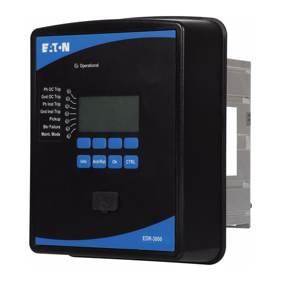
Page 158: Front Panel
EDR-3000 IM02602003E Front Panel Programmable LEDs LED »System OK« Display Protective Device Softkeys Control INFO Key RS232 Interface OK-key ACK/RST-key (Signals/Messages) Connection) PowerPort-E www.eaton.com... - Page 159 LED »System OK« Should the LED »System OK« flash red during operation, contact the Service Department immediately. Display Via the display, the User can view operational data and edit the parameters. www.eaton.com...
- Page 160 »SOFTKEYS« are contextual. On the bottom line of the display, the present function is displayed/symbolized. Possible functions are: Navigation; Parameter decrement/increment; Scrolling up/down a menu page; Moving to a digit; and Change into the parameter setting mode »Wrench Symbol«. www.eaton.com...
- Page 161 LED whose assignments are currently displayed. Via the »SOFTKEYs« »up« and »down«, the User can call up the next / previous LED. In order to leave the LED menu, press the »SOFTKEY« »left« multiple times. www.eaton.com...
- Page 162 Connection) RS232 interface. »OK Key« When using the »OK« key, parameter changes are temporarily stored. If the »OK« key is pressed again, those changes are stored indefinitely. »CTRL Key« Access to the Control menu (not available in all devices) www.eaton.com...
-
Page 163: Basic Menu Control
Fast forward scrolling is possible via »SOFTKEY« »Fast forward« Fast backward scrolling is possible via »SOFTKEY« »Fast backward« In order to return to the main menu, just keep pressing the Softkey »Arrow-Left« until you arrive at the »Main Menu». www.eaton.com... -
Page 164: Powerport-E Keyboard Commands
Reloads the displayed data of a device. Ctrl+F5 Enables the automatic refresh. Ctrl+Shift+T Moves back to the navigation window. Ctrl+F6 Walks through the tabular forms (detail windows). Page á Moves to the previous value (parameter setting). Page â Moves to the next value (parameter setting). www.eaton.com... -
Page 165: Powerport-E
Display of the device status; and Fault analysis via event and fault recorder. PowerPort-E 3.0 or higher supports reading parameter files generated by older versions of PowerPort-E. Parameter files generated by PowerPort-E 3.0 and higher cannot be read by older versions of PowerPort-E. www.eaton.com... -
Page 166: Installation Of Powerport-E
Finish the installation procedure by mouse click on the »Complete« button. If the suggested installation folder was chosen in the procedure above, the User can now call up the program via [Start > Programs > Eaton Relays> PowerPort-E]. Uninstalling PowerPort-E Via the [Start>System Control >Software] menu, the PowerPort-E application can be uninstalled from the computer. -
Page 167: Setting Up The Connection Pc - Device
Confirm the adjustments by clicking the »OK« button. If the interface is chosen for the first time, a popup window will appear “The selected connection is currently not installed. Should this connection be used for device communication? “. Confirm this by pressing the “Yes” button. www.eaton.com... - Page 168 EDR-3000 IM02602003E Parameter Setting and Evaluation via Serial/RS232 Device Example Protective Relay RS232 PowerPort-E www.eaton.com...
- Page 169 If your PC/notebook does not have an RS-232 interface, an USB-/RS232-Adapter+Null Modem Cable can be used. Only an adapter approved by Eaton Corporation may be used. First install the adapter (with the related driver that you can find on the CD) and then establish the connection (PowerPort-E =>...
- Page 170 Call up the »Device parameter/TCP/IP« menu at the HMI (panel) and set the following parameters: TCP/IP address Subnet mask Gateway Part 2: Setting the IP address within PowerPort-E Call up the menu Settings/Device Connection within PowerPort-E. Set the radio button Network Connection. Enter the IP-Address of the device that should be connected. www.eaton.com...
- Page 171 EDR-3000 IM02602003E PowerPort-E TCP/IP Device Example Parameter Setting and Evaluation via TCP/IP www.eaton.com...
- Page 172 EDR-3000 IM02602003E PowerPort-E TCP/IP Ethernet TCP/IP TCP/IP TCP/IP Protective Protective Relay Relay Device Device Device Example Example Example Parameter Setting and Evaluation via TCP/IP www.eaton.com...
- Page 173 Part 2: Setting the IP address of the gateway and the Slave ID of the device that is to be connected via Modbus tunnel using PowerPort-E Call up the menu Settings/Device Connection within PowerPort-E. Select »Modbus TCP/IP Gateway« Enter the IP-Address of the device that should be connected. Enter the Slave ID of the device. www.eaton.com...
- Page 174 EDR-3000 IM02602003E PowerPort-E TCP/IP Power Xpert Gateway IP-Address Modbus RTU Modbus RTU Modbus RTU Protective Protective Relay Relay Device Device Device Example Example Example Parameter Setting and Evaluation via Modbus Tunnel www.eaton.com...
- Page 175 Call up the menu »Internet options«. Call up the tab »Connections«. Click with the left hand mouse key on the button »Settings« on the right of the »Eaton Relays Direct Connection«. Set the check box »Use Proxy Server for this connection.
- Page 176 If a firewall is installed on your computer, TCP/IP port 52152 must have been released. If your computer does not have a serial interface, the User needs a USB-to-serial-adapter , approved by Eaton Corporation. This adapter has to be properly installed.
- Page 177 Call up the »Control Panel«. Choose »Network & Internet«. On the left side, click on »Manage Network Connections«. Right click on »Eaton Relays Direct Connection«. Choose »Delete« from the shortcut menu. Click on the »OK« button. Remove the (Virtual) Modem.
-
Page 178: Loading Of Device Data When Using Powerport-E
The »Transfer only modified parameters into the device« button only works if modified parameters are available in the PowerPort-E application. In contrast, all parameters of the device are transferred when the »Transfer all parameters into the device« button is pressed (provided all device parameters are valid). www.eaton.com... -
Page 179: Backup And Documentation When Using Powerport-E
Printing of the complete parameter tree: All values and parameters of the present parameter file are printed. Printing of the displayed working window: Only the data shown on the relevant working window are printed (i.e.: this applies, if at least one window is opened). www.eaton.com... - Page 180 If the User exports a “txt” file, the content of this file is encoded as Unicode. That means that, if the User wants to edit this file, the application must support Unicode encoded files (e.g.: Microsoft Office 2003 or higher). www.eaton.com...
-
Page 181: Off-Line Device Planning Via Powerport-E
Within the »Modify Device Configuration (Typecode)« menu, the User can modify the device configuration or simply find out the type code of the current selection. If the User wants to transfer the parameter file into a device, please refer to Section “Restoring Device Data When using PowerPort-E”. www.eaton.com... -
Page 182: Powerport-E Keyboard Commands
Load Device Data Reloads the displayed data of a device. Ctrl+F5 Enables automatic refresh. Ctrl+Shift+T Back to the navigation window. Ctrl+F6 Walks through the tabular forms (detail windows). Page á Previous value (parameter setting). Page â Next value (parameter setting). www.eaton.com... -
Page 183: Measuring Values
PowerPort-E : Per Unit quantities Primary quantities Secondary quantities Power Units (applies only for devices with power measurement) By means of the parameter » Power Units« the User can determine how measured values are to be displayed within the www.eaton.com... - Page 184 EDR-3000 IM02602003E HMI and PowerPort-E : Power Auto Scaling kW, kVAr or kVA MW, MVAr or MVA GW, GVAr or GVA www.eaton.com...
- Page 185 999,999.99 Temperature Unit (applies only for devices with temperature measurement) By means of the parameter » Temperature Unit« the User can determine how measured values are to be displayed within the HMI and PowerPort-E : ° Celsius ° Fahrenheit www.eaton.com...
-
Page 186: Current - Measured Values
Measured value (calculated): Unbalanced load current (Fundamental) [Operation /Measured Values /Current Fund.] Angle IA Measured Value (Calculated): Angle of Phasor IA [Operation /Measured Values /Current Fund.] Angle IB Measured Value (Calculated): Angle of Phasor IB [Operation /Measured Values /Current Fund.] www.eaton.com... - Page 187 IX meas RMS Measured value (measured): IX (RMS) [Operation /Measured Values /Current RMS] IR calc RMS Measured value (calculated): IR (RMS) [Operation /Measured Values /Current RMS] %IA THD Measured Value (Calculated): IA Total Harmonic Distortion [Operation /Measured Values /Current RMS] www.eaton.com...
- Page 188 Measured Value (Calculated): IB Total Harmonic Current [Operation /Measured Values /Current RMS] IC THD Measured Value (Calculated): IC Total Harmonic Current [Operation /Measured Values /Current RMS] %(I2/I1) Measured value (calculated): I2/I1, phase sequence will be taken into [Operation account automatically. /Measured Values /Current Fund.] www.eaton.com...
-
Page 189: Statistics
Where to configure? corresponding reset signal. Within menu [Device Para\ (e.g. via digital Inputs). These signals will reset Statistics\ the minimum and maximum pointers. Min/Max] Display of Minimum Values Where? Within menu [Operation\Statistics\Min] Display of Maximum Values Where? Within menu [Operation\Statistics\Max] www.eaton.com... -
Page 190: Configuration Of The Average Value Calculation
Trip (command) option to limit the average current demand: Please refert to chapter „System Alarms“ View average values and peak values Where? Within menu [Operation\Statistics\Demand] www.eaton.com... - Page 191 Trip (command) option to limit the average power demand: Yes Please refert to chapter „System Alarms“ View average values and peak values Where? Within menu [Operation\Statistics\Demand] www.eaton.com...
-
Page 192: Direct Commands
[Device Para StartFct /Statistics /Demand /Current Demand] Start I Demand Fc Start of the calculation, if the assigned signal becomes 1..n, Assignment [Device Para true. List /Statistics Only available if: Start I Demand via: = StartFct /Demand /Current Demand] www.eaton.com... - Page 193 10 min, 15 min, 30 min, 1 h, 2 h, 6 h, 12 h, 1 d, 2 d, 5 d, 7 d, 10 d, 30 d Window I Demand Window configuration Sliding, Fixed [Device Para Fixed /Statistics /Demand /Current Demand] www.eaton.com...
-
Page 194: States Of The Inputs Of The Statistics Module
/Demand /Current Demand] ResFc Max-I State of the module input: Resetting of all Maximum values [Device Para /Statistics /Min / Max] ResFc Min-I State of the module input: Resetting of all Minimum values [Device Para /Statistics /Min / Max] www.eaton.com... -
Page 195: Signals Of The Statistics Module
Number of resets since last booting. The timestamp shows date and [Operation time of the last reset. /Statistics /Min /CT] Res Cr Max values Number of resets since last booting. The timestamp shows date and [Operation time of the last reset. /Statistics /Max /CT] www.eaton.com... - Page 196 IA maximum value (RMS) [Operation /Statistics /Max /CT] IA avg RMS IA average value (RMS) [Operation /Statistics /Demand /Current Demand] IA min RMS IA minimum value (RMS) [Operation /Statistics /Min /CT] IB max RMS IB maximum value (RMS) [Operation /Statistics /Max /CT] www.eaton.com...
- Page 197 Measured value: IX minimum value (RMS) [Operation /Statistics /Min /CT] IR calc max RMS Measured value (calculated): IR maximum value (RMS) [Operation /Statistics /Max /CT] IR calc min RMS Measured value (calculated): IR minimum value (RMS) [Operation /Statistics /Min /CT] www.eaton.com...
- Page 198 IA Peak demand IA Peak value, RMS value [Operation /Statistics /Demand /Current Demand] IB Peak demand IB Peak value, RMS value [Operation /Statistics /Demand /Current Demand] IC Peak demand IC Peak value, RMS value [Operation /Statistics /Demand /Current Demand] www.eaton.com...
-
Page 199: System Alarms
The interval time (window) can be set to fixed or sliding. Example for a fixed window: If the range is set for 15 minutes, the protective device calculates the average current or power over the past 15 minutes and updates the value every 15 minutes. www.eaton.com... - Page 200 Example for a sliding window: If the sliding window is selected and the interval is set to 15 minutes, the protective device calculates and updates the average current or power continuously, for the past 15 minutes (the newest measuring value replaces the oldest measuring value continuously). www.eaton.com...
- Page 201 Average Calculation Pickup Sliding t-Delay Average Calculation Pickup Sliding t-Delay Average Calculation Pickup Window configuration = Fixed Average Calculation Average Calculation Average Calculation Average Calculation Duration Duration Duration Average Calculation Average Calculation Average Calculation Average Calculation t-Delay Average Calculation Pickup www.eaton.com...
-
Page 202: Peak Demand
In order to supervise power quality, the protective device can monitor the current THDs. Within the [System Para/System Alarms/THD] menu: Determine if an alarm is to be issued or not (Alarm active/inactive); Set the threshold; and Where applicable, set a delay time for the alarm. www.eaton.com... -
Page 203: Device Planning Parameters Of The Demand Management
If the signal becomes true, those modules/elements are blocked that are parameterized "ExBlo Fc=active". Alarm Alarm Inactive, Inactive [SysA Active /Demand /Current Demand] Threshold Threshold (to be entered as primary value) 10 - 500000A 500A [SysA /Demand /Current Demand] www.eaton.com... - Page 204 [SysA /Demand /Current Demand] Alarm Alarm Inactive, Inactive [SysA Active /THD /I THD] Threshold Threshold (to be entered as primary value) 1 - 500000A 500A [SysA /THD /I THD] t-Delay Tripping Delay 0 - 3600s [SysA /THD /I THD] www.eaton.com...
-
Page 205: States Of The Inputs Of The Demand Management
EDR-3000 IM02602003E States of the Inputs of the Demand Management Name Description Assignment via ExBlo-I Module Input State: External Blocking [SysA /General Settings] www.eaton.com... -
Page 206: Resets
Input) all ... can be menu. menu. Ex Acknowledge acknowledged. menu. *The External Acknowledgement might be disabled if parameter » Ex Acknowledgement« is set to » inactive« within menu [Device Para/Ex Acknowledge]. This blocks also the acknowledgement via Communication (e.g. Modbus). www.eaton.com... - Page 207 If the User is within the parameter setting mode, the User cannot acknowledge. In case of a fault during parameter setting via the operating panel, the User must first leave the parameter mode by pressing either the push-buttons »Ack/Rst« or »OK« before accessing the »Acknowledgements« menu via the push-button. www.eaton.com...
-
Page 208: Manual Acknowledgment
Double click on the »Operation« icon in the navigation tree. • Double click on the »Acknowledgment« icon within the operation menu. • Double click the entry within the pop-up that is to be acknowledged. • Press the »Execute immediately« button. • Enter the password. • www.eaton.com... -
Page 209: External Acknowledgments
In the working window, the User can now assign each signal that resets all acknowledgeable LEDs, a signal that • resets all Relay Outputs, a signal that resets the SCADA signals respectively, and a signal that acknowledges a pending trip command. www.eaton.com... -
Page 210: External Led - Acknowledgment Signals
Modbus.Comm Cmd 14 Communication Command Modbus.Comm Cmd 15 Communication Command Modbus.Comm Cmd 16 Communication Command Logic.LE1.Gate Out Signal: Output of the logic gate Logic.LE1.Timer Out Signal: Timer Output Logic.LE1.Out Signal: Latched Output (Q) Logic.LE1.Out inverted Signal: Negated Latched Output (Q NOT) www.eaton.com... - Page 211 Signal: Negated Latched Output (Q NOT) Logic.LE10.Gate Out Signal: Output of the logic gate Logic.LE10.Timer Out Signal: Timer Output Logic.LE10.Out Signal: Latched Output (Q) Logic.LE10.Out inverted Signal: Negated Latched Output (Q NOT) Logic.LE11.Gate Out Signal: Output of the logic gate www.eaton.com...
- Page 212 Logic.LE19.Gate Out Signal: Output of the logic gate Logic.LE19.Timer Out Signal: Timer Output Logic.LE19.Out Signal: Latched Output (Q) Logic.LE19.Out inverted Signal: Negated Latched Output (Q NOT) Logic.LE20.Gate Out Signal: Output of the logic gate Logic.LE20.Timer Out Signal: Timer Output www.eaton.com...
- Page 213 Signal: Output of the logic gate Logic.LE28.Timer Out Signal: Timer Output Logic.LE28.Out Signal: Latched Output (Q) Logic.LE28.Out inverted Signal: Negated Latched Output (Q NOT) Logic.LE29.Gate Out Signal: Output of the logic gate Logic.LE29.Timer Out Signal: Timer Output Logic.LE29.Out Signal: Latched Output (Q) www.eaton.com...
- Page 214 Logic.LE37.Out Signal: Latched Output (Q) Logic.LE37.Out inverted Signal: Negated Latched Output (Q NOT) Logic.LE38.Gate Out Signal: Output of the logic gate Logic.LE38.Timer Out Signal: Timer Output Logic.LE38.Out Signal: Latched Output (Q) Logic.LE38.Out inverted Signal: Negated Latched Output (Q NOT) www.eaton.com...
- Page 215 Signal: Negated Latched Output (Q NOT) Logic.LE47.Gate Out Signal: Output of the logic gate Logic.LE47.Timer Out Signal: Timer Output Logic.LE47.Out Signal: Latched Output (Q) Logic.LE47.Out inverted Signal: Negated Latched Output (Q NOT) Logic.LE48.Gate Out Signal: Output of the logic gate www.eaton.com...
- Page 216 Logic.LE56.Gate Out Signal: Output of the logic gate Logic.LE56.Timer Out Signal: Timer Output Logic.LE56.Out Signal: Latched Output (Q) Logic.LE56.Out inverted Signal: Negated Latched Output (Q NOT) Logic.LE57.Gate Out Signal: Output of the logic gate Logic.LE57.Timer Out Signal: Timer Output www.eaton.com...
- Page 217 Signal: Output of the logic gate Logic.LE65.Timer Out Signal: Timer Output Logic.LE65.Out Signal: Latched Output (Q) Logic.LE65.Out inverted Signal: Negated Latched Output (Q NOT) Logic.LE66.Gate Out Signal: Output of the logic gate Logic.LE66.Timer Out Signal: Timer Output Logic.LE66.Out Signal: Latched Output (Q) www.eaton.com...
- Page 218 Logic.LE74.Out Signal: Latched Output (Q) Logic.LE74.Out inverted Signal: Negated Latched Output (Q NOT) Logic.LE75.Gate Out Signal: Output of the logic gate Logic.LE75.Timer Out Signal: Timer Output Logic.LE75.Out Signal: Latched Output (Q) Logic.LE75.Out inverted Signal: Negated Latched Output (Q NOT) www.eaton.com...
- Page 219 Logic.LE79.Out Signal: Latched Output (Q) Logic.LE79.Out inverted Signal: Negated Latched Output (Q NOT) Logic.LE80.Gate Out Signal: Output of the logic gate Logic.LE80.Timer Out Signal: Timer Output Logic.LE80.Out Signal: Latched Output (Q) Logic.LE80.Out inverted Signal: Negated Latched Output (Q NOT) www.eaton.com...
-
Page 220: Manual Resets
Press the »Ack/Rst-key« during a cold start, in order to access the »Reset« menu. • Select »Reset to factory default«. • Confirm »Reset device to factory defaults and reboot« with »Yes« in order to execute the reset to factory • defaults.« www.eaton.com... -
Page 221: Status Display
To have the status display updated in a cyclic manner, select »Automatic Up- Date« in the »V « menu. State of the Module Input / Signal Is... Is Shown in PowerPort-E as... false / »0« true / »1« No connection to the device www.eaton.com... -
Page 222: Operating Panel (Hmi)
If no other key(s) is pressed at the panel, after expiration 20 - 3600s 180s [Device Para of this time, all cached (changed) parameters are /HMI] cancelled. The device access will be locked by falling back into Read-only level Lv0. www.eaton.com... -
Page 223: Recorders
In case »Auto Delete« is »Active« , the first recorded waveform will be overwritten according to the FIFO principle. If the parameter is set to »Inactive« , recording of the waveform events will be stopped until the storage location is manually released. www.eaton.com... - Page 224 EDR-3000 IM02602003E Start: 1 Trigger Start: 2 Trigger Start: 3 Trigger Start: 4 Trigger Recording Start: 5 Trigger Start: 6 Trigger Start: 7 Trigger Start: 8 Trigger Man. Trigger www.eaton.com...
- Page 225 Auto overwriting = Active Post-trigger time = 25% t-rec = Max file size Pre-trigger time = 15% Max file size = 2s Start 1 1200 ms Pre-trigger time 300 ms Post-trigger time 500 ms t-rec 2000 ms Max file size 2000 ms www.eaton.com...
- Page 226 < Max file size Auto overwriting = Active Post-trigger time = 25% Pre-trigger time = 15% Start 1 Max file size = 2s 200 ms Pre-trigger time 300 ms Post-trigger time 500 ms t-rec 1000 ms Max file size 2000 ms www.eaton.com...
- Page 227 A pop-up will appear by double clicking on a waveform record. Choose a folder where the waveform record is to be saved. The User can analyze the waveform records by means of the optionally available Quality Manager by clicking on »Yes« when asked “Shall the received waveform record be opened by the Quality Manager?" www.eaton.com...
- Page 228 Double click the »Recorders« icon in the navigation tree. Double click the »Waveform rec« icon. In the window, the waveform records are shown in tabular form. In order to delete a waveform record, double click on (the red x) in front of the waveform record and confirm. www.eaton.com...
- Page 229 /Recorders /Waveform rec] Start: 5 Start recording if the assigned signal is true. 1..n, Assignment [Device Para List /Recorders /Waveform rec] Start: 6 Start recording if the assigned signal is true. 1..n, Assignment [Device Para List /Recorders /Waveform rec] www.eaton.com...
- Page 230 /Recorders /Waveform rec] Max file size The maximum storage capacity per record is 10 seconds, 0.1 - 10.0s [Device Para including pre-trigger and post-trigger time. The waveform /Recorders recorder has a total storage capacity of 120 seconds. /Waveform rec] www.eaton.com...
- Page 231 [Device Para /Recorders /Waveform rec] Start7-I State of the module input:: Trigger event / start recording if: [Device Para /Recorders /Waveform rec] Start8-I State of the module input:: Trigger event / start recording if: [Device Para /Recorders /Waveform rec] www.eaton.com...
- Page 232 IM02602003E Waveform Recorder Module Signals Signal Description Recording Signal: Recording Memory full Signal: Memory Full Clear fail Signal: Clear Failure in Memory Res all rec Signal: All records deleted Res record Signal: Delete Record Man. Trigger Signal: Manual Trigger www.eaton.com...
- Page 233 Menu path Rec state Recording state Ready Ready, [Operation Recording, /Status display Writing file, /Recorders Trigger Blo /Waveform rec] Error code Error code [Operation Write err, /Status display Clear fail, /Recorders Calculation err, /Waveform rec] File not found, Auto overwriting www.eaton.com...
-
Page 234: Fault Recorder
A detailed fault analysis (in oscillographic form) can be done means of the Waveform Recorder. The reference between the Fault Records and the corresponding Waveform (Disturbance) Records are the » Fault Number« and the » Grid Fault Number« . www.eaton.com... - Page 235 (disjunction) of all Pickup signals. General Trip is an OR-connection of all Trips. Popup pops up on the display. Prot.Pickup Signal: General Pickup Fault duration Prot.Trip Signal: General Trip Time to trip Analog values (recording) t-meas-delay=0 t-meas-delay>0 Capture Data Capture Data www.eaton.com...
- Page 236 The last stored fault record is saved (fail-safe) within the Fault Recorder (the others are saved within a memory that depends on the auxiliary power of the protective relay). If there is no more memory free, the oldest record will be overwritten (FIFO). Up to 20 records can be stored. www.eaton.com...
- Page 237 How to find out fast, if a fault has lead to a trip or not? Faults that lead to a trip will be indicated by a flash icon (right side) within the overview menu of the fault recorder. Which fault record pops up? The newest fault. www.eaton.com...
- Page 238 In case that a direction has been detected, the evaluated direction will be displayed (this applies to directional phase and ground overcurrent relays only). Measured Values Various measuring values at the time of tripping (or delayed depending on parameter setting) will be displayed. www.eaton.com...
- Page 239 Or close the Popup by using Softkey OK Option 2 : Call up the main menu; Call up the sub-menu »Operation/Recorders/Fault rec.«; Select a fault record; and Analyze the fault record by using Softkeys Arrow Up and Arrow Down. www.eaton.com...
- Page 240 •Press the »Export to File« button. •Enter a file name. •Choose a location where to save the file. •Confirm the »Save« button. How to Test the Fault Recorder After generating an General Alarm Signal a fault record should be written. www.eaton.com...
- Page 241 Trips only [Device Para Trips only /Recorders /Fault rec] t-meas-delay After the Trip, the measurement will be delayed tor this 0 - 60ms [Device Para time. /Recorders /Fault rec] Fault Recorder Module Signals Signal Description Res record Signal: Delete Record www.eaton.com...
-
Page 242: Event Recorder
1->0 if the signal changes physically from »1« to »0«. • Counters increment is shown as: • Old Counter state -> New Counter state (e.g.: 3->4) • Alternation of multiple states are shown as: • Old state -> New state (e.g.: 0->2) • www.eaton.com... - Page 243 To have the event recorder updated in a cyclic manner, select »Automatic Up- Date« in the » View « menu . PowerPort-E is able to record more events than the device itself, if the window of the event recorder is opened and »Automatic Up-Date« is set to active. www.eaton.com...
- Page 244 •Call up the »File/Print« menu. •Choose »Print Actual Working Window« within the pop-up. •Press the »Print« button. •Press the »Export to File« button. •Enter a file name. •Choose a location where to save the file. •Confirm the »Save« button. www.eaton.com...
- Page 245 IM02602003E Direct Commands of the Event Recorder Module Parameter Description Setting range Default Menu path Res all rec Reset all records Inactive, Inactive [Operation Active /Reset] Event Recorder Module Signals Signal Description Res all rec Signal: All records deleted www.eaton.com...
-
Page 246: Trend Recorder
The Trend Recorder is to be configured within [Device Para/Recorders/Trend Recorder] menu. The User has to set the time interval. This defines the distance between two measuring points. The User can select up to ten values that will be recorded. www.eaton.com... - Page 247 CT.IB avg RMS IB average value (RMS) CT.IC avg RMS IC average value (RMS) CT.IA THD Measured Value (Calculated): IA Total Harmonic Current CT.IB THD Measured Value (Calculated): IB Total Harmonic Current CT.IC THD Measured Value (Calculated): IC Total Harmonic Current www.eaton.com...
- Page 248 1..n, TrendRecList [Device Para /Recorders /Trend rec] Observed Value7 Observed Value7 1..n, TrendRecList [Device Para /Recorders /Trend rec] Observed Value8 Observed Value8 1..n, TrendRecList [Device Para /Recorders /Trend rec] Observed Value9 Observed Value9 1..n, TrendRecList [Device Para /Recorders /Trend rec] www.eaton.com...
- Page 249 EDR-3000 IM02602003E Parameter Description Setting range Default Menu path Observed Value10 Observed Value10 1..n, TrendRecList [Device Para /Recorders /Trend rec] www.eaton.com...
- Page 250 Delete all entries Inactive, Inactive [Operation Active /Reset] Counter Values of the Trend Recorder Value Description Default Size Menu path Max avail Entries Maximum available entries in the current 0 - 9999999999 [Operation configuration /Count and RevData /Trend rec] www.eaton.com...
-
Page 251: Time Synchronization
Recommend when using Modbus RTU communication protocol and Fiber Optic when no IRIG-B real time clock is available. Modbus TCP RJ45 (Ethernet) Limited recommendation when Modbus TCP communication protocol is used and when no IRIG-B real time clock or SNTP-Server is available. www.eaton.com... -
Page 252: Accuracy Of Time Synchronization
Synchronization protocol that is used; and At Modbus TCP and SNTP: Network load and data package transmission times Please consider the accuracy of the time generator used. Deviations of the time generator's time causes the same deviations on the device's system time. www.eaton.com... - Page 253 Please carry out the following parameterization steps under [Device Para/ Time]: 5.Select your local timezone in the timezone menu. 6.There also configure the switching of daylight savings time. 7.Select » manual« as your used protocol in the TimeSync menu. 8.Set date and time. www.eaton.com...
- Page 254 March, /Timezone] April, May, June, July, August, September, October, November, December Summertime d Day of clock change summertime Sunday, Saturday [Device Para Monday, /Time Only available if: DST manual = Active Tuesday, /Timezone] Wednesday, Thursday, Friday, Saturday, General day www.eaton.com...
- Page 255 Only available if: DST manual = Active Tuesday, /Timezone] Wednesday, Thursday, Friday, Saturday, General day Wintertime w Place of selected day in month (for clock First, Last [Device Para change wintertime) Second, /Time Only available if: DST manual = Active Third, /Timezone] Fourth, Last www.eaton.com...
- Page 256 Hour of clock change wintertime 0 - 23h [Device Para /Time Only available if: DST manual = Active /Timezone] Wintertime min Minute of clock change wintertime 0 - 59min 0min [Device Para /Time Only available if: DST manual = Active /Timezone] www.eaton.com...
- Page 257 UTC+1 Berlin, UTC+0 London, UTC-1 Azores, UTC-2 Fern. d. Noronha, UTC-3 Buenos Aires, UTC-3.5 St. John’s, UTC-4 Santiago, UTC-5 New York, UTC-6 Chicago, UTC-7 Salt Lake City, UTC-8 Los Angeles, UTC-9 Anchorage, UTC-9.5 Taiohae, UTC-10 Honolulu, UTC-11 Midway Islands www.eaton.com...
- Page 258 EDR-3000 IM02602003E Parameter Description Setting range Default Menu path TimeSync Time synchronization [Device Para IRIG-B, /Time SNTP, /TimeSync Modbus /TimeSync] www.eaton.com...
-
Page 259: Sntp
GPS, radio controlled clock, or the like. If the server's “Stratum” has been set manually, it is not an indication of its quality or reliability. GPS Satellite Signal (optional ) GPS Connection (optional ) TCP/IP NTP-Server SNTP-Server NTP-Protocol TCP/IP Protective Relay (option) SNTP-Protocol www.eaton.com... - Page 260 Activate the SNTP time synchronization by means of the [Device Para/ Time/ TimeSync] menu: Select » SNTP« in the time synchronisation menu. Set the IP address of the first server in the SNTP menu. Set the IP address of the second server, if available. Set all configured servers to “active”. www.eaton.com...
- Page 261 Check if a valid IP address is set in the device (Device Para/TCP/IP). Check if the Ethernet connection is active (Device Para/TCP/IP/Link = Up?). Check if the SNTP server as well as the protection device answers to a Ping. Check if the SNTP server is up and working. www.eaton.com...
- Page 262 [Device Para Active /Time /TimeSync /SNTP] IP Byte1 IP1.IP2.IP3.IP4 0 - 255 [Device Para /Time /TimeSync /SNTP] IP Byte2 IP1.IP2.IP3.IP4 0 - 255 [Device Para /Time /TimeSync /SNTP] IP Byte3 IP1.IP2.IP3.IP4 0 - 255 [Device Para /Time /TimeSync /SNTP] www.eaton.com...
- Page 263 0 - 255 [Device Para /Time /TimeSync /SNTP] IP Byte2 IP1.IP2.IP3.IP4 0 - 255 [Device Para /Time /TimeSync /SNTP] IP Byte3 IP1.IP2.IP3.IP4 0 - 255 [Device Para /Time /TimeSync /SNTP] IP Byte4 IP1.IP2.IP3.IP4 0 - 255 [Device Para /Time /TimeSync /SNTP] www.eaton.com...
- Page 264 /Count and RevData /TimeSync /SNTP] NoOfFiltSyncs Service counter: Total Number of filtered Time 0 - 9999999999 [Operation Corrections. /Count and RevData /TimeSync /SNTP] NoOfSlowTrans Service counter: Total Number of slow Transfers. 0 0 - 9999999999 [Operation /Count and RevData /TimeSync /SNTP] www.eaton.com...
- Page 265 Precision of Server 1 [Operation 1000.00000ms /Status display /TimeSync /SNTP] PrecServer2 Precision of Server 2 [Operation 1000.00000ms /Status display /TimeSync /SNTP] ServerQlty Quality of Server used for Synchronization GOOD, [Operation (GOOD, SUFFICIENT, BAD) SUFFICENT, /Status display BAD, /TimeSync /SNTP] www.eaton.com...
- Page 266 EDR-3000 IM02602003E Value Description Default Size Menu path NetConn Quality of Network Connection (GOOD, GOOD, [Operation SUFFICIENT, BAD). SUFFICENT, /Status display BAD, /TimeSync /SNTP] www.eaton.com...
-
Page 267: Irig-B00X
GPS Satellite Signal (optional) GPS Connection (optional ) IRIG-B Time Code Generator Protective Relay Twisted Pair Cable To Other Devices The location of the IRIG-B interface depends to the device type. Please refer to the wiring diagram supplied with the protective device. www.eaton.com... - Page 268 If there is a control command assigned to an action, this action is being triggered as soon as the control command is transmitted as being true. As an example there can be triggered the start of statistics or the street lighting can be switched on through a relay. www.eaton.com...
- Page 269 Inactive [Device Para Active /Time /TimeSync /IRIG-B] IRIG-B00X Determination of the Type: IRIG-B00X. IRIG-B types IRIGB-000, IRIGB-000 [Device Para differ in types of included “Coded Expressions” (year, IRIGB-001, /Time control-functions, straight-binary-seconds). IRIGB-002, /TimeSync IRIGB-003, /IRIG-B] IRIGB-004, IRIGB-005, IRIGB-006, IRIGB-007 www.eaton.com...
- Page 270 IRIG-B00X Values Value Description Default Size Menu path NoOfFramesOK Total number valid Frames. 0 - 65535 [Operation /Count and RevData /TimeSync /IRIG-B] NoOfFrameErrors Total Number of Frame Errors. Physically 0 - 65535 [Operation corrupted Frame. /Count and RevData /TimeSync /IRIG-B] www.eaton.com...
- Page 271 EDR-3000 IM02602003E Value Description Default Size Menu path Edges Edges 0 - 65535 [Operation /Count and RevData /TimeSync /IRIG-B] www.eaton.com...
-
Page 272: Device Parameters
In order to be able to transmit a parameter file (e.g.: created off line) into the device, the following parameters must agree: Type Code (written on the top of the device/type label); and Version of the device model (can be found in the »Device Parameters\Version« menu). www.eaton.com... -
Page 273: Tcp/Ip Settings
Ethernet interface (RJ45). Contact your IT administrator in order to establish the network connection. Set the TCP/IP Parameters: Call up »Device parameter/TCP/IP« at the HMI (panel) and set the following parameters: TCP/IP address; Subnetmask; and Gateway. www.eaton.com... -
Page 274: Direct Commands Of The System Module
Only available if: Maint Mode = Activation Manually Comm, Activation via DI, Inactive, Active Program Mode Short-period bypass of the Program Mode. Inactive, Inactive [System Para Bypass Active /General Settings] CAUTION: Manually rebooting the device will release the Supervision Contact. www.eaton.com... -
Page 275: Global Protection Parameters Of The System
Parameter Setting Group Switch will be executed. In case all input functions are inactive, the device will keep working with the Setting Group that was activated lastly. Only available if: PSet-Switch = PSS via Inp fct www.eaton.com... - Page 276 DI-4P X1.DI 3 [Service Activated by Maintenance Switch /Maint Mode] Only available if: Maint Mode Activated by = Activation via DI Program Mode Program Mode Either Bkr Open or Either Bkr Open [System Para Close, or Close /General Settings] Bkr Open www.eaton.com...
-
Page 277: System Module Input States
Signal: Parameter Set Switch via Communication PSS via Inp fct Signal: Parameter Set Switch via Input Function Min. 1 param changed Signal: At least one parameter has been changed Program Mode Bypass Signal: Short-period bypass of the Program Mode. www.eaton.com... - Page 278 Signal: Reset Trip Command :HMI Ack LED-Comm Signal: LEDs Acknowledgment :Communication Ack RO-Comm Signal: Acknowledgment of the Relay Outputs :Communication Ack Counter-Comm Signal: Reset of all Counters :Communication Ack Comm-Comm Signal: Acknowledge Communication :Communication Ack TripCmd-Comm Signal: Reset Trip Command :Communication www.eaton.com...
-
Page 279: Special Values Of The System Module
EDR-3000 IM02602003E Special Values of the System Module Value Description Menu path Build Build [Device Para /Version] Version Version [Device Para /Version] Operating hours Cr Operating hours counter of the protective device [Operation /Count and RevData /Sys] www.eaton.com... -
Page 280: Communication Protocols
® To allow configuration of the devices for Modbus connection, some default values of the control system must be ® available. Device Planning Parameters of the Modbus Parameter Description Options Default Menu path Mode Mode RTU, [Device Planning] www.eaton.com... - Page 281 Baud rate error and Parity error; can be obtained from the event recorder. Error Handling – Errors on Protocol Level If, for example, an invalid memory address is inquired, error codes will be returned by the device that need to be interpreted. www.eaton.com...
- Page 282 Allow or disallow the blocking of SCADA commands. Part 3: Hardware Connection There is a RJ45 interface at the rear side of the device for the hardware connection to the control system. Establish the connection to the device by means of a proper Ethernet cable. www.eaton.com...
- Page 283 Communication System has to send a new request. Only available if:Device Planning = RTU Baud rate Baud rate 1200, 19200 [Device Para 2400, /Modbus] Only available if:Device Planning = RTU 4800, 9600, 19200, 38400 www.eaton.com...
- Page 284 Active /Modbus] because of invalid address in the requested array. The invalid addresses have a special value 0xFAFA, but the User is responsible for ignoring invalid addresses. Attention: This special value can be valid, if address is valid. www.eaton.com...
- Page 285 Comm Cmd 9 Communication Command Comm Cmd 10 Communication Command Comm Cmd 11 Communication Command Comm Cmd 12 Communication Command Comm Cmd 13 Communication Command Comm Cmd 14 Communication Command Comm Cmd 15 Communication Command Comm Cmd 16 Communication Command www.eaton.com...
- Page 286 Only available if:Device Planning = RTU /Modbus] NoOfQueryInvalid Total Number of Request errors. Request could 0 - 9999999999 [Operation not be interpreted /Count and RevData /Modbus] NoOfInternalError Total Number of Internal errors while interpreting 0 - 9999999999 [Operation the request. /Count and RevData /Modbus] www.eaton.com...
-
Page 287: Iec 61850
*.SCD file. Finally, this file has to be submitted to each device. Now the IEDs are able to communicate with each other, react to interlockings, and operate switch gear. Modbus-TCP IEC61850 Master Master Ethernet Ethernet IED1 IED2 IED3 IED1 IED2 IED3 Conventional hard wiring GOOSE IEC 61850 soft wiring www.eaton.com... - Page 288 TCP/IP settings for the IEDs • Wiring according to wiring scheme. • 2. IEC 61850 configuration (software wiring) a) Exporting an ICD file from each device b) Configuration of the substation (generating a SCD file) c) Transmit SCD file to each device. www.eaton.com...
- Page 289 Generation/Export of a Device Specific ICD File Each Eaton IEC 61850 capable device includes a description of its own functionality and communications skills in the form of an IED Capability Description (*.ICD) file. This file can be exported as follows and be used for the configuration of the substation.
- Page 290 This, in turn, may make an update of the *.SCD file necessary. IEC 61850 Virtual Outputs In addition to the standardized logical node status information, up to 16 free configurable status information items can be assigned to the 16 Virtual Outputs. This can be done in the [Device Para/IEC61850] menu. www.eaton.com...
- Page 291 EDR-3000 IM02602003E Device Planning Parameters of the IEC 61850 Parameter Description Options Default Menu path Mode Mode Do not use, [Device Planning] www.eaton.com...
- Page 292 SCD file to other devices within the IEC61850 List /IEC61850] substation. VirtualOutput6 Virtual Output. This signal can be assigned or visualized 1..n, Assignment [Device Para via the SCD file to other devices within the IEC61850 List /IEC61850] substation. www.eaton.com...
- Page 293 SCD file to other devices within the IEC61850 List /IEC61850] substation. VirtualOutput16 Virtual Output. This signal can be assigned or visualized 1..n, Assignment [Device Para via the SCD file to other devices within the IEC61850 List /IEC61850] substation. www.eaton.com...
- Page 294 SCD file to other devices within the IEC61850 List /IEC61850] substation. VirtualOutput26 Virtual Output. This signal can be assigned or visualized 1..n, Assignment [Device Para via the SCD file to other devices within the IEC61850 List /IEC61850] substation. www.eaton.com...
- Page 295 SCD file to other devices within the IEC61850 List /IEC61850] substation. VirtualOutput32 Virtual Output. This signal can be assigned or visualized 1..n, Assignment [Device Para via the SCD file to other devices within the IEC61850 List /IEC61850] substation. www.eaton.com...
- Page 296 Module input state: Binary state of the Virtual Output (GGIO) [Device Para /IEC61850] VirtOut16-I Module input state: Binary state of the Virtual Output (GGIO) [Device Para /IEC61850] VirtOut17-I Module input state: Binary state of the Virtual Output (GGIO) [Device Para /IEC61850] www.eaton.com...
- Page 297 Module input state: Binary state of the Virtual Output (GGIO) [Device Para /IEC61850] VirtOut31-I Module input state: Binary state of the Virtual Output (GGIO) [Device Para /IEC61850] VirtOut32-I Module input state: Binary state of the Virtual Output (GGIO) [Device Para /IEC61850] www.eaton.com...
- Page 298 Signal: Virtual Input (IEC61850 GGIO Ind) VirtInp28 Signal: Virtual Input (IEC61850 GGIO Ind) VirtInp29 Signal: Virtual Input (IEC61850 GGIO Ind) VirtInp30 Signal: Virtual Input (IEC61850 GGIO Ind) VirtInp31 Signal: Virtual Input (IEC61850 GGIO Ind) VirtInp32 Signal: Virtual Input (IEC61850 GGIO Ind) www.eaton.com...
- Page 299 /IEC61850] NoOfDataReadCorre Total Number of correctly read values from this 0 - 9999999999 [Operation device. /Count and RevData /IEC61850] NoOfDataWrittenAll Total Number of values written by this device 0 - 9999999999 [Operation including incorrect ones. /Count and RevData /IEC61850] www.eaton.com...
- Page 300 Total Number of correctly written values by this 0 - 9999999999 [Operation device. /Count and RevData /IEC61850] NoOfDataChangeNot Number of detected changes within the datasets 0 - 9999999999 [Operation ification that are published with GOOSE messages. /Count and RevData /IEC61850] www.eaton.com...
- Page 301 GoosePublisherState State of the GOOSE Publisher (on or off) Off, [Operation /Status display Error /IEC61850] GooseSubscriberStat State of the GOOSE Subscriber (on or off) Off, [Operation /Status display Error /IEC61850] MmsServerState State of MMS Server (on or off) Off, [Operation /Status display Error /IEC61850] www.eaton.com...
-
Page 302: Parameters
(depending on the type of device): Configure digital inputs, Assign LEDs; Configure Relay Outputs; Assign acknowledgment signals; Configure statistics; Configure general Protocol Settings; Adapt HMI settings; Configure recorders (reports); Set date and time; Change passwords; and/or Check the version (build) of the device. www.eaton.com... - Page 303 The manufacturer does not accept liability for any personal or material damage as a result of incorrect planning. Contact your Eaton Customer Service representative for more information. The protection parameters include the following protection parameter trees. Global Protection Parameters »Global Prot Para« : Here the User can find all protection parameters that are universally valid.
- Page 304 Signals represent the state of the installation/equipment (e.g.: position indicators of the breaker). Signals are assessments of the state of the grid and the equipment (System OK, Transformer failure detected, ...). Signals represent decisions that are taken by the device (e.g.: Trip Command) based on the User parameter settings. www.eaton.com...
- Page 305 EDR-3000 IM02602003E Adaptive Parameter Sets www.eaton.com...
- Page 306 Set Control logic is assigned to a logic function, the protective element will be “switched-over” to the corresponding adaptive settings if the assigned logic function is asserted and will drop-out to the “Default” setting if the assigned signal that has activated the Adaptive Set has dropped-out. www.eaton.com...
- Page 307 Logic.LE2.Out Signal: Latched Output (Q) Logic.LE2.Out inverted Signal: Negated Latched Output (Q NOT) Logic.LE3.Gate Out Signal: Output of the logic gate Logic.LE3.Timer Out Signal: Timer Output Logic.LE3.Out Signal: Latched Output (Q) Logic.LE3.Out inverted Signal: Negated Latched Output (Q NOT) www.eaton.com...
- Page 308 Signal: Negated Latched Output (Q NOT) Logic.LE12.Gate Out Signal: Output of the logic gate Logic.LE12.Timer Out Signal: Timer Output Logic.LE12.Out Signal: Latched Output (Q) Logic.LE12.Out inverted Signal: Negated Latched Output (Q NOT) Logic.LE13.Gate Out Signal: Output of the logic gate www.eaton.com...
- Page 309 Logic.LE21.Gate Out Signal: Output of the logic gate Logic.LE21.Timer Out Signal: Timer Output Logic.LE21.Out Signal: Latched Output (Q) Logic.LE21.Out inverted Signal: Negated Latched Output (Q NOT) Logic.LE22.Gate Out Signal: Output of the logic gate Logic.LE22.Timer Out Signal: Timer Output www.eaton.com...
- Page 310 Signal: Output of the logic gate Logic.LE30.Timer Out Signal: Timer Output Logic.LE30.Out Signal: Latched Output (Q) Logic.LE30.Out inverted Signal: Negated Latched Output (Q NOT) Logic.LE31.Gate Out Signal: Output of the logic gate Logic.LE31.Timer Out Signal: Timer Output Logic.LE31.Out Signal: Latched Output (Q) www.eaton.com...
- Page 311 Logic.LE39.Out Signal: Latched Output (Q) Logic.LE39.Out inverted Signal: Negated Latched Output (Q NOT) Logic.LE40.Gate Out Signal: Output of the logic gate Logic.LE40.Timer Out Signal: Timer Output Logic.LE40.Out Signal: Latched Output (Q) Logic.LE40.Out inverted Signal: Negated Latched Output (Q NOT) www.eaton.com...
- Page 312 Signal: Negated Latched Output (Q NOT) Logic.LE49.Gate Out Signal: Output of the logic gate Logic.LE49.Timer Out Signal: Timer Output Logic.LE49.Out Signal: Latched Output (Q) Logic.LE49.Out inverted Signal: Negated Latched Output (Q NOT) Logic.LE50.Gate Out Signal: Output of the logic gate www.eaton.com...
- Page 313 Logic.LE58.Gate Out Signal: Output of the logic gate Logic.LE58.Timer Out Signal: Timer Output Logic.LE58.Out Signal: Latched Output (Q) Logic.LE58.Out inverted Signal: Negated Latched Output (Q NOT) Logic.LE59.Gate Out Signal: Output of the logic gate Logic.LE59.Timer Out Signal: Timer Output www.eaton.com...
- Page 314 Signal: Output of the logic gate Logic.LE67.Timer Out Signal: Timer Output Logic.LE67.Out Signal: Latched Output (Q) Logic.LE67.Out inverted Signal: Negated Latched Output (Q NOT) Logic.LE68.Gate Out Signal: Output of the logic gate Logic.LE68.Timer Out Signal: Timer Output Logic.LE68.Out Signal: Latched Output (Q) www.eaton.com...
- Page 315 Logic.LE76.Out Signal: Latched Output (Q) Logic.LE76.Out inverted Signal: Negated Latched Output (Q NOT) Logic.LE77.Gate Out Signal: Output of the logic gate Logic.LE77.Timer Out Signal: Timer Output Logic.LE77.Out Signal: Latched Output (Q) Logic.LE77.Out inverted Signal: Negated Latched Output (Q NOT) www.eaton.com...
- Page 316 Signal: Output of the logic gate Logic.LE80.Timer Out Signal: Timer Output Logic.LE80.Out Signal: Latched Output (Q) Logic.LE80.Out inverted Signal: Negated Latched Output (Q NOT) Sys.Maint Mode Active Signal: Arc Flash Reduction Maintenance Active Sys.Maint Mode Inactive Signal: Arc Flash Reduction Maintenance Inactive www.eaton.com...
-
Page 317: Access Authorizations (Access Areas)
Breaker wear...). This password grants non-restricted Supervisor-Lv3 access to all parameters and settings of the device (device configuration). This includes also the devices planning, device parameters (e.g. Date and Time), Field Parameters, Service Parameters and Logic Parameters. www.eaton.com... - Page 318 "Read Only Lv0" a closed (locked) lock symbol will be shown in the upper right corner of the display. As soon as there are any access authorizations active (above the "Read Only-Lv0" level), the upper right corner of the display will show an unlocked (open) lock symbol. www.eaton.com...
- Page 319 Existing passwords are persistent (assined to a device). If an offline created parameter file is transmitted into a device, or if a parameter file is transmitted from one device to another, this will have no impact on existing passwords within the device. www.eaton.com...
- Page 320 Access Level for Protection Settings Access Level for Control Settings Supervisor-Lv3 Device Configuration Prot-Lv2 Control - Lv2 Protection Settings Control Settings Prot-Lv1 Control - Lv1 Reset/Ack Control Read Only-Lv0 Read Only Legend: Lv = Level Parameters are read only Parameters can be modified www.eaton.com...
-
Page 321: How To Find Out What Access Areas/Levels Are Unlocked
As soon as there is an unlocked access area (authorization) above »Read Only-Lv0« , this will be indicated by an unlocked lock symbol within the upper right corner of the device display. Unlocking Access Areas Within the menu [Device Para\Access level] access areas can be unlocked or locked (at the HMI). www.eaton.com... -
Page 322: Changing Passwords
That means, that all access areas have to be protected by a password that consists of 4 digits as minimum. The manufacturer will not overtake any liability for any personal injuries or damages that are caused by deactivated password protection. www.eaton.com... -
Page 323: Adaptive Parameters Via Hmi
4. Call up the corresponding parameter set (Adaptive Set 1 in this example). 5. Set the reduced tripping time for » AdaptSet 1« . Check and confirm that the functionality is in compliance with your protection plan via a commissioning test. www.eaton.com... - Page 324 « is detecting a manual breaker close condition, the relay switches ENABLED to Adaptive Set 1 if the signal »SOTF. « is assigned to Adaptive Set 1 . The corresponding Adaptive Set 1 will ENABLED become active and than » t = 0« sec. www.eaton.com...
- Page 325 The ground overcurrent protection can be modified by the residual voltage. This applies to devices that offer voltage protection only. Dynamic and automatic adaption of the ground current settings in order to adapt the settings to different loads (single-phase load diversity). Adaptive Parameter Sets are only available for devices with current protection modules. www.eaton.com...
-
Page 326: Access Authorizations (Access Areas)
Breaker wear...). This password grants non-restricted Supervisor-Lv3 access to all parameters and settings of the device (device configuration). This includes also the devices planning, device parameters (e.g. Date and Time), Field Parameters, Service Parameters and Logic Parameters. www.eaton.com... - Page 327 If the device was not active within the parameter setting mode for a longer time (can be set between 20 – 3600 seconds) it changes into »Read Only-Lv0« mode automatically. This parameter (t-max-Edit) can be modified within menu [Device Para\HMI]. www.eaton.com...
- Page 328 Because of that it is not possible, to acknowledge (LEDs, Output Relays...) as long as there are non saved (cached only) parameters. Acknowledgement can only be executed, when the upper right corner of the display shows this symbol: www.eaton.com...
- Page 329 Existing passwords are persistent (assined to a device). If an offline created parameter file is transmitted into a device, or if a parameter file is transmitted from one device to another, this will have no impact on existing passwords within the device. www.eaton.com...
-
Page 330: How To Find Out What Access Areas/Levels Are Unlocked
The menu [Device para\Access levels] provides the information, which access areas (authorizations) are currently unlocked. As soon as there is an unlocked access area (authorization) above »Read Only-Lv0« , this will be indicated by an unlocked lock symbol within the upper right corner of the device display. www.eaton.com... -
Page 331: Unlocking Access Areas
That means, that all access areas have to be protected by a password that consists of 4 digits as minimum. The manufacturer will not overtake any liability for any personal injuries or damages that are caused by deactivated password protection. www.eaton.com... -
Page 332: Changing Passwords Via Power-Port-E
Softkey 4 Softkey 4 Password Forgotten By pressing the »C« key during cold booting a reset menu will be called up. By selecting »Reset All Passwords?« and confirming with »Yes« all passwords will be reset to the defaults »1234« . www.eaton.com... -
Page 333: Parameter Setting At The Hmi
(star trace). This makes it possible to control or follow up from the main menu level at any time where parameter changes have been made and have not been saved finally. www.eaton.com... - Page 334 A star/parameter change indication is always overwritten by the question mark/implausibility symbol. If a device detects an implausibility, it rejects saving and adopting of the parameters. www.eaton.com...
- Page 335 Press the »OK« key to initiate the final storage of all parameter changes. Confirm the parameter changes by pressing the »Yes« Softkey or dismiss by pressing Softkey »No«. www.eaton.com...
- Page 336 A star/parameter change indication is always overwritten by the question mark/implausibility symbol. If a device detects an implausibility, it rejects saving and adopting of the parameters. www.eaton.com...
-
Page 337: Parameter Setting Via Power-Port-E
In the working window a tabulated overview appears, showing the parameters assigned to this protective function. In this table double-click the value/parameter you want to change (here: »Char« ). Another window (popup) is opened where you can select the required characteristic. www.eaton.com... - Page 338 So it is possible to see from each point of the menu tree that implausibilities have been detected by the software. A star/parameter change indication is always overwritten by the question mark/implausibility symbol. If the software detects an implausibility it rejects saving and adopting of the parameters. www.eaton.com...
- Page 339 If for more than 10 minutes no parameters are transmitted into the device, Power-Port-E will ask you again for the password, when you are trying to transmit parameters into the device. www.eaton.com...
-
Page 340: Setting Groups
(e.g. DI3 becomes active “1”, all the other assignments are inactive “0”) Via Scada Switch over if there is a clear SCADA request. Otherwise no switch over will be executed. The description of the parameters can be found within the “System Parameters” section. www.eaton.com... - Page 341 Logic.LE5.Gate Out Signal: Output of the logic gate Logic.LE5.Timer Out Signal: Timer Output Logic.LE5.Out Signal: Latched Output (Q) Logic.LE5.Out inverted Signal: Negated Latched Output (Q NOT) Logic.LE6.Gate Out Signal: Output of the logic gate Logic.LE6.Timer Out Signal: Timer Output www.eaton.com...
- Page 342 Signal: Output of the logic gate Logic.LE14.Timer Out Signal: Timer Output Logic.LE14.Out Signal: Latched Output (Q) Logic.LE14.Out inverted Signal: Negated Latched Output (Q NOT) Logic.LE15.Gate Out Signal: Output of the logic gate Logic.LE15.Timer Out Signal: Timer Output Logic.LE15.Out Signal: Latched Output (Q) www.eaton.com...
- Page 343 Logic.LE23.Out Signal: Latched Output (Q) Logic.LE23.Out inverted Signal: Negated Latched Output (Q NOT) Logic.LE24.Gate Out Signal: Output of the logic gate Logic.LE24.Timer Out Signal: Timer Output Logic.LE24.Out Signal: Latched Output (Q) Logic.LE24.Out inverted Signal: Negated Latched Output (Q NOT) www.eaton.com...
- Page 344 Signal: Negated Latched Output (Q NOT) Logic.LE33.Gate Out Signal: Output of the logic gate Logic.LE33.Timer Out Signal: Timer Output Logic.LE33.Out Signal: Latched Output (Q) Logic.LE33.Out inverted Signal: Negated Latched Output (Q NOT) Logic.LE34.Gate Out Signal: Output of the logic gate www.eaton.com...
- Page 345 Logic.LE42.Gate Out Signal: Output of the logic gate Logic.LE42.Timer Out Signal: Timer Output Logic.LE42.Out Signal: Latched Output (Q) Logic.LE42.Out inverted Signal: Negated Latched Output (Q NOT) Logic.LE43.Gate Out Signal: Output of the logic gate Logic.LE43.Timer Out Signal: Timer Output www.eaton.com...
- Page 346 Signal: Output of the logic gate Logic.LE51.Timer Out Signal: Timer Output Logic.LE51.Out Signal: Latched Output (Q) Logic.LE51.Out inverted Signal: Negated Latched Output (Q NOT) Logic.LE52.Gate Out Signal: Output of the logic gate Logic.LE52.Timer Out Signal: Timer Output Logic.LE52.Out Signal: Latched Output (Q) www.eaton.com...
- Page 347 Logic.LE60.Out Signal: Latched Output (Q) Logic.LE60.Out inverted Signal: Negated Latched Output (Q NOT) Logic.LE61.Gate Out Signal: Output of the logic gate Logic.LE61.Timer Out Signal: Timer Output Logic.LE61.Out Signal: Latched Output (Q) Logic.LE61.Out inverted Signal: Negated Latched Output (Q NOT) www.eaton.com...
- Page 348 Signal: Negated Latched Output (Q NOT) Logic.LE70.Gate Out Signal: Output of the logic gate Logic.LE70.Timer Out Signal: Timer Output Logic.LE70.Out Signal: Latched Output (Q) Logic.LE70.Out inverted Signal: Negated Latched Output (Q NOT) Logic.LE71.Gate Out Signal: Output of the logic gate www.eaton.com...
- Page 349 Logic.LE79.Gate Out Signal: Output of the logic gate Logic.LE79.Timer Out Signal: Timer Output Logic.LE79.Out Signal: Latched Output (Q) Logic.LE79.Out inverted Signal: Negated Latched Output (Q NOT) Logic.LE80.Gate Out Signal: Output of the logic gate Logic.LE80.Timer Out Signal: Timer Output www.eaton.com...
- Page 350 EDR-3000 IM02602003E Name Description Logic.LE80.Out Signal: Latched Output (Q) Logic.LE80.Out inverted Signal: Negated Latched Output (Q NOT) Sys.Maint Mode Active Signal: Arc Flash Reduction Maintenance Active Sys.Maint Mode Inactive Signal: Arc Flash Reduction Maintenance Inactive www.eaton.com...
- Page 351 Double click the »Protection Para« icon in the navigation tree. Double click the »P-Set Switch« within the protection parameters. To configure the Setting Group Switch respectively, manually choose an active set. The description of the parameters can be found within the “System Parameters” section. www.eaton.com...
- Page 352 Click on menu item »Edit« and select »Compare Parameter Sets«. Select the two parameter sets from the two drop down menus that are to be compared with each other. Press the »Compare« button. The values that are different from the set parameters will be listed in tabular form. www.eaton.com...
-
Page 353: Comparing Parameter Files Via Powerport-E
Click on »Compare with a Parameter File« within the »Device« menu. Click on the Folder icon in order to select a file on your hard disk. The differences will be shown in tabular form. www.eaton.com... -
Page 354: Converting Parameter Files Via Powerport-E
Choose the new file type from drop down menu »File Type«. Confirm the security check by clicking on »Yes« only if the User is sure that the file conversion should be executed. In tabular form the modifications will be shown as follows. Added parameter: Deleted parameter: www.eaton.com... -
Page 355: Program Mode
The program mode can be bypassed by means of the Direct Control Parameter » Program Mode Bypass« . The protective device will fall back into the program mode either: Directly after a parameter change has been saved, else 10 minutes after the bypass has been activated. www.eaton.com... -
Page 356: System Parameters
General System Parameters Parameter Description Setting range Default Menu path Phase Sequence Phase Sequence direction ABC, [System Para /General Settings] Nominal frequency 50Hz, 60Hz [System Para 60Hz /General Settings] www.eaton.com... -
Page 357: System Parameters - Current Related
"0°" or "180°". The operator has the possibility of turning the current vector by "180°" (change of sign) without modification of the wiring. This means, that – in terms of figures - the determined current indicator was turned by "180°" by the device. www.eaton.com... -
Page 358: Blocking
»Assignment list« must have been assigned. For the time the allocated blocking signal is active, the module is blocked. If the »Prot« module is blocked, the complete protection function does not work. As long as the blocking signal is active, the device cannot protect any components. www.eaton.com... - Page 359 »Active« . This gives the permission: »The tripping command of this element can be blocked«. Within the general protection parameters, an additional signal has to be chosen and assigned to the »ExBlo« parameter from the »Assignment list«. If the selected signal is activated, the temporary blockage becomes effective. www.eaton.com...
-
Page 360: To Activate Or Deactivate The Tripping Command Of A Protection Module
EDR-3000 IM02602003E To Activate or Deactivate the Tripping Command of a Protection Module www.eaton.com... -
Page 361: Activate, Deactivate Respectively To Block Temporary Protection Functions
EDR-3000 IM02602003E Activate, Deactivate Respectively to Block Temporary Protection Functions www.eaton.com... - Page 362 Current protective functions cannot only be blocked permanently (»F unction = Inactive« ) or temporarily by any blocking signal from the »Assignment list«, but also by »Reverse Interlocking« . All other protection functions can be activated, deactivated, or blocked in the same manner. www.eaton.com...
-
Page 363: Protection (Prot) Module
Choose an assignment for » ExBlo1« ; and Optionally choose an assignment for » ExBlo2« . If the signal becomes true, then all protective and supervisory functions will be blocked as long as one of these signals are true. www.eaton.com... - Page 364 EDR-3000 IM02602003E www.eaton.com...
- Page 365 If a protection element is activated and respectively decides to trip, two pickup signals will be created. The module or the protection element issues an pickup/alarm (e.g.: »50P[1].P or »50P[1].T «). ICKUP 2. The master »Prot« module collects/summarizes the signals and issues a pickup/alarm or a trip signal »P « »P «. ICKUP www.eaton.com...
- Page 366 EDR-3000 IM02602003E www.eaton.com...
- Page 367 EDR-3000 IM02602003E www.eaton.com...
- Page 368 EDR-3000 IM02602003E *=Depending on the type of device www.eaton.com...
- Page 369 EDR-3000 IM02602003E *=Depending on the type of device www.eaton.com...
-
Page 370: Direct Commands Of The Protection Module
/Prot] ExBlo2 If external blocking of this module is activated (allowed), 1..n, Assignment [Protection Para the global protection functionality of the device will be List /Global Prot Para blocked if the state of the assigned signal becomes true. /Prot] www.eaton.com... -
Page 371: Protection Module Input States
Signal: General Trip Phase B Trip Phase C Signal: General Trip Phase C Trip IX or IR Signal: General Trip Ground Fault Trip Signal: General Trip Res Fault a Mains No Signal: Resetting of fault number and number of grid faults. www.eaton.com... -
Page 372: Values Of The Protection Module
No of grid faults Number of grid faults: A grid fault, e.g. a short circuit, might cause several faults with trip and autoreclosing, each fault being identified by an increased fault number. In this case, the grid fault number remains the same. www.eaton.com... -
Page 373: Switchgear/Breaker - Manager
In case, the protective device is used for control purposes, two additional Relay Outputs have to be wired for the Control commands (issue the OPEN and CLOSE commands). That means the Relay Output for the Breaker Open and the Relay Output for the Breaker Close command. www.eaton.com... - Page 374 No switching authority (switching not allowed); Local: Switching only via push buttons at the panel; Remote: Switching only via SCADA, digital inputs, or internal signals; and Local and Remote: Switching via push buttons, SCADA, digital inputs, or internal signals. www.eaton.com...
-
Page 375: Single Line Diagram
The configuration file includes the single line diagram and the switchgear properties. Switchgear properties and single line diagram are coupled via the configuration file. The default settings of the switchgears depend on the used Single Line. The shown default values correspond to a Single Line with two circuit breakers and to isolating switches. www.eaton.com... - Page 376 « State will become true. If the command is executed and the breaker has reached the end position before the NDETERM timer has elapsed, »P OPEN« will become true. Otherwise, if the timer has elapsed »P « will become true. ISTURB www.eaton.com...
- Page 377 (while a Moving Intermediate timer is running) timer is running) (while a Moving (while a Moving Intermediate timer is running) timer is running) OPEN CLOSE Disturbed (Moving timer (Moving timer elapsed) elapsed) (Moving timer (Moving timer Disturbed elapsed) elapsed) www.eaton.com...
- Page 378 Pos CLOSE Pos OPEN Pos Indeterm Pos Disturb Breaker State Not wired (while t-Move (while t-Move Intermediate CLOSE is CLOSE is running) running) Not wired Not wired Not wired Disturbed (after t-Move (after t-Move CLOSE is CLOSE is elapsed) elapsed) www.eaton.com...
- Page 379 Pos CLOSE Pos OPEN Pos Indeterm Pos Disturb Breaker State Not wired (while t-Move (while t-Move Intermediate OPEN is OPEN is running) running) Not wired Not wired Not wired (after t-Move (after t-Move Disturbed OPEN is OPEN is elapsed) elapsed) www.eaton.com...
- Page 380 Signal: Trip Command 51R[1].TripCmd Signal: Trip Command 51R[2].TripCmd Signal: Trip Command 46[1].TripCmd Signal: Trip Command 46[2].TripCmd Signal: Trip Command ZI.TripCmd Signal: Zone Interlocking Trip Command ExP[1].TripCmd Signal: Trip Command ExP[2].TripCmd Signal: Trip Command ExP[3].TripCmd Signal: Trip Command ExP[4].TripCmd Signal: Trip Command www.eaton.com...
- Page 381 Signal Breaker Ready Protection Trip Command Trigger [x] Trigger [x] Position Indication: OPEN, CLOSE, Trigger [x] Indeterminated, Disturbed Trip Command 50P[x] SCADA Trip Command 51P[x] Autoreclosure CLOSE Trip Command XX[x] Trip Command 27[x] Trip Command 59[x] Trip Command XX[x] www.eaton.com...
- Page 382 EDR-3000 IM02602003E www.eaton.com...
- Page 383 Please note: The Protection Trip commands and the reclosure command of the auto reclosure module will be issued without interlocking. In cases when the breaker must not be opened, the protection trip command has to be inhibited by a separate blocking signal. www.eaton.com...
- Page 384 EDR-3000 IM02602003E Trip command Interlockings assigned and configured within the Trip manager www.eaton.com...
- Page 385 If a signal is assigned to the » Synchronism« input, the closing of the switchgear will be performed only when this signal gets active during the maximum allowed waiting time » t-MaxSyncSuperv« . If no signal is assigned to the » Synchronism« input, the synchronism release is permanently. www.eaton.com...
- Page 386 EDR-3000 IM02602003E Direct Commands of the Switchgear/Breaker Parameter Description Setting range Default Menu path Res Bwear Sl Resetting the slow breaker alarm Inactive, Inactive [Operation Breaker Active /Reset] Ack TripCmd Acknowledge Trip Command Inactive, Inactive [Operation Active /Reset] www.eaton.com...
- Page 387 /Interlockings] Interl OPEN3 Interlocking of the OPEN command 1..n, Assignment [Control List /Bkr /Interlockings] SC CLOSE Switching CLOSE Command, e.g. the state of the Logics 1..n, DI-LogicList [Control or the state of the digital input /Bkr /Ex OPEN/CLOSE Cmd] www.eaton.com...
- Page 388 Open Command to the Breaker if the state of the 1..n, Trip Cmds 51X[1].TripCmd [Control assigned signal becomes true. /Bkr /Trip Manager] Trigger7 Open Command to the Breaker if the state of the 1..n, Trip Cmds 50R[1].TripCmd [Control assigned signal becomes true. /Bkr /Trip Manager] www.eaton.com...
- Page 389 Open Command to the Breaker if the state of the 1..n, Trip Cmds [Control assigned signal becomes true. /Bkr /Trip Manager] Trigger18 Open Command to the Breaker if the state of the 1..n, Trip Cmds [Control assigned signal becomes true. /Bkr /Trip Manager] www.eaton.com...
- Page 390 GENERATOR2SYSTEM working mode. /Synchron Switchg] t-Move CLOSE Time to move to the CLOSE Position 0.01 - 100.00s 0.1s [Control /Bkr /General Settings] t-Move OPEN Time to move to the OPEN Position 0.01 - 100.00s 0.1s [Control /Bkr /General Settings] www.eaton.com...
- Page 391 State of the module input: Interlocking of the OPEN command [Control /Bkr /Interlockings] Interl OPEN2-I State of the module input: Interlocking of the OPEN command [Control /Bkr /Interlockings] Interl OPEN3-I State of the module input: Interlocking of the OPEN command [Control /Bkr /Interlockings] www.eaton.com...
- Page 392 CES SyncTimeout Signal: Command Execution Supervision: Switching Command not executed. No Synchronization signal while t-sync was running. CES SG removed Signal: Command Execution Supervision: Switching Command unsuccessful, Switchgear removed. Prot CLOSE Signal: CLOSE command issued by the Prot module www.eaton.com...
- Page 393 Signal: OPEN command issued to the switchgear. Depending on the setting the signal may include the OPEN command of the Prot module. CLOSE Cmd manual Signal: CLOSE Cmd manual OPEN Cmd manual Signal: OPEN Cmd manual Sync CLOSE request Signal: Synchronous CLOSE request www.eaton.com...
-
Page 394: Switching The Breaker At The Panel
4. A symbol for the switchgear and its status (ON, OFF, intermediate or disturbed) is displayed. 5. Dependent on the status (ON/OFF), the switchgear can be switched ON or OFF by the corresponding softkey. The current position of the switchgear will be visualized by different symbols: Breaker State Symbol (Intermediate) (OFF) (ON) (Disturbed) www.eaton.com... - Page 395 Command Execution Supervision: Switching Command not executed. No switching authority. CES DoubleOperating Command Execution Supervision: A second switch command is in conflict with a pending one. No. of rej. Com No. of rej. Com because Locked by ParaSystem The following Signals can trigger the Sync-check: www.eaton.com...
-
Page 396: Breaker Wear
An increase of the closing or opening time of the breaker is an indication for the maintenance need of this switchgear. If the measured time exceeds the time » t-Move OPEN« or » t-Move CLOSE«, the signal »B « will be WEAR REAKER activated. This signal will be active until it is reset manually. www.eaton.com... - Page 397 When the interrupted current is greater than the interrupt current at the last point, the protective relay will assume zero operation counts. Breaker Maintenance Curve for a typical 25kV Breaker 1 10 × 10000 10000 1 10 × 20.0 20.0 Interrupted Current in kA per operation www.eaton.com...
- Page 398 /Bwear] Count1 Open Counts Allowed #1 1 - 32000 10000 [Control /Bkr Only available if:Bwear Curve Fc = Active /Bwear] Current2 Interrupted Current Level #2 0.00 - 2000.00kA 1.00kA [Control /Bkr Only available if:Bwear Curve Fc = Active /Bwear] www.eaton.com...
- Page 399 Only available if:Bwear Curve Fc = Active /Bwear] Current7 Interrupted Current Level #7 0.00 - 2000.00kA 13.00kA [Control /Bkr Only available if:Bwear Curve Fc = Active /Bwear] Count7 Open Counts Allowed #7 1 - 32000 [Control /Bkr Only available if:Bwear Curve Fc = Active /Bwear] www.eaton.com...
- Page 400 Only available if:Bwear Curve Fc = Active /Bwear] Current10 Interrupted Current Level #10 0.00 - 2000.00kA 25.00kA [Control /Bkr Only available if:Bwear Curve Fc = Active /Bwear] Count10 Open Counts Allowed #10 1 - 32000 [Control /Bkr Only available if:Bwear Curve Fc = Active /Bwear] www.eaton.com...
- Page 401 Signal: Reset of the Breaker Wear maintenance curve. Isum Intr ph Alm Signal: Alarm, the per hour Sum (Limit) of interrupting currents has been exceeded. Res Isum Intr ph Alm Signal: Reset of the Alarm, "the per hour Sum (Limit) of interrupting currents has been exceeded". www.eaton.com...
- Page 402 Sum per hour of interrupting currents. 0.00kA 0.00 - 1000.00kA [Operation /Count and RevData /Control /Bkr] Bkr OPEN capacity CB OPEN capacity. 100% means, that the 0.0% 0.0 - 100.0% [Operation breaker is to be maintenanced. /Count and RevData /Control /Bkr] www.eaton.com...
- Page 403 Signal: Digital Input DI-4P X1.DI 4 Signal: Digital Input DI-8P X1.DI 1 Signal: Digital Input DI-8P X1.DI 2 Signal: Digital Input DI-8P X1.DI 3 Signal: Digital Input DI-8P X1.DI 4 Signal: Digital Input DI-8P X1.DI 5 Signal: Digital Input www.eaton.com...
- Page 404 Logic.LE8.Gate Out Signal: Output of the logic gate Logic.LE8.Timer Out Signal: Timer Output Logic.LE8.Out Signal: Latched Output (Q) Logic.LE8.Out inverted Signal: Negated Latched Output (Q NOT) Logic.LE9.Gate Out Signal: Output of the logic gate Logic.LE9.Timer Out Signal: Timer Output www.eaton.com...
- Page 405 Signal: Output of the logic gate Logic.LE17.Timer Out Signal: Timer Output Logic.LE17.Out Signal: Latched Output (Q) Logic.LE17.Out inverted Signal: Negated Latched Output (Q NOT) Logic.LE18.Gate Out Signal: Output of the logic gate Logic.LE18.Timer Out Signal: Timer Output Logic.LE18.Out Signal: Latched Output (Q) www.eaton.com...
- Page 406 Logic.LE26.Out Signal: Latched Output (Q) Logic.LE26.Out inverted Signal: Negated Latched Output (Q NOT) Logic.LE27.Gate Out Signal: Output of the logic gate Logic.LE27.Timer Out Signal: Timer Output Logic.LE27.Out Signal: Latched Output (Q) Logic.LE27.Out inverted Signal: Negated Latched Output (Q NOT) www.eaton.com...
- Page 407 Signal: Negated Latched Output (Q NOT) Logic.LE36.Gate Out Signal: Output of the logic gate Logic.LE36.Timer Out Signal: Timer Output Logic.LE36.Out Signal: Latched Output (Q) Logic.LE36.Out inverted Signal: Negated Latched Output (Q NOT) Logic.LE37.Gate Out Signal: Output of the logic gate www.eaton.com...
- Page 408 Logic.LE45.Gate Out Signal: Output of the logic gate Logic.LE45.Timer Out Signal: Timer Output Logic.LE45.Out Signal: Latched Output (Q) Logic.LE45.Out inverted Signal: Negated Latched Output (Q NOT) Logic.LE46.Gate Out Signal: Output of the logic gate Logic.LE46.Timer Out Signal: Timer Output www.eaton.com...
- Page 409 Signal: Output of the logic gate Logic.LE54.Timer Out Signal: Timer Output Logic.LE54.Out Signal: Latched Output (Q) Logic.LE54.Out inverted Signal: Negated Latched Output (Q NOT) Logic.LE55.Gate Out Signal: Output of the logic gate Logic.LE55.Timer Out Signal: Timer Output Logic.LE55.Out Signal: Latched Output (Q) www.eaton.com...
- Page 410 Logic.LE63.Out Signal: Latched Output (Q) Logic.LE63.Out inverted Signal: Negated Latched Output (Q NOT) Logic.LE64.Gate Out Signal: Output of the logic gate Logic.LE64.Timer Out Signal: Timer Output Logic.LE64.Out Signal: Latched Output (Q) Logic.LE64.Out inverted Signal: Negated Latched Output (Q NOT) www.eaton.com...
- Page 411 Signal: Negated Latched Output (Q NOT) Logic.LE73.Gate Out Signal: Output of the logic gate Logic.LE73.Timer Out Signal: Timer Output Logic.LE73.Out Signal: Latched Output (Q) Logic.LE73.Out inverted Signal: Negated Latched Output (Q NOT) Logic.LE74.Gate Out Signal: Output of the logic gate www.eaton.com...
- Page 412 Logic.LE79.Out Signal: Latched Output (Q) Logic.LE79.Out inverted Signal: Negated Latched Output (Q NOT) Logic.LE80.Gate Out Signal: Output of the logic gate Logic.LE80.Timer Out Signal: Timer Output Logic.LE80.Out Signal: Latched Output (Q) Logic.LE80.Out inverted Signal: Negated Latched Output (Q NOT) www.eaton.com...
-
Page 413: Control - Example: Switching Of A Breaker
»Local«. If no switching authority is given, this has to be set first to »Local« or »Local and Remote«. With the softkey »OK« it can be switched back to the single line diagram page. www.eaton.com... - Page 414 Push the »right arrow« softkey to get to the control page. The breaker is opened, therefore it can be closed only. After pushing the softkey »CLOSE« a confirmation window appears. When you are sure to proceed with the switching operation, press the softkey »YES«. www.eaton.com...
- Page 415 It will be shown on the display when the switchgear reaches the new end position. Further possible switching operations (OPEN) will be displayed by softkeys. Notice: For the case, the switchgear does not reach the new end position within the set supervision time the following Warning appears on the display. www.eaton.com...
-
Page 416: Protective Elements
Pickup = If the pickup value is exceeded, the module /element starts to time out to trip . This element offers a criterion setting. The criterion setting tells if the threshold is based on the fundamental (Phasor) or RMS. For Tripping curves, please refer to the “Appendix/Instantaneous Current Curves (Phase)” section. www.eaton.com... - Page 417 EDR-3000 IM02602003E *=Applies only to devices that offer Inrush Protection www.eaton.com...
- Page 418 (allowed) within a parameter set and if the state of the List /Global Prot Para assigned signal is true. /I-Prot /50P[1]] AdaptSet 1 Assignment Adaptive Parameter 1 AdaptSet [Protection Para /Global Prot Para /I-Prot /50P[1]] AdaptSet 2 Assignment Adaptive Parameter 2 AdaptSet [Protection Para /Global Prot Para /I-Prot /50P[1]] www.eaton.com...
- Page 419 EDR-3000 IM02602003E Parameter Description Setting range Default Menu path AdaptSet 3 Assignment Adaptive Parameter 3 AdaptSet [Protection Para /Global Prot Para /I-Prot /50P[1]] AdaptSet 4 Assignment Adaptive Parameter 4 AdaptSet [Protection Para /Global Prot Para /I-Prot /50P[1]] www.eaton.com...
- Page 420 50P[2]: 2.5In /<1..4> Only available if: Characteristic = DEFT Or Characteristic 50P[3]: 3.0In /I-Prot = INV Minimum of the setting range If: VRestraint = /50P[1]] Active Minimum of the setting range If: VRestraint = Inactive www.eaton.com...
- Page 421 EDR-3000 IM02602003E Parameter Description Setting range Default Menu path Tripping delay 0.00 - 300.00s 50P[1]: 0s [Protection Para 50P[2]: 0.25s /<1..4> Only available if: Characteristic = DEFT 50P[3]: 0.25s /I-Prot /50P[1]] www.eaton.com...
- Page 422 AdaptSet2-I Module Input State: Adaptive Parameter2 [Protection Para /Global Prot Para /I-Prot /50P[1]] AdaptSet3-I Module Input State: Adaptive Parameter3 [Protection Para /Global Prot Para /I-Prot /50P[1]] AdaptSet4-I Module Input State: Adaptive Parameter4 [Protection Para /Global Prot Para /I-Prot /50P[1]] www.eaton.com...
- Page 423 Signal: Trip TripCmd Signal: Trip Command Active AdaptSet Active Adaptive Parameter DefaultSet Signal: Default Parameter Set AdaptSet 1 Signal: Adaptive Parameter 1 AdaptSet 2 Signal: Adaptive Parameter 2 AdaptSet 3 Signal: Adaptive Parameter 3 AdaptSet 4 Signal: Adaptive Parameter 4 www.eaton.com...
- Page 424 3 x single-phase and 1 x three-phase. Eaton recommends measuring the total tripping time instead of the tripping delay. The tripping delay should be specified by the User. The total tripping time is measured at the position signaling contact of the breaker (not at the relay output contacts!).
-
Page 425: 51P - Inv Overcurrent-Protection
EINV (IEC/XInv); • MINV (ANSI/XInv); • VINV (ANSI/XInv); • EINV (ANSI/XInv); • Thermal Flat; • Therm Flat IT; • Therm Flat I2T; and • Therm Flat I4T. • For tripping curves please refer to the “Appendix/Time Current Curves (PHASE)” section. www.eaton.com... - Page 426 EDR-3000 IM02602003E *=Applies only to devices that offer Inrush Protection www.eaton.com...
- Page 427 (allowed) within a parameter set and if the state of the List /Global Prot Para assigned signal is true. /I-Prot /51P[1]] AdaptSet 1 Assignment Adaptive Parameter 1 AdaptSet [Protection Para /Global Prot Para /I-Prot /51P[1]] AdaptSet 2 Assignment Adaptive Parameter 2 AdaptSet [Protection Para /Global Prot Para /I-Prot /51P[1]] www.eaton.com...
- Page 428 EDR-3000 IM02602003E Parameter Description Setting range Default Menu path AdaptSet 3 Assignment Adaptive Parameter 3 AdaptSet [Protection Para /Global Prot Para /I-Prot /51P[1]] AdaptSet 4 Assignment Adaptive Parameter 4 AdaptSet [Protection Para /Global Prot Para /I-Prot /51P[1]] www.eaton.com...
- Page 429 If the pickup value is exceeded, the module/element 0.02 - 40.00In 1.00In [Protection Para starts to time out to trip. /<1..4> Minimum of the setting range If: VRestraint = Active /I-Prot Minimum of the setting range If: VRestraint = Inactive /51P[1]] www.eaton.com...
- Page 430 51P[3]: 3 /I-Prot /51P[1]] Reset Mode Reset Mode Instantaneous, Calculated [Protection Para t-delay, /<1..4> Calculated /I-Prot /51P[1]] t-reset Reset time for intermittent phase failures (INV 0.00 - 60.00s [Protection Para characteristics only) /<1..4> Available if:Reset Mode = t-delay /I-Prot /51P[1]] www.eaton.com...
- Page 431 AdaptSet2-I Module Input State: Adaptive Parameter2 [Protection Para /Global Prot Para /I-Prot /51P[1]] AdaptSet3-I Module Input State: Adaptive Parameter3 [Protection Para /Global Prot Para /I-Prot /51P[1]] AdaptSet4-I Module Input State: Adaptive Parameter4 [Protection Para /Global Prot Para /I-Prot /51P[1]] www.eaton.com...
- Page 432 Signal: Trip TripCmd Signal: Trip Command Active AdaptSet Active Adaptive Parameter DefaultSet Signal: Default Parameter Set AdaptSet 1 Signal: Adaptive Parameter 1 AdaptSet 2 Signal: Adaptive Parameter 2 AdaptSet 3 Signal: Adaptive Parameter 3 AdaptSet 4 Signal: Adaptive Parameter 4 www.eaton.com...
- Page 433 (recommended), or alternatively tripping delays and the drop-out ratios; each time 3 x single-phase and 1 x three-phase. Eaton recommends measuring the total tripping time instead of the tripping delay. The tripping delay should be specified by the User. The total tripping time is measured at the position signaling contact of the breaker (not at the relay output contacts!).
-
Page 434: 50X Deft Measured Ground Fault Protection
The ground current can be measured either directly via a zero sequence transformer or detected by a residual connection. The ground current can alternatively be calculated from the phase currents. However, this is only possible if the current transformers are Wye-connected. www.eaton.com... - Page 435 EDR-3000 IM02602003E *=Applies only to devices that offer Inrush Protection www.eaton.com...
- Page 436 (allowed) within a parameter set and if the state of the List /Global Prot Para assigned signal is true. /I-Prot /50X[1]] AdaptSet 1 Assignment Adaptive Parameter 1 AdaptSet [Protection Para /Global Prot Para /I-Prot /50X[1]] AdaptSet 2 Assignment Adaptive Parameter 2 AdaptSet [Protection Para /Global Prot Para /I-Prot /50X[1]] www.eaton.com...
- Page 437 EDR-3000 IM02602003E Parameter Description Setting range Default Menu path AdaptSet 3 Assignment Adaptive Parameter 3 AdaptSet [Protection Para /Global Prot Para /I-Prot /50X[1]] AdaptSet 4 Assignment Adaptive Parameter 4 AdaptSet [Protection Para /Global Prot Para /I-Prot /50X[1]] www.eaton.com...
- Page 438 Measuring method: fundamental or rms or 3rd harmonic Fundamental, True RMS [Protection Para (only generator protection relays) True RMS /<1..4> /I-Prot /50X[1]] Pickup If the pickup value is exceeded, the module/element will 0.02 - 20.00In 50X[1]: 1In [Protection Para be started. 50X[2]: 2In /<1..4> /I-Prot /50X[1]] www.eaton.com...
- Page 439 Pickup (sensitive) If the pickup value is exceeded, the module/element will 0.002 - 2.000In 0.02In [Protection Para be started. /<1..4> /I-Prot /50X[1]] Tripping delay 0.00 - 300.00s 0.5s [Protection Para /<1..4> Only available if: Characteristic = DEFT /I-Prot /50X[1]] www.eaton.com...
- Page 440 AdaptSet2-I Module Input State: Adaptive Parameter2 [Protection Para /Global Prot Para /I-Prot /50X[1]] AdaptSet3-I Module Input State: Adaptive Parameter3 [Protection Para /Global Prot Para /I-Prot /50X[1]] AdaptSet4-I Module Input State: Adaptive Parameter4 [Protection Para /Global Prot Para /I-Prot /50X[1]] www.eaton.com...
- Page 441 Signal: Trip TripCmd Signal: Trip Command Active AdaptSet Active Adaptive Parameter DefaultSet Signal: Default Parameter Set AdaptSet 1 Signal: Adaptive Parameter 1 AdaptSet 2 Signal: Adaptive Parameter 2 AdaptSet 3 Signal: Adaptive Parameter 3 AdaptSet 4 Signal: Adaptive Parameter 4 www.eaton.com...
- Page 442 EDR-3000 IM02602003E Commissioning: Ground Fault Protection – Non-directional [ANSI 50X] Please test the non-directional ground overcurrent analog to the non-directional phase overcurrent protection. www.eaton.com...
-
Page 443: 51X Inv Measured Ground Fault Protection
The ground current can be measured either directly via a zero sequence transformer or detected by a residual connection. The ground current can alternatively be calculated from the phase currents. However, this is only possible if the current transformers are Wye-connected. www.eaton.com... - Page 444 EDR-3000 IM02602003E *=Applies only to devices that offer Inrush Protection www.eaton.com...
- Page 445 (allowed) within a parameter set and if the state of the List /Global Prot Para assigned signal is true. /I-Prot /51X[1]] AdaptSet 1 Assignment Adaptive Parameter 1 AdaptSet [Protection Para /Global Prot Para /I-Prot /51X[1]] AdaptSet 2 Assignment Adaptive Parameter 2 AdaptSet [Protection Para /Global Prot Para /I-Prot /51X[1]] www.eaton.com...
- Page 446 EDR-3000 IM02602003E Parameter Description Setting range Default Menu path AdaptSet 3 Assignment Adaptive Parameter 3 AdaptSet [Protection Para /Global Prot Para /I-Prot /51X[1]] AdaptSet 4 Assignment Adaptive Parameter 4 AdaptSet [Protection Para /Global Prot Para /I-Prot /51X[1]] www.eaton.com...
- Page 447 Measuring method: fundamental or rms or 3rd harmonic Fundamental, True RMS [Protection Para (only generator protection relays) True RMS /<1..4> /I-Prot /51X[1]] Pickup If the pickup value is exceeded, the module/element will 0.02 - 20.00In 0.5In [Protection Para be started. /<1..4> /I-Prot /51X[1]] www.eaton.com...
- Page 448 /51X[1]] Reset Mode Reset Mode Instantaneous, Calculated [Protection Para t-delay, /<1..4> Calculated /I-Prot /51X[1]] t-reset Reset time for intermittent phase failures (INV 0.00 - 60.00s 0.00s [Protection Para characteristics only) /<1..4> Only available if:Reset Mode = t-delay /I-Prot /51X[1]] www.eaton.com...
- Page 449 AdaptSet2-I Module Input State: Adaptive Parameter2 [Protection Para /Global Prot Para /I-Prot /51X[1]] AdaptSet3-I Module Input State: Adaptive Parameter3 [Protection Para /Global Prot Para /I-Prot /51X[1]] AdaptSet4-I Module Input State: Adaptive Parameter4 [Protection Para /Global Prot Para /I-Prot /51X[1]] www.eaton.com...
- Page 450 Signal: Trip TripCmd Signal: Trip Command Active AdaptSet Active Adaptive Parameter DefaultSet Signal: Default Parameter Set AdaptSet 1 Signal: Adaptive Parameter 1 AdaptSet 2 Signal: Adaptive Parameter 2 AdaptSet 3 Signal: Adaptive Parameter 3 AdaptSet 4 Signal: Adaptive Parameter 4 www.eaton.com...
- Page 451 EDR-3000 IM02602003E Commissioning: Ground Fault Protection – Non-directional [ANSI 51X] Please test the non-directional ground overcurrent analog to the non-directional phase overcurrent protection. www.eaton.com...
-
Page 452: 50R Deft Calculated Ground Fault Protection Module
The ground current can be measured either directly via a zero sequence transformer or detected by a residual connection. The ground current can alternatively be calculated from the phase currents. However, this is only possible if the current transformers are Wye-connected. www.eaton.com... - Page 453 EDR-3000 IM02602003E *=Applies only to devices that offer Inrush Protection www.eaton.com...
- Page 454 (allowed) within a parameter set and if the state of the List /Global Prot Para assigned signal is true. /I-Prot /50R[1]] AdaptSet 1 Assignment Adaptive Parameter 1 AdaptSet [Protection Para /Global Prot Para /I-Prot /50R[1]] AdaptSet 2 Assignment Adaptive Parameter 2 AdaptSet [Protection Para /Global Prot Para /I-Prot /50R[1]] www.eaton.com...
- Page 455 EDR-3000 IM02602003E Parameter Description Setting range Default Menu path AdaptSet 3 Assignment Adaptive Parameter 3 AdaptSet [Protection Para /Global Prot Para /I-Prot /50R[1]] AdaptSet 4 Assignment Adaptive Parameter 4 AdaptSet [Protection Para /Global Prot Para /I-Prot /50R[1]] www.eaton.com...
- Page 456 Measuring method: fundamental or rms or 3rd harmonic Fundamental, True RMS [Protection Para (only generator protection relays) True RMS /<1..4> /I-Prot /50R[1]] Pickup If the pickup value is exceeded, the module/element will 0.02 - 20.00In 50R[1]: 1In [Protection Para be started. 50R[2]: 2In /<1..4> /I-Prot /50R[1]] www.eaton.com...
- Page 457 EDR-3000 IM02602003E Parameter Description Setting range Default Menu path Tripping delay 0.00 - 300.00s 0.5s [Protection Para /<1..4> Only available if: Characteristic = DEFT /I-Prot /50R[1]] www.eaton.com...
- Page 458 AdaptSet2-I Module Input State: Adaptive Parameter2 [Protection Para /Global Prot Para /I-Prot /50R[1]] AdaptSet3-I Module Input State: Adaptive Parameter3 [Protection Para /Global Prot Para /I-Prot /50R[1]] AdaptSet4-I Module Input State: Adaptive Parameter4 [Protection Para /Global Prot Para /I-Prot /50R[1]] www.eaton.com...
- Page 459 Signal: Trip TripCmd Signal: Trip Command Active AdaptSet Active Adaptive Parameter DefaultSet Signal: Default Parameter Set AdaptSet 1 Signal: Adaptive Parameter 1 AdaptSet 2 Signal: Adaptive Parameter 2 AdaptSet 3 Signal: Adaptive Parameter 3 AdaptSet 4 Signal: Adaptive Parameter 4 www.eaton.com...
- Page 460 EDR-3000 IM02602003E Commissioning: Ground Fault Protection – Non-directional [ANSI 50R] Please test the non-directional ground overcurrent using the procedure for non-directional phase overcurrent protection. www.eaton.com...
-
Page 461: 51R Inv Calculated Ground Fault Protection
The ground current can be measured either directly via a zero sequence transformer or detected by a residual connection. The ground current can alternatively be calculated from the phase currents. However, this is only possible if the current transformers are Wye-connected. www.eaton.com... - Page 462 EDR-3000 IM02602003E *=Applies only to devices that offer Inrush Protection www.eaton.com...
- Page 463 (allowed) within a parameter set and if the state of the List /Global Prot Para assigned signal is true. /I-Prot /51R[1]] AdaptSet 1 Assignment Adaptive Parameter 1 AdaptSet [Protection Para /Global Prot Para /I-Prot /51R[1]] AdaptSet 2 Assignment Adaptive Parameter 2 AdaptSet [Protection Para /Global Prot Para /I-Prot /51R[1]] www.eaton.com...
- Page 464 EDR-3000 IM02602003E Parameter Description Setting range Default Menu path AdaptSet 3 Assignment Adaptive Parameter 3 AdaptSet [Protection Para /Global Prot Para /I-Prot /51R[1]] AdaptSet 4 Assignment Adaptive Parameter 4 AdaptSet [Protection Para /Global Prot Para /I-Prot /51R[1]] www.eaton.com...
- Page 465 Measuring method: fundamental or rms or 3rd harmonic Fundamental, True RMS [Protection Para (only generator protection relays) True RMS /<1..4> /I-Prot /51R[1]] Pickup If the pickup value is exceeded, the module/element will 0.02 - 20.00In 51R[1]: 0.1In [Protection Para be started. 51R[2]: 0.5In /<1..4> /I-Prot /51R[1]] www.eaton.com...
- Page 466 /51R[1]] Reset Mode Reset Mode Instantaneous, Calculated [Protection Para t-delay, /<1..4> Calculated /I-Prot /51R[1]] t-reset Reset time for intermittent phase failures (INV 0.00 - 60.00s 0.00s [Protection Para characteristics only) /<1..4> Only available if:Reset Mode = t-delay /I-Prot /51R[1]] www.eaton.com...
- Page 467 AdaptSet2-I Module Input State: Adaptive Parameter2 [Protection Para /Global Prot Para /I-Prot /51R[1]] AdaptSet3-I Module Input State: Adaptive Parameter3 [Protection Para /Global Prot Para /I-Prot /51R[1]] AdaptSet4-I Module Input State: Adaptive Parameter4 [Protection Para /Global Prot Para /I-Prot /51R[1]] www.eaton.com...
- Page 468 Signal: Trip TripCmd Signal: Trip Command Active AdaptSet Active Adaptive Parameter DefaultSet Signal: Default Parameter Set AdaptSet 1 Signal: Adaptive Parameter 1 AdaptSet 2 Signal: Adaptive Parameter 2 AdaptSet 3 Signal: Adaptive Parameter 3 AdaptSet 4 Signal: Adaptive Parameter 4 www.eaton.com...
- Page 469 EDR-3000 IM02602003E Commissioning: Ground Fault Protection – Non-directional [ANSI 51R] Please test the non-directional ground overcurrent analog to the non-directional phase overcurrent protection. www.eaton.com...
-
Page 470: Zi - Zone Interlocking
Configurable protection functions to initiate the zone interlocking OUTPUT signal (start functions). Remove zone interlocking OUTPUT signal immediately after detection of a breaker failure. Reset time (about ten cycles - settable) to interrupt OUTPUT signal for durable trip signal. www.eaton.com... - Page 471 Zone interlocking trip signal only possible by absence of zone interlocking INPUT signals. Configurable zone interlocking trip functions (protective functions serve as zone interlocking trip functions). Zone interlocking trip function pickup and tripping characteristic adaption using adaptive settings controlled by the zone interlocking input signals. www.eaton.com...
- Page 472 EDR-3000 IM02602003E Device Planning Parameters of the Zone Interlocking Parameter Description Options Default Menu path Mode Mode [Device Planning] www.eaton.com...
- Page 473 ExBlo TripCmd External blocking of the Trip Command of the module/the 1..n, Assignment [Protection Para element, if blocking is activated (allowed) within a List /Global Prot Para parameter set and if the state of the assigned signal is true. /ZI] www.eaton.com...
- Page 474 Transformer relays: ZI[1]: 50P[1], 50P[2], 51P[1], 50X[1], 51X[1], 50R[1], 51R[1] ZI[2]: 50P[3], 50P[4], 51P[3], 50X[2], 51X[2], /General Settings] 50R[2], 51R[2] All other Protective Devices: ZI: 50P[1], 50P[2], 51P[1], 50X[1], 50X[2], 51X[1], 50R[1], 50R[2], 51R[1] www.eaton.com...
- Page 475 Fault Type Fault Type Phase, Both [Protection Para Ground, /<1..4> Both /Zone Out] Trip Signal: Zone Interlocking Trip Inactive, Active [Protection Para Active /<1..4> /Zone Trip] Fault Type Fault Type Phase, Both [Protection Para Ground, /<1..4> Both /Zone Trip] www.eaton.com...
- Page 476 The following current protective function elements serve as the Phase Zone Interlock OUTPUT start functions: 51P[1]; 50P[1]; and 50P[2]. The following current protective function serves as the Ground Zone Interlock OUTPUT start functions: 51X[1]; 50X[1]; 50X[2]; 51R[1]; 50R[1] and 50R[2]. www.eaton.com...
- Page 477 EDR-3000 IM02602003E Zone Interlocking OUTPUT Logic Timing 51P[1].Pickup 51P[1].Trip Reset Timer 10 Cycles ZI.Bkr Blo ZI.OUT STATE STANDBY STARTED TRIPPED RESET STANDBY TRANSFER www.eaton.com...
- Page 478 EDR-3000 IM02602003E www.eaton.com...
- Page 479 Zone Interlocking Trip Logic [X2] The following overcurrent protection elements trigger Phase Zone-Interlock trip functions: 1.5 * 51P[1]; 50P[1]; and 50P[2]. The following overcurrent protection elements trigger Ground Zone Interlock trip functions: 51X[1]; 50X[1]; 50X[2]; 51R[1]; 50R[1], and 50R[2]. www.eaton.com...
- Page 480 EDR-3000 IM02602003E Zone Interlocking TRIP Logic Timing 51P[1].Pickup ZI.IN Trip Delay Timer 3 Cycles ZI.Pickup ZI.Trip STANDBY STARTED TRIPPED STANDBY INTERLOCKED STANDBY STATE TRANSFER www.eaton.com...
- Page 481 EDR-3000 IM02602003E www.eaton.com...
- Page 482 Module Input State: External Blocking1 [Protection Para /Global Prot Para /ZI] ExBlo2-I Module Input State: External Blocking2 [Protection Para /Global Prot Para /ZI] ExBlo TripCmd-I Module Input State: External Blocking of the Trip Command [Protection Para /Global Prot Para /ZI] www.eaton.com...
- Page 483 Signal: Zone Interlocking Ground Trip Pickup Signal: Pickup Zone Interlocking Trip Signal: Zone Interlocking Trip TripCmd Signal: Zone Interlocking Trip Command Phase OUT Signal: Zone Interlocking Phase OUT Ground OUT Signal: Zone Interlocking Ground OUT Signal: Zone Interlocking OUT Signal: Zone Interlocking IN www.eaton.com...
- Page 484 The zone interlocking connection between relays is done by means of a twisted shielded cable. Downstream zone interlock outputs may be paralleled from up to ten devices (FP-5000 or DT-3000 or a combination of both) for connection to upstream zone interlocked relays. www.eaton.com...
- Page 485 EDR-3000 IM02602003E Zone 1 FP-X000 Zone 2 EDR-X000 FP-X000 Shield Shield Zone 3 DT-3000 EDR-X000 FP-X000 Ground Shield Phase Shield www.eaton.com...
- Page 486 IM02602003E Hardware Terminals for Zone Interlocking By means of the zone interlocking terminals, the device can be connected to other Eaton protective devices such as an FP5000, DT3000, etc. As an upstream device, the terminals - Phase/Ground IN should be connected to the OUT terminals of up to ten downstream device(s) by means of a dedicated cable wired in parallel.
- Page 487 EDR-3000 IM02602003E Terminal Marking X2 for Device: EDR-3000 IRIG-B+ IRIG-B- Terminal Marking X2 for Device: EDR-4000, EDR-5000, EMR-4000, EMR-5000, EGR-4000 and EGR-5000 Do not use Do not use www.eaton.com...
-
Page 488: 46 - Current Unbalance Protection
» %(I2/I1)« setting before allowing a current unbalance trip. Therefore, both the threshold and percent settings must be met for the specified Delay time setting before the relay initiates a trip for current unbalance. All elements are identically structured. www.eaton.com... - Page 489 EDR-3000 IM02602003E www.eaton.com...
- Page 490 External blocking of the Trip Command of the module/the 1..n, Assignment [Protection Para element, if blocking is activated (allowed) within a List /Global Prot Para parameter set and if the state of the assigned signal is true. /Unbalance-Prot /46[1]] www.eaton.com...
- Page 491 (% Unbalance=I2/I1). Phase sequence will be taken into account automatically. /Unbalance-Prot /46[1]] Only available if: %(I2/I1) = Use Tripping delay 0.00 - 300.00s 46[1]: 10s [Protection Para 46[2]: 20s /<1..4> Only available if: Characteristic = DEFT /Unbalance-Prot /46[1]] www.eaton.com...
- Page 492 Current Unbalance Module Signals (Output States) Signal Description Active Signal: Active ExBlo Signal: External Blocking Blo TripCmd Signal: Trip Command blocked ExBlo TripCmd Signal: External Blocking of the Trip Command Pickup Signal: Pickup Negative Sequence Trip Signal: Trip TripCmd Signal: Trip Command www.eaton.com...
- Page 493 Turn-on phase B, but turn-off phase C. Again check the measuring value of unbalanced current » I2 Fund.« in the »Measuring Values« menu. The measuring value of the unbalanced current » I2 Fund.« should still be 33%. Testing the trip delay: www.eaton.com...
- Page 494 Apply a balanced three-phase current system (nominal currents). Switch off IA (the threshold value » Threshold« for » I2 Fund.« must be below 33%). Measure the tripping time. The present current unbalance » I2 Fund.« corresponds with 1/3 of the existing phase current displayed. www.eaton.com...
- Page 495 Having tripped the relay in the previous test, now decrease the phase A current. The dropout of » %(I2/I1)« has to be 1% below the » %(I2/I1)« setting. Successful test result: The measured trip delays, threshold values, and dropout ratios are within the permitted deviations/tolerances, specified under Technical Data. www.eaton.com...
-
Page 496: Clpu - Supervision Module Cold Load Pickup
“CLPU. “ to an adaptive parameter set. Please refer to the ENABLED Parameter / Adaptive Parameter Sets section. Within the adaptive parameter set, the User has to modify the tripping characteristic of the overcurrent protection according to the needs. www.eaton.com... - Page 497 (please refer to the Parameters section). This timer will be stopped if the current falls below 0.9 times of the threshold of the load inrush detector and remains below 0.9 times of the threshold for the duration of the settle time. www.eaton.com...
- Page 498 EDR-3000 IM02602003E Example Mode: Breaker Position www.eaton.com...
- Page 499 EDR-3000 IM02602003E www.eaton.com...
- Page 500 /Global Prot Para assigned signal is true. /CLPU] Rvs Blo Reverse Blocking, if Reverse Blocking is activated 1..n, Assignment [Protection Para (allowed) within a parameter set and if the state of the List /Global Prot Para assigned signal is true. /CLPU] www.eaton.com...
- Page 501 /<1..4> /CLPU] Threshold Set the load current inrush threshold. 0.10 - 4.00In 1.2In [Protection Para /<1..4> /CLPU] Settle Time Select the time for the cold load inrush. 0.00 - 300.00s 1.00s [Protection Para /<1..4> /CLPU] www.eaton.com...
- Page 502 Signal: External Blocking Rvs Blo Signal: Reverse Blocking enabled Signal: Cold Load enabled detected Signal: Cold Load detected AR Blo Signal: Blocked by AR I< Signal: No Load Current. Load Inrush Signal: Load Inrush Settle Time Signal: Settle Time www.eaton.com...
- Page 503 • After the the » t Max Block (Release Delay)« timer has expired, the signal "CPLU.Enabled “=0 has to be false. • Write down the measured time. • Manually switch the breaker OFF and simultaneously start the timer. • www.eaton.com...
- Page 504 Write down the measured time. • Successful test result: The measured total tripping delays or individual tripping delays, threshold values, and drop-out ratios correspond with those values specified in the adjustment list. Permissible deviations/tolerances can be found in the Technical Data sec- tion. www.eaton.com...
-
Page 505: Sotf - Switch Onto Fault Protection
User has to assign the signal “SOTF. “ ENABLED to an Adaptive Parameter Set. Please refer to Parameter / Adaptive Parameter Sets sections. Within the Adaptive Parameter Set, the User has to modify the trip characteristic of the overcurrent protection according to the User's needs. www.eaton.com... - Page 506 EDR-3000 IM02602003E www.eaton.com...
- Page 507 EDR-3000 IM02602003E Device Planning Parameters of the Switch Onto Fault Module Parameter Description Options Default Menu path Mode Mode Do not use, [Device Planning] www.eaton.com...
- Page 508 (allowed) within a parameter set and if the state of the List /Global Prot Para assigned signal is true. /SOTF] Ext SOTF External Switch Onto Fault 1..n, DI-LogicList [Protection Para /Global Prot Para Only available if: Mode = Ext SOTF /SOTF] www.eaton.com...
- Page 509 [Protection Para current is less than this parameter. /<1..4> /SOTF] t-enable While this timer is running, and while the module is not 0.10 - 10.00s [Protection Para blocked, the Switch Onto Fault Module is effective (SOTF /<1..4> is armed). /SOTF] www.eaton.com...
- Page 510 Active Signal: Active ExBlo Signal: External Blocking Rvs Blo Signal: Reverse Blocking enabled Signal: Switch Onto Fault enabled. This Signal can be used to modify Overcurrent Protection Settings. AR Blo Signal: Blocked by AR I< Signal: No Load Current. www.eaton.com...
- Page 511 Testing: Manually switch the breaker to the CLOSE position and start the timer at the same time. After the hold time t-enable is expired, the state of the signal has to change to "SOTF.enabled“=0. Write down the measured time. www.eaton.com...
- Page 512 EDR-3000 IM02602003E Successful test result: The measured total tripping delays or individual tripping delays, threshold values, and drop-out ratios correspond with those values, specified in the adjustment list. Permissible deviations/tolerances can be found in the Technical Data section. www.eaton.com...
-
Page 513: 79 - Automatic Reclosure
Automatic manual-breaker-close blocking feature. Manual/Auto reset lockout (panel, contact input, communications, etc.). Autoreclose with Sync-check (Only in conjunction with internal Sync-check and Control modules). External AR shot counter increment is possible. 1: Protective Relaying: Principles and Applications, ISBN 978-0824799182 www.eaton.com... - Page 514 EDR-3000 IM02602003E Automatic autoreclose result evaluation (successful/unsuccessful). Separate counters to register total, successful/unsuccessful reclosing numbers. www.eaton.com...
- Page 515 If the last reclosure attempt is executed and the fault is still present, then the breaker can be tripped quickly before the time overcurrent protection module has completely timed out. www.eaton.com...
- Page 516 Path: [Protection Para\Global Prot is already initiated. Para\AR\BlockFct] Note the difference between the protection function which can be blocked by autorecloser and the function(s) here to block the autorecloser. www.eaton.com...
- Page 517 The following diagram shows the state transitions between the various states of the autoreclosure function. This diagram visualizes the run time logic and timing sequence according to the state transition direction and the events which trigger the transitions. State transition diagram. www.eaton.com...
- Page 518 EDR-3000 IM02602003E Initiate AR Standby Bkr=Pos OPEN Ready Lock=True AR Cycle Start Lock=True Lockout t-ManualCloseBlock t-dead t-Run2Ready Lock=True Reset Lockout=True Blo=True Blocked t-Reset Lockout www.eaton.com...
- Page 519 « state only as the Manual-Close- LO AFTER EADY Blocking timer elapses and the breaker is closed. By means of the manual close blocking timer, a faulty starting of the autoreclose function in case of a Switch-OnTo-Fault condition is prevented. www.eaton.com...
- Page 520 Run state. If the autoreclose gets into the »R « state, the autoreclose function transfers its control to a »R « state control automatomatically with several subordinate states which will be described in detail in the next section (AR Cycle). www.eaton.com...
- Page 521 5 Blocked An activated autoreclose function goes into the »B « state when one of the assigned blocking functions is true. LOCKED The autoreclose function exits the »B « state if the assigned blocking signal is no longer present. LOCKED www.eaton.com...
- Page 522 The autoreclose function exits the »L « state if the programmed lockout reset signal asserts and programmed OCKOUT Lockout Reset timer elapses. A Service Alarm (Service Alarm 1 or Service Alarm 2) will not lead to a lockout of the AR function. www.eaton.com...
- Page 523 AR.Lock=True AR.Blo=True t-dead tD=OUT& CB=OFF& CB_READY=TRUE& Trip =False --------------------------------------------- Shot=Shot+1 & tCI start & Shot=Shot+1 & tCI start & CB_CLOSE=True AR.Lock=True Reclosing AR.Blo=True Bkr=Pos CLOSE ----------------------------------------- tR2R start& CB_CLOSE=False AR.Lock=True t-Run2Ready AR.Blo=True tR2R=OUT&& Bkr=Pos CLOSE -------------------------- AR.successful Ready www.eaton.com...
- Page 524 AITING the trip flag of the initiate protection function within a pre-set breaker supervision time (200 ms). If this is the case, the autoreclosure starts the programmed dead timer and goes to the dead timing state » t-dead« . www.eaton.com...
- Page 525 Before issuing the breaker reclosing command, the current shot counter will be incremented. This is very important for the shot-controlled initiate and blocking functions. Before entering into the »R « state, the pre-set breaker ECLOSING reclosing supervision timer (» t-Brk-ON-cmd« ) will also be started. www.eaton.com...
- Page 526 »R « state. For a permanent fault, the process described before will UNNING be repeated until all programmed shots were operated and the autoreclose process changes into the »L « state. OCKOUT The flag “failed” is set. www.eaton.com...
- Page 527 Clearance Protection 50P[1].DefaultSet 51P[1] 50P[1]. AdaptSet1 Pickup Reset Protection 50P[1].Fasttrip 50P[1].Trip 51P[1].Trip Trip Reset Bkr State Pos CLOSE Pos OPEN Reclosing t-D1 t-D2 t-Run2Ready Shot Pre Shot Shot 1 Shot 2 AR.Running AR - Module states Ready Running Lockout www.eaton.com...
- Page 528 Fault Inception Clearance Protection 50P[1].DefaultSet 50P[1]. AdaptSet1 Pickup Reset Protection 50P[1].Fasttrip 50P[1].Trip Trip Reset Bkr State Pos CLOSE Pos OPEN Reclosing t-D1 t-D2 t-Run2Ready Shot Pre Shot Shot 1 Shot 2 AR.Running AR - Module states Ready Ready Running www.eaton.com...
- Page 529 After it times out, the AR-module looks at the breaker status again and sees that the breaker is open. The AR goes to the »STANDBY« state, no autoreclosure is possible. Note: The AR Does Not go to »LOCKOUT« state!) Bkr State Pos CLOSE Pos OPEN Manual Breaker Close Protection Trip t-ManualCloseBlock AR - Module states Standby t-Man Close Blo Standby www.eaton.com...
- Page 530 Ready Lockout AR Lockout Reset Logic in case lockout Reset coming after manual breaker closed. Bkr State Pos CLOSE Pos OPEN Manual Breaker Close Lockout Reset t-Lock2Ready t-ManualCloseBlock AR - Module states t-Reset Lockout t-Man Close Blo Ready Lockout www.eaton.com...
- Page 531 Meanwhile, the » « timer is started. EADY If a permanent fault exists after the downstream recloser is reclosed, the fault current makes the upstream overcurrent protection pick up again, but with the pickup thresholds or operating curves controlled by the www.eaton.com...
- Page 532 For a transient fault, the autoreclose with zone coordination will not be initiated again because of absence of the fault current and will be reset normally after the expiration of the reset timer » t-Run2Ready« . www.eaton.com...
- Page 533 EDR-3000 IM02602003E Protective Shot 2 Device (triggered by: I [2]) Shot 1 (triggered by: I [1]) Shot 2 Recloser (triggered by: I [2]) Shot 1 (triggered by: I [1]) Tripping Curve of the Fuse www.eaton.com...
- Page 534 Res Max Shots / h Resetting the Counter for the maximum allowed shots Inactive, Inactive [Operation per hour. Active /Reset] Device Planning Parameters of the Module Automatic Reclosure Parameter Description Options Default Menu path Mode Mode Do not use, [Device Planning] www.eaton.com...
- Page 535 1..n, DI-LogicList [Protection Para (set into the lockout state). /Global Prot Para /General Settings] DI Reset Ex Lock The Lockout State of the AR can be reset by a digital 1..n, DI-LogicList [Protection Para input. /Global Prot Para /General Settings] www.eaton.com...
- Page 536 Modbus.Comm Cmd 4, Modbus.Comm Cmd 5, Modbus.Comm Cmd 6, Modbus.Comm Cmd 7, Modbus.Comm Cmd 8, Modbus.Comm Cmd 9, Modbus.Comm Cmd 10, Modbus.Comm Cmd 11, Modbus.Comm Cmd 12, Modbus.Comm Cmd 13, Modbus.Comm Cmd 14, Modbus.Comm Cmd 15, Modbus.Comm Cmd 16 www.eaton.com...
- Page 537 Reset Mode Reset Mode auto, auto [Protection Para HMI, /<1..4> Comm, /General Settings] HMI And Comm, HMI And DI, Comm And DI, HMI And DI Shots Maximum number of permitted reclosure attempts. 1 - 6 [Protection Para /<1..4> /General Settings] www.eaton.com...
- Page 538 Only available if: Shots = 6 /Shot Manager /Shot 6] t-ManualCloseBlock This timer will be started if the Breaker was switched on 0.01 - 9999.00s 10.0s [Protection Para manually. While this timer is running, AR cannot be /<1..4> started. /General Settings] www.eaton.com...
- Page 539 /AR Wear Superv] Max AR/h Maximum Number of permitted Autoreclosure Cycles per 1 - 20 [Protection Para hour. /<1..4> /AR Wear Superv] Initiate AR: Initiate Auto Reclosure : Initiate Function Start fct [Protection Para InitiateFc1 /<1..4> /Shot Manager /Initiate AR] www.eaton.com...
- Page 540 Start fct [Protection Para /<1..4> Only available if: Shots = 1-6 /Shot Manager /Shot 1] Shot 1: InitiateFc4 Automatic Reclosure Attempt : Initiate Function Start fct [Protection Para /<1..4> Only available if: Shots = 1-6 /Shot Manager /Shot 1] www.eaton.com...
- Page 541 Start fct [Protection Para /<1..4> Only available if: Shots = 3-6 /Shot Manager /Shot 3] Shot 3: InitiateFc3 Automatic Reclosure Attempt : Initiate Function Start fct [Protection Para /<1..4> Only available if: Shots = 3-6 /Shot Manager /Shot 3] www.eaton.com...
- Page 542 Start fct [Protection Para /<1..4> Only available if: Shots = 5-6 /Shot Manager /Shot 5] Shot 5: InitiateFc2 Automatic Reclosure Attempt : Initiate Function Start fct [Protection Para /<1..4> Only available if: Shots = 5-6 /Shot Manager /Shot 5] www.eaton.com...
- Page 543 Start fct [Protection Para /<1..4> Only available if: Shots = 6 /Shot Manager /Shot 6] Shot 6: InitiateFc4 Automatic Reclosure Attempt : Initiate Function Start fct [Protection Para /<1..4> Only available if: Shots = 6 /Shot Manager /Shot 6] www.eaton.com...
- Page 544 Module input state: Resetting the lockout state of the AR (if the [Protection Para resetting via digital inputs has been selected). /Global Prot Para /General Settings] Comm Reset Ex Lock- Module input state: Resetting the Lockout State of the AR by [Protection Para Communication. /Global Prot Para /General Settings] www.eaton.com...
- Page 545 Signal: Reset the Service Counters for pickup and blocking Reset Lockout Signal: The AR Lockout has been reset via the panel. Res Max Shots / h Signal: The Counter for the maximum allowed shots per hour has been reset. ARRecCState Signal: AutoReclosing states defined by IEC61850:1=Ready/2=In Progress/3=Successful www.eaton.com...
- Page 546 Remaining numbers of ARs until Service Alarm 2 65536 0 - 65536 [Operation /Count and RevData /AR] Max Shots / h Cr Counter for the maximum allowed shots per hour. 0 0 - 65536 [Operation /Count and RevData /AR] www.eaton.com...
- Page 547 /Global Prot Para aborted. /BlockFct] Abort::6 Abort the AR-cycle, if the state of the assigned signal is 1..n, Assignment [Protection Para true. If the state of this function is true the AR will be List /Global Prot Para aborted. /BlockFct] www.eaton.com...
- Page 548 AR will be aborted. /Global Prot Para /BlockFct] Abort::6 Abort the AR-cycle, if the state of the assigned signal is true. If the [Protection Para state of this function is true the AR will be aborted. /Global Prot Para /BlockFct] www.eaton.com...
- Page 549 Signal: Trip Command 50R[2].TripCmd Signal: Trip Command 51R[1].TripCmd Signal: Trip Command 51R[2].TripCmd Signal: Trip Command 46[1].TripCmd Signal: Trip Command 46[2].TripCmd Signal: Trip Command ExP[1].TripCmd Signal: Trip Command ExP[2].TripCmd Signal: Trip Command ExP[3].TripCmd Signal: Trip Command ExP[4].TripCmd Signal: Trip Command www.eaton.com...
-
Page 550: Exp - External Protection
By means of these elements, the protective device can detect and execute pickups and trips that are issued by other external devices. This can be helpful, for logging purposes, if the other device is not equipped with an event or waveform recorder. This might also be helpful if the other device has no communication (SCADA) interface. www.eaton.com... - Page 551 EDR-3000 IM02602003E www.eaton.com...
- Page 552 Assignment for External Alarm 1..n, Assignment [Protection Para List /Global Prot Para /ExP /ExP[1]] Trip External trip of the Bkr. if the state of the assigned signal 1..n, Assignment [Protection Para is true. List /Global Prot Para /ExP /ExP[1]] www.eaton.com...
- Page 553 Inactive [Protection Para module/element. This parameter is only effective if a Active /<1..4> signal is assigned to the corresponding global protection parameter. If the signal becomes true, those /ExP modules/elements are blocked that are parameterized /ExP[1]] "ExBlo TripCmd Fc=active". www.eaton.com...
- Page 554 External Protection Module Signals (Output States) Signal Description Active Signal: Active ExBlo Signal: External Blocking Blo TripCmd Signal: Trip Command blocked ExBlo TripCmd Signal: External Blocking of the Trip Command Alarm Signal: Alarm Trip Signal: Trip TripCmd Signal: Trip Command www.eaton.com...
- Page 555 Dependent on the application. Procedure: Simulate the functionality of the External Protection (pickup, trip, and blockings) by (de-)energizing the digital inputs. Successful test result: All external pickups, external trips, and external blockings are correctly recognized and processed by the device. www.eaton.com...
-
Page 556: Supervision
The BF module will switch into the rejected state if the Breaker failure triggers are still active while the open position of the breaker has been detected successfully. Readiness for Operation The BF module will switch back into the Stand-by if the trigger signals drop (fall back). www.eaton.com... - Page 557 The supervision scheme 50BF will be blocked as soon as the frequency differs more than 5% from the nominal frequency. As long as the frequency differs more than 5% from the nominal frequency the supervision scheme “50BF and CB Pos” will work according to the “CB Pos” scheme. www.eaton.com...
- Page 558 „Trigger signals of the Breaker Failure“). • Current Trips : All current trips that are assigned to this breaker (within the trip manager) will start the BF module (please refer also to section „Trigger signals of the Breaker Failure“). www.eaton.com...
- Page 559 It is allowed only to assign switchgears (Breaker) to this protective element, whose measuring transformers provide measuring data to the protective device. Breaker Failure Lockout The signal of the Breaker Failure is latched. This signal can be used to block the breaker against a switching on attempt. www.eaton.com...
- Page 560 (breaker) is in the open position and if the (fallen back) the open position and if the trigger signals are dropped current is fallen below the (fallen back) I< and if the trigger signals are dropped (fallen back) www.eaton.com...
- Page 561 2), 3), 4) Available in all devices with the Availalble in all devices that offer Availalble in all devices that offer corresponding software current measurement current measurement Only if the signals are assigned onto the breaker within the breaker manager. www.eaton.com...
- Page 562 EDR-3000 IM02602003E Breaker Failure Protection for devices that offer current measurement www.eaton.com...
- Page 563 EDR-3000 IM02602003E Breaker Failure Protection for devices that offer voltage measurement only www.eaton.com...
- Page 564 /Global Prot Para ExP Fc, /Supervision Current Trips /BF] Trigger1 Trigger that will start the BF Trigger [Protection Para /Global Prot Para /Supervision /BF] Trigger2 Trigger that will start the BF Trigger [Protection Para /Global Prot Para /Supervision /BF] www.eaton.com...
- Page 565 Default Menu path Trigger3 Trigger that will start the BF Trigger [Protection Para /Global Prot Para /Supervision /BF] Direct Commands of the BF Parameter Description Setting range Default Menu path Res Lockout Reset Lockout Inactive, Inactive [Operation Active /Reset] www.eaton.com...
- Page 566 /<1..4> Only available if: Scheme50BF = Or Scheme = 50BF and /Supervision CB Pos /BF] t-BF If the delay time is expired, an BF alarm is given out. 0.00 - 10.00s 0.20s [Protection Para /<1..4> /Supervision /BF] www.eaton.com...
- Page 567 /Supervision /BF] BF Signals (Output States) Signal Description Active Signal: Active ExBlo Signal: External Blocking Waiting for Trigger Waiting for Trigger Pickup Signal: BF-Module Started (Pickup) Trip Signal: Breaker Failure Trip Lockout Signal: Lockout Res Lockout Signal: Reset Lockout www.eaton.com...
- Page 568 Signal: Digital Input DI-8P X1.DI 3 Signal: Digital Input DI-8P X1.DI 4 Signal: Digital Input DI-8P X1.DI 5 Signal: Digital Input DI-8P X1.DI 6 Signal: Digital Input DI-8P X1.DI 7 Signal: Digital Input DI-8P X1.DI 8 Signal: Digital Input www.eaton.com...
- Page 569 Signal: Negated Latched Output (Q NOT) Logic.LE9.Gate Out Signal: Output of the logic gate Logic.LE9.Timer Out Signal: Timer Output Logic.LE9.Out Signal: Latched Output (Q) Logic.LE9.Out inverted Signal: Negated Latched Output (Q NOT) Logic.LE10.Gate Out Signal: Output of the logic gate www.eaton.com...
- Page 570 Logic.LE18.Gate Out Signal: Output of the logic gate Logic.LE18.Timer Out Signal: Timer Output Logic.LE18.Out Signal: Latched Output (Q) Logic.LE18.Out inverted Signal: Negated Latched Output (Q NOT) Logic.LE19.Gate Out Signal: Output of the logic gate Logic.LE19.Timer Out Signal: Timer Output www.eaton.com...
- Page 571 Signal: Output of the logic gate Logic.LE27.Timer Out Signal: Timer Output Logic.LE27.Out Signal: Latched Output (Q) Logic.LE27.Out inverted Signal: Negated Latched Output (Q NOT) Logic.LE28.Gate Out Signal: Output of the logic gate Logic.LE28.Timer Out Signal: Timer Output Logic.LE28.Out Signal: Latched Output (Q) www.eaton.com...
- Page 572 Logic.LE36.Out Signal: Latched Output (Q) Logic.LE36.Out inverted Signal: Negated Latched Output (Q NOT) Logic.LE37.Gate Out Signal: Output of the logic gate Logic.LE37.Timer Out Signal: Timer Output Logic.LE37.Out Signal: Latched Output (Q) Logic.LE37.Out inverted Signal: Negated Latched Output (Q NOT) www.eaton.com...
- Page 573 Signal: Negated Latched Output (Q NOT) Logic.LE46.Gate Out Signal: Output of the logic gate Logic.LE46.Timer Out Signal: Timer Output Logic.LE46.Out Signal: Latched Output (Q) Logic.LE46.Out inverted Signal: Negated Latched Output (Q NOT) Logic.LE47.Gate Out Signal: Output of the logic gate www.eaton.com...
- Page 574 Logic.LE55.Gate Out Signal: Output of the logic gate Logic.LE55.Timer Out Signal: Timer Output Logic.LE55.Out Signal: Latched Output (Q) Logic.LE55.Out inverted Signal: Negated Latched Output (Q NOT) Logic.LE56.Gate Out Signal: Output of the logic gate Logic.LE56.Timer Out Signal: Timer Output www.eaton.com...
- Page 575 Signal: Output of the logic gate Logic.LE64.Timer Out Signal: Timer Output Logic.LE64.Out Signal: Latched Output (Q) Logic.LE64.Out inverted Signal: Negated Latched Output (Q NOT) Logic.LE65.Gate Out Signal: Output of the logic gate Logic.LE65.Timer Out Signal: Timer Output Logic.LE65.Out Signal: Latched Output (Q) www.eaton.com...
- Page 576 Logic.LE73.Out Signal: Latched Output (Q) Logic.LE73.Out inverted Signal: Negated Latched Output (Q NOT) Logic.LE74.Gate Out Signal: Output of the logic gate Logic.LE74.Timer Out Signal: Timer Output Logic.LE74.Out Signal: Latched Output (Q) Logic.LE74.Out inverted Signal: Negated Latched Output (Q NOT) www.eaton.com...
- Page 577 These trips will start the BF module if »All current« functions have been selected as the trigger event. Name Description No assignment 50P[1].TripCmd Signal: Trip Command 50P[2].TripCmd Signal: Trip Command 50P[3].TripCmd Signal: Trip Command 51P[1].TripCmd Signal: Trip Command 51P[2].TripCmd Signal: Trip Command 51P[3].TripCmd Signal: Trip Command www.eaton.com...
- Page 578 Signal: Trip Command 51X[1].TripCmd Signal: Trip Command 51X[2].TripCmd Signal: Trip Command 50R[1].TripCmd Signal: Trip Command 50R[2].TripCmd Signal: Trip Command 51R[1].TripCmd Signal: Trip Command 51R[2].TripCmd Signal: Trip Command 46[1].TripCmd Signal: Trip Command 46[2].TripCmd Signal: Trip Command ZI.TripCmd Signal: Zone Interlocking Trip Command www.eaton.com...
- Page 579 EDR-3000 IM02602003E These trips will start the BF module if »External trips« have been selected as the trigger event. Name Description No assignment ExP[1].TripCmd Signal: Trip Command ExP[2].TripCmd Signal: Trip Command ExP[3].TripCmd Signal: Trip Command ExP[4].TripCmd Signal: Trip Command www.eaton.com...
- Page 580 The time, measured by the timer, should be in line with the specified tolerances. Successful Test Result: The actual times measured comply with the setpoint times. The breaker in the higher-level section switches off. Re-connect the control cable to the breaker! www.eaton.com...
-
Page 581: Cts - Current Transformer Supervision
The dynamic error factor, a restrain slope that defines a percentage error generated by a high current. Imax maximum phase current. ∆I + Kd x Imax. Total bias value = The current transformer supervision operation can be graphically represented as follows. Limit Value Kd*Imax Imax www.eaton.com... - Page 582 EDR-3000 IM02602003E If the current is measured in two phases only (for example only IA/IB) or if there is no separate ground current measuring (e.g.: normally via a zero sequence CT), the supervision function should be deactivated. www.eaton.com...
- Page 583 EDR-3000 IM02602003E www.eaton.com...
- Page 584 /Supervision /CTS] ExBlo2 External blocking of the module, if blocking is activated 1..n, Assignment [Protection Para (allowed) within a parameter set and if the state of the List /Global Prot Para assigned signal is true. /Supervision /CTS] www.eaton.com...
- Page 585 /Supervision /CTS] Dynamic correction factor for the evaluation of the 0.00 - 0.99 0.00 [Protection Para difference between calculated and measured ground /<1..4> current. This correction factor allows transformer faults, caused by higher currents, to be compensated. /Supervision /CTS] www.eaton.com...
- Page 586 /Global Prot Para /Supervision /CTS] ExBlo2-I Module Input State: External Blocking2 [Protection Para /Global Prot Para /Supervision /CTS] Current Transformer Supervision Signals (Outputs States) Signal Description Active Signal: Active ExBlo Signal: External Blocking Pickup Signal: Pickup Current Transformer Measuring Circuit Supervision www.eaton.com...
- Page 587 Feed a current that is higher than the threshold value for the measuring circuit supervision to the ground current measuring input. Make sure that the »CTS.A « signal is generated. LARM Successful Test Result, Part 2: The »CTS.A « signal is generated. LARM www.eaton.com...
-
Page 588: 74Tc - Trip Circuit Monitoring
In order to identify a conductor failure in the trip circuit on the supply line or in the trip coil, the off-coil has to be looped- in to the supervision circuit. The time delay is to be set in a way that switching actions cannot cause false trips in this module. www.eaton.com... - Page 589 Trip Circuit Monitoring for one Breaker: Auxiliary Contacts (52a and 52b) in trip circuit. Relay Control Voltage Breaker 1 (Bkr[1]) Control Voltage - DC COM1 Trip COM2 W1-52a W1-52b 52a and 52b in Trip Circuit DI-Threshold t-TCM TCM.Pickup DI-Threshold www.eaton.com...
- Page 590 EDR-3000 IM02602003E Trip Circuit Monitoring for One Breaker: Auxiliary Contacts (52a Only) in Trip Circuit. Relay Control Voltage Breaker 1 (Bkr[1]) Control Voltage - DC COM1 Trip W1-52a W1-52b 52a only in Trip Circuit DI-Threshold t-TCM TCM.Pickup Bkr.Pos CLOSE www.eaton.com...
- Page 591 EDR-3000 IM02602003E Device Planning Parameters of the Trip Circuit Monitoring Module Parameter Description Options Default Menu path Mode Mode Do not use, [Device Planning] www.eaton.com...
- Page 592 /Supervision /TCM] ExBlo2 External blocking of the module, if blocking is activated 1..n, Assignment [Protection Para (allowed) within a parameter set and if the state of the List /Global Prot Para assigned signal is true. /Supervision /TCM] www.eaton.com...
- Page 593 If the signal becomes true, those /Supervision modules/elements are blocked that are parameterized /TCM] "ExBlo Fc=active". t-TCM Tripping delay time of the Trip Circuit Supervision 0.10 - 10.00s 0.2s [Protection Para /<1..4> /Supervision /TCM] www.eaton.com...
- Page 594 /Global Prot Para /Supervision /TCM] Trip Circuit Monitoring Module Signals (Output States) Signal Description Active Signal: Active ExBlo Signal: External Blocking Pickup Signal: Pickup Trip Circuit Supervision Not Possible Not possible because no state indicator assigned to the breaker. www.eaton.com...
- Page 595 After expiration of »t-TCM« the trip circuit supervision, TCM of the device should signal an alarm. Procedure, Part 2: Simulate a broken cable in the breaker control circuit. Successful Test Result, Part 2: After expiration of »t-TCM«, the trip circuit supervision TCM of the device should signal an alarm. www.eaton.com...
-
Page 596: Self Supervision
In case of any failures, the recorders of the device should be left untouched to ensure an easy diagnosis and proper repair at the factory. Besides the records and visible indications to the customer, there is internal information about failures. These allow Eaton service personnel at the repair facility to make a detailed analysis of files with failure reports. - Page 597 Additionally the level of all internal supply voltage groups are continuously monitored. Independent of these separate monitoring functions, the intermediate voltage circuit is buffered until all important and relevant operational and fault-data have been saved and the device initiates a restart. www.eaton.com...
- Page 598 Reboot after clean switching off of the device - Normal reboot after clean shut-down of the device. Reboot by User command - User-initiated reboot through panel command. Super reset - Reset to factory settings. Restart by debugger - Eaton internally for system-analysis purposes. Restart because of configuration changes. General failure - Reboot without definite reason.
-
Page 599: Programmable Logic
10 might be used as an input of logic equation 11). Principle Overview. Type of logic gate selectable Gate Out Inverting settable Timer Out Delay Timer Inverting settable t-On Delay Inverting settable NAND t-Off Delay Inverting settable Reset Out inverted Inverting settable Reset Latched Inverting settable www.eaton.com... - Page 600 "0" for an OR gate "1" for a NOR gate If at least one input signal is assigned to a gate all not assigned inputs are set to: "1" for AND / NAND gates "0" for an OR / NOR gates www.eaton.com...
- Page 601 EDR-3000 IM02602003E Detailed Overview – Overall Logic Diagram. www.eaton.com...
- Page 602 In order to reset the latched signal, the User has to assign a reset signal from the assignment list. Optionally, the reset signal can also be inverted. If no » Reset Latched« signal is assigned, then the »L «signal will be identical with the »T « signal. ATCH IMER www.eaton.com...
- Page 603 Cascading in a descending sequence means that the User utilizes the output signal of “Logic Equation n+1” as input of “Logic Equation n”. If the output of “Logic Equation n+1” changes, this change of the feed back signal at the input of “Logic Equation n” will be delayed for one cycle. www.eaton.com...
- Page 604 Output of Logic Equation 3 Logic Equation3 LE3.IN3 Update within the next but one evaluation cycle (2 cycles LE2.IN2 delay ) LE3.IN4 Output of Logic Equation 2 Logic Equation2 LE2.IN3 LE1.IN2 LE2.IN4 Output of Logic Equation 1 Logic Equation1 LE1.IN3 LE1.IN4 www.eaton.com...
-
Page 605: Programmable Logic At The Panel
WARNING improper use of logic equations might result in personal injury or damage the electrical equipment. Do not use logic equations unless the User can ensure the safe functionality. It is recommended to configure the logic via the PowerPort-E application. www.eaton.com... - Page 606 (Please refer to section: Cascading Logical Outputs). By means of the Status Display [Operation/Status Display], the logical states can be verified. Device Planning Parameters of the Programmable Logic Parameter Description Options Default Menu path No of Equations: Number of required Logic Equations: [Device Planning] www.eaton.com...
- Page 607 Bkr.Bwear Slow Breaker Signal: Slow Breaker Alarm Bkr.Res Bwear Sl Breaker Signal: Resetting the slow breaker alarm Bkr.CLOSE Cmd Signal: CLOSE command issued to the switchgear. Depending on the setting the signal may include the CLOSE command of the Prot module. www.eaton.com...
- Page 608 50X[2].TripCmd Signal: Trip Command 51X[1].Pickup Signal: Pickup IX or IR 51X[1].Trip Signal: Trip 51X[1].TripCmd Signal: Trip Command 51X[2].Pickup Signal: Pickup IX or IR 51X[2].Trip Signal: Trip 51X[2].TripCmd Signal: Trip Command 50R[1].Pickup Signal: Pickup IX or IR 50R[1].Trip Signal: Trip www.eaton.com...
- Page 609 Signal: No Load Current. CLPU.detected Signal: Cold Load detected CLPU.enabled Signal: Cold Load enabled CLPU.ExBlo Signal: External Blocking CLPU.ExBlo1-I Module Input State: External Blocking CLPU.ExBlo2-I Module Input State: External Blocking CLPU.I< Signal: No Load Current. CLPU.Load Inrush Signal: Load Inrush www.eaton.com...
- Page 610 State of the module input: Main 1 Breaker Connected Wired Inputs.43/10 M1-I State of the module input: Main 1 Breaker Selected To Trip Wired Inputs.52a M2-I State of the module input: Main 2 Breaker Closed Wired Inputs.52b M2-I State of the module input: Main 2 Breaker Open www.eaton.com...
- Page 611 RO-5 X2.RO 3 Signal: Relay Output RO-5 X2.RO 4 Signal: Relay Output RO-5 X2.RO 5 Signal: Relay Output IEC61850.VirtOut1-I Module input state: Binary state of the Virtual Output (GGIO) IEC61850.VirtOut2-I Module input state: Binary state of the Virtual Output (GGIO) www.eaton.com...
- Page 612 Signal: Virtual Input (IEC61850 GGIO Ind) IEC61850.VirtInp3 Signal: Virtual Input (IEC61850 GGIO Ind) IEC61850.VirtInp4 Signal: Virtual Input (IEC61850 GGIO Ind) IEC61850.VirtInp5 Signal: Virtual Input (IEC61850 GGIO Ind) IEC61850.VirtInp6 Signal: Virtual Input (IEC61850 GGIO Ind) IEC61850.VirtInp7 Signal: Virtual Input (IEC61850 GGIO Ind) www.eaton.com...
- Page 613 Logic.LE2.Out Signal: Latched Output (Q) Logic.LE2.Out inverted Signal: Negated Latched Output (Q NOT) Logic.LE3.Gate Out Signal: Output of the logic gate Logic.LE3.Timer Out Signal: Timer Output Logic.LE3.Out Signal: Latched Output (Q) Logic.LE3.Out inverted Signal: Negated Latched Output (Q NOT) www.eaton.com...
- Page 614 Signal: Negated Latched Output (Q NOT) Logic.LE12.Gate Out Signal: Output of the logic gate Logic.LE12.Timer Out Signal: Timer Output Logic.LE12.Out Signal: Latched Output (Q) Logic.LE12.Out inverted Signal: Negated Latched Output (Q NOT) Logic.LE13.Gate Out Signal: Output of the logic gate www.eaton.com...
- Page 615 Logic.LE21.Gate Out Signal: Output of the logic gate Logic.LE21.Timer Out Signal: Timer Output Logic.LE21.Out Signal: Latched Output (Q) Logic.LE21.Out inverted Signal: Negated Latched Output (Q NOT) Logic.LE22.Gate Out Signal: Output of the logic gate Logic.LE22.Timer Out Signal: Timer Output www.eaton.com...
- Page 616 Signal: Output of the logic gate Logic.LE30.Timer Out Signal: Timer Output Logic.LE30.Out Signal: Latched Output (Q) Logic.LE30.Out inverted Signal: Negated Latched Output (Q NOT) Logic.LE31.Gate Out Signal: Output of the logic gate Logic.LE31.Timer Out Signal: Timer Output Logic.LE31.Out Signal: Latched Output (Q) www.eaton.com...
- Page 617 Logic.LE39.Out Signal: Latched Output (Q) Logic.LE39.Out inverted Signal: Negated Latched Output (Q NOT) Logic.LE40.Gate Out Signal: Output of the logic gate Logic.LE40.Timer Out Signal: Timer Output Logic.LE40.Out Signal: Latched Output (Q) Logic.LE40.Out inverted Signal: Negated Latched Output (Q NOT) www.eaton.com...
- Page 618 Signal: Negated Latched Output (Q NOT) Logic.LE49.Gate Out Signal: Output of the logic gate Logic.LE49.Timer Out Signal: Timer Output Logic.LE49.Out Signal: Latched Output (Q) Logic.LE49.Out inverted Signal: Negated Latched Output (Q NOT) Logic.LE50.Gate Out Signal: Output of the logic gate www.eaton.com...
- Page 619 Logic.LE58.Gate Out Signal: Output of the logic gate Logic.LE58.Timer Out Signal: Timer Output Logic.LE58.Out Signal: Latched Output (Q) Logic.LE58.Out inverted Signal: Negated Latched Output (Q NOT) Logic.LE59.Gate Out Signal: Output of the logic gate Logic.LE59.Timer Out Signal: Timer Output www.eaton.com...
- Page 620 Signal: Output of the logic gate Logic.LE67.Timer Out Signal: Timer Output Logic.LE67.Out Signal: Latched Output (Q) Logic.LE67.Out inverted Signal: Negated Latched Output (Q NOT) Logic.LE68.Gate Out Signal: Output of the logic gate Logic.LE68.Timer Out Signal: Timer Output Logic.LE68.Out Signal: Latched Output (Q) www.eaton.com...
- Page 621 Logic.LE76.Out Signal: Latched Output (Q) Logic.LE76.Out inverted Signal: Negated Latched Output (Q NOT) Logic.LE77.Gate Out Signal: Output of the logic gate Logic.LE77.Timer Out Signal: Timer Output Logic.LE77.Out Signal: Latched Output (Q) Logic.LE77.Out inverted Signal: Negated Latched Output (Q NOT) www.eaton.com...
- Page 622 Sys.PSS via Comm Signal: Parameter Set Switch via Communication Sys.PSS via Inp fct Signal: Parameter Set Switch via Input Function Sys.Res AlarmCr Signal:: Res AlarmCr Sys.Res OperationsCr Signal:: Res OperationsCr Sys.Res TotalCr Signal:: Res TotalCr Sys.Res TripCmdCr Signal:: Res TripCmdCr www.eaton.com...
- Page 623 Assignment of the Input Signal 1..n, LogicList [Logic /LE 1] LE1.Inverting4 Inverting the input signals. Inactive, Inactive [Logic Active /LE 1] Only available if an input signal has been assigned. LE1.t-On Delay Switch On Delay 0.00 - 36000.00s 0.00s [Logic /LE 1] www.eaton.com...
- Page 624 Reset Signal for the Latching 1..n, LogicList [Logic /LE 1] LE1.Inverting Reset Inverting Reset Signal for the Latching Inactive, Inactive [Logic Active /LE 1] LE1.Inverting Set Inverting the Setting Signal for the Latching Inactive, Inactive [Logic Active /LE 1] www.eaton.com...
- Page 625 State of the module input: Assignment of the Input Signal [Logic /LE 1] LE1.Gate In4-I State of the module input: Assignment of the Input Signal [Logic /LE 1] LE1.Reset Latch-I State of the module input: Reset Signal for the Latching [Logic /LE 1] www.eaton.com...
- Page 626 EDR-3000 IM02602003E Programmable Logic Outputs Signal Description LE1.Gate Out Signal: Output of the logic gate LE1.Timer Out Signal: Timer Output LE1.Out Signal: Latched Output (Q) LE1.Out inverted Signal: Negated Latched Output (Q NOT) www.eaton.com...
-
Page 627: Commissioning
Function of the transformer fuses; Correct wiring of all digital inputs; Polarity and capacity of the supply voltage; and Correct wiring of the analog inputs and outputs. The permissible deviations of measuring values and device adjustment are dependent on the Technical Data/Tolerances. www.eaton.com... -
Page 628: Commissioning/Protection Test
Prior to the initial operation of the protection device, all tripping times and values shown in the adjustment list MUST be confirmed by a secondary test. Any description of functions, parameters, inputs, or outputs that does not match the device in hand can be ignored. www.eaton.com... -
Page 629: Decommissioning - Removing The Plug From The Relay
Hold the device at the front-side while removing the mounting nuts. Remove the device carefully from the cabinet. In case no other device is to be mounted or replaced, cover/close the cut-out in the front-door. Close the cabinet. www.eaton.com... -
Page 630: Service And Commissioning Support
EDR-3000 IM02602003E Service and Commissioning Support Within the service menu, various functions support maintenance and commissioning of the device. General Within the [Service/General] menu, the User can initiate a reboot of the device. www.eaton.com... -
Page 631: Maintenance Mode
Changing to another mode is only possible if there is no active Activation Signal (e.g.: if the device is in the “Via Digital Input Mode” and while the assigned Digital Input is “true”, the User cannot switch to the “Manual Mode”). www.eaton.com... -
Page 632: Before Use
NOT ACTIVATED Switch back to the standard setting group when Maintenance Mode should not be used. For fast access, the Maintenance Mode can be accessed by means of the »Softkey« Maint on the start screen (root) of the device. www.eaton.com... - Page 633 EDR-3000 IM02602003E www.eaton.com...
-
Page 634: Forcing The Relay Output Contacts
If it is not disarmed; and If the Direct Command is applied to the relay(s). Keep in mind, that forcing all relay output contacts (of the same assembly group) takes precedence over the force command of a single relay output contact. www.eaton.com... -
Page 635: Disarming The Relay Output Contacts
A relay output contact WILL NOT be disarmed as long as a running t-OFF-delay timer is not yet expired (hold time of a relay output contact). If the Disarm Control is not set to active. If the Direct Command is not applied. www.eaton.com... - Page 636 A relay output contact WILL be disarmed if it is not latched and: If there is no running t-OFF-delay timer (hold time of a relay output contact); If the DISARM Control is set to active; and If the Direct Command Disarm is applied. www.eaton.com...
-
Page 637: Forcing Rtds
» Function« . As soon as the force mode is activated, the shown values will be frozen as long as this mode is active. Now the User can force RTD values. As soon as the force mode is deactivated, measured values will again be shown. www.eaton.com... -
Page 638: Forcing Analog Outputs
» Function« . As soon as the force mode is activated, the shown values will be frozen as long as this mode is active. Now the User can force Analog Output values. As soon as the force mode is deactivated, measured values will again be shown. www.eaton.com... -
Page 639: Forcing Analog Inputs
» Function« . As soon as the force mode is activated, the shown value will be frozen as long as this mode is active. Now the User can force the Analog Input value. As soon as the force mode is deactivated, measured value will be shown again. www.eaton.com... -
Page 640: Failure Simulator (Sequencer)
Do not use this feature during operation of the device if the User cannot guarantee that there is a running and properly working backup protection. Sgen Failure Simulation post PreFault FaultSimulation PostFault The energy counters will be stopped while the failure simulator is running. www.eaton.com... - Page 641 EDR-3000 IM02602003E The simulation voltages are always phase to neutral voltages, irrespectively of the mains voltage transformers' connection method (Phase-to-phase / Wey / Open Delta). www.eaton.com...
- Page 642 How To?: Call up [Service/Test Mode (Prot inhibit)/WARNING! Cont?/Sine wave gen/Process] Press/Call up Stop Simulation. **Please note: Due to internal dependencies, the frequency of the simulation module is 0.16% greater than the rated one. www.eaton.com...
- Page 643 /Sgen /Configuration /Times] PostFault PostFault 0.00 - 300.00s 0.0s [Service /Test Mode (Prot inhibit) /WARNING! Cont? /Sgen /Configuration /Times] TripCmd Mode Trip Command Mode No TripCmd, No TripCmd [Service With TripCmd /Test Mode (Prot inhibit) /WARNING! Cont? /Sgen /Process] www.eaton.com...
- Page 644 /Process] Current Parameter of the Failure Simulator Parameter Description Setting range Default Menu path IA Fund. Current Fundamental Magnitude in Pre State: Phase A 0.00 - 40.00In 0.0In [Service /Test Mode (Prot inhibit) /WARNING! Cont? /Sgen /Configuration /PreFault /CT] www.eaton.com...
- Page 645 /Test Mode (Prot inhibit) /WARNING! Cont? /Sgen /Configuration /PreFault /CT] Angle IA Fund. Start Position respectively Start Angle of the Current -360 - 360° 0° [Service Phasor during Pre Phase:Phase A /Test Mode (Prot inhibit) /WARNING! Cont? /Sgen /Configuration /PreFault /CT] www.eaton.com...
- Page 646 Phasor during Pre Phase: IX /Test Mode (Prot inhibit) /WARNING! Cont? /Sgen /Configuration /PreFault /CT] IA Fund. Current Fundamental Magnitude in Fault State: Phase A 0.00 - 40.00In 0.0In [Service /Test Mode (Prot inhibit) /WARNING! Cont? /Sgen /Configuration /FaultSimulation /CT] www.eaton.com...
- Page 647 /Test Mode (Prot inhibit) /WARNING! Cont? /Sgen /Configuration /FaultSimulation /CT] Angle IA Fund. Start Position respectively Start Angle of the Current -360 - 360° 0° [Service Phasor during Fault Phase:Phase A /Test Mode (Prot inhibit) /WARNING! Cont? /Sgen /Configuration /FaultSimulation /CT] www.eaton.com...
- Page 648 Phasor during Fault Phase: IX /Test Mode (Prot inhibit) /WARNING! Cont? /Sgen /Configuration /FaultSimulation /CT] IA Fund. Current Fundamental Magnitude during Post phase: 0.00 - 40.00In 0.0In [Service Phase A /Test Mode (Prot inhibit) /WARNING! Cont? /Sgen /Configuration /PostFault /CT] www.eaton.com...
- Page 649 /WARNING! Cont? /Sgen /Configuration /PostFault /CT] Angle IA Fund. Start Position respectively Start Angle of the Current -360 - 360° 0° [Service Phasor during Post phase: Phase A /Test Mode (Prot inhibit) /WARNING! Cont? /Sgen /Configuration /PostFault /CT] www.eaton.com...
- Page 650 /WARNING! Cont? /Sgen /Configuration /PostFault /CT] Angle IX meas Start Position respectively Start Angle of the Current -360 - 360° 0° [Service Fund. Phasor during Post phase: IX /Test Mode (Prot inhibit) /WARNING! Cont? /Sgen /Configuration /PostFault /CT] www.eaton.com...
- Page 651 Signal: Wave generation states: 0=Off, 1=PreFault, 2=Fault, 3=PostFault, 4=InitReset Direct Commands of the Failure Simulator Parameter Description Setting range Default Menu path Start Simulation Start Fault Simulation (Using the test parameters) Inactive, Inactive [Service Active /Test Mode (Prot inhibit) /WARNING! Cont? /Sgen /Process] www.eaton.com...
- Page 652 /Test Mode (Prot inhibit) /WARNING! Cont? /Sgen /Process] Failure Simulator Values Value Description Default Size Menu path State Wave generation states: 0=Off, 1=PreFault, Off, [Service 2=Fault, 3=PostFault, 4=InitReset PreFault, /Test Mode (Prot inhibit) FaultSimulation, /WARNING! Cont? PostFault, /Sgen Init Res /State] www.eaton.com...
-
Page 653: Technical Data
All tests to be carried out against ground and other input and output circuits. Aux. Voltage Supply, Digital Inputs, 2.5 kV (eff.) / 50 Hz Current Measuring Inputs, Signal Relay Outputs: Voltage Measuring Inputs: 3.0 kV (eff.) / 50 Hz All Wire-Bound Communication 1.5 kV DC Interfaces: www.eaton.com... -
Page 654: Housing
183 mm (7.205 in.) / 141.5 mm (5.571 in.) Housing Depth (Incl. Terminals): 208 mm (8.189 in.) Material, Housing: Aluminum extruded section Material, Front Panel: Aluminum / foil front Mounting Position: Horizontal (±45° around the X-axis must be permitted) Weight: approx. 2.4 kg (5.291 lb) www.eaton.com... -
Page 655: Current And Ground Current Measurement
S = 550 mVA At 0.1 A S = 7 mVA At 5 A S = 870 mVA At 0.5 A S = 10 mVA Frequency Range: 50 Hz / 60 Hz ±10% Terminals: Screw-type terminals with integrated short-circuiters (contacts) www.eaton.com... - Page 656 1 x or 2 x 6 mm² (2 x AWG 10) with ring cable sleeve or cable sleeve The current measuring board´s terminal blocks may be used as with 2 (double) conductors AWG 10,12,14 otherwise with single conductors only. www.eaton.com...
-
Page 657: Voltage Supply
Power Supply Range: Power consumption Max. Power Consumption in Idle Mode 24 - 270 Vdc: Approx. 7 W Approx. 10 W 48 - 230 Vac Approx. 7 W / 13 VA Approx. 10W /17 VA (For Frequencies of 50-60 Hz): www.eaton.com... -
Page 658: Display
LCD with LED background illumination Resolution - Graphics Display: 128 x 64 pixel LED - Type: Two colored: red / green Number of LEDs, Housing B2: Front Interface RS232 Baud Rates: 115,200 Baud Handshake: RTS and CTS Connection: 9-pole D-Sub plug www.eaton.com... -
Page 659: Real Time Clock
EDR-3000 IM02602003E Real Time Clock Running Reserve of the Real Time 1 year min. Clock: www.eaton.com... -
Page 660: Digital Inputs
Switching Threshold 3 OFF: Max. 44.0 Vdc / 44.0 Vac Un = 230 / 240 Vac / dc Switching Threshold 4 ON: Min. 184 Vdc / 184 Vac Switching Threshold 4 OFF: Max. 92 Vdc / 92 Vac Terminals: Screw-type terminal www.eaton.com... -
Page 661: Relay Outputs
0.3 A dc at 250 V (resistive) 0,1 A dc at 220 V and L/R = 40ms Max. Switching Voltage: 250 V ac / 250 V dc Switching Capacity: 3,000 VA Contact Type: Form C or normally open contact Terminals: Screw-type terminals www.eaton.com... -
Page 662: Time Synchronization Irig-B00X
EDR-3000 IM02602003E Time Synchronization IRIG-B00X Nominal input voltage: Connection: Screw-type terminals (twisted pair) www.eaton.com... -
Page 663: Zone Interlocking
Zone In: Nominal input voltage +5 Vdc Max. input voltage +5.5 Vdc Switching threshold ON min. 4.0 Vdc Switching threshold OFF max. 1.5 Vdc Galvanic isolation 2.5 kV ac (to ground and other IO) Connection: Screw-type terminals (twisted pair) www.eaton.com... -
Page 664: Rs485
The RS485 interface is realized via terminals. The communication cable has to be shielded. The shielding has to be fixed at the screw that is marked with the ground symbol (rear side of the device). Fiber Optic* Master/Slave: Slave Connection: ST-Plug URTD-Interface* Connection: Versatile Link *availability depends on device www.eaton.com... -
Page 665: Boot Phase
EDR-3000 IM02602003E Boot Phase After switching on the power supply, the protection will be available in approximately 15 seconds. After approximately 70 seconds, the boot phase is completed (HMI and Communication initialized). www.eaton.com... -
Page 666: Standards
3 kV (eff.)/50 Hz, 1 min. Impulse Voltage Test IEC 60255-27 (10.5.3.1) 5 kV/0.5J, 1.2/50 µs IEC 60255-5 Insulation resistance test IEC 60255-27 (10.5.3.3) Within one circuit 500V DC , 5s EN 50178 Circuit to circuit 500V DC , 5s www.eaton.com... -
Page 667: Emc Immunity Tests
±2 kV, 5 kHz (coupling network) class 4 ±4 kV, 2.5 kHz (coupling clamp) Surge Immunity Test (Surge) IEC 60255-22-5 Within one circuit 2 kV IEC 61000-4-5 class 4 Circuit to ground 4 kV class 3 Communication cables to ground 2 kV www.eaton.com... -
Page 668: Emc Emission Tests
3 sec 300 A/m EMC Emission Tests Radio Interference Suppression Test IEC/CISPR22 150kHz - 30MHz Limit value class B IEC60255-26 DIN EN 55022 Radio Interference Radiation Test IEC/CISPR22 30MHz - 1GHz Limit value class B IEC60255-25 DIN EN 55022 www.eaton.com... -
Page 669: Environmental Tests
Test duration 72 h Test Cab: Damp Heat (Steady State) IEC 60255 (6.12.3.6) Temperature 60°C (140°F) IEC 60068-2-78 Relative humidity Test duration 56 days Test Db: Damp Heat (Cyclic) IEC 60068-2-30 Temperature 60°C (140°F) Relative humidity Cycles (12 + 12-hour) www.eaton.com... -
Page 670: Environmental Tests
1°C/5min Test BD: Dry Heat Transport and storage test IEC 60255 (6.12.3.3) Temperature 70°C IEC 60068-2-2 test duration 16 h Test AB: Cold Transport and storage test IEC 60255-1 (6.12.3.4) Temperature -30°C IEC 60068-2-1 test duration 16 h www.eaton.com... -
Page 671: Mechanical Tests
1 – 9 Hz horizontal: 0,295 in. (7.5 mm) IEC 60255-21-3 1 – 9 Hz vertical : 0,137 in. (3.5 mm) 1 sweep per axis class 2 9 – 35 Hz horizontal: 2 gn, 9 – 35 Hz vertical : 1 gn, 1 sweep per axis www.eaton.com... -
Page 672: Specifications
Dependent on the time drift of the <±1 ms time generator Modbus TCP Dependent on the time drift of the Dependent on the network load time generator Modbus RTU Dependent on the time drift of the <±1 ms time generator www.eaton.com... -
Page 673: Specifications Of The Measured Value Acquisition
<±1% within the range of 0°C to +60°C (+32°F to +140°F) For earth current sensitive the precision does not depend on the nominal value but is referenced to 100 mA (with In =1 A) respectively. 500 mA (with In = 5 A) www.eaton.com... -
Page 674: Protection Elements Accuracy
97% or 0.5% In Operating Time <35 ms Starting from IE higher than 1.1 x IE> Disengaging Time <45 ms t-Multiplier ±5% (according to selected curve) Reset Mode ±5% (according to selected curve) t-reset (Reset Mode = t-delay) ±1% or ±10 ms www.eaton.com... - Page 675 50BF I-BF> ±1.5% of the setting value or1% In t-BF ±1% or ±10 ms Operating Time <40 ms Starting from I Higher than 1.3 x I-BF> Disengaging Time <40 ms Trip Circuit Monitoring: Accuracy t-TCM ±1% or ±10 ms www.eaton.com...
- Page 676 EDR-3000 IM02602003E Current Transformer Supervision: Accuracy ΔI ±2% of the setting value or 1.5% In Dropout Ratio Pickup delay ±1% or ± 10 ms www.eaton.com...
-
Page 677: Appendix
AVG, avg Average American wire gauge Breaker failure Breaker failure initiate BKR, bkr Breaker Blocking(s) °C Degrees Celsius calc Calculated Circuit breaker Compact disk Char Curve shape Check CHNL Channel Cmd. Command CMND Command Common input Common input Comm Communication www.eaton.com... - Page 678 Differential Deutsche Industrie Norm DIR, dir Directional Demand Dropout Digital signal processor Rate of change EINV Extremely inverse tripping characteristic Electromagnetic compatibility Europäische Norm err. / Err. Error EVTcon Parameter determines if the residual voltage is measured or calculated. www.eaton.com...
- Page 679 Hyper text transfer protocol Hertz Fault current Current Zero current (symmetrical components), Zero sequence current Positive sequence current (symmetrical components) Negative sequence current (symmetrical components) Phase A current Phase A minus B current Phase B current Phase B minus C current www.eaton.com...
- Page 680 Instantaneous overvoltage Calculated ground current IRIG Input for time synchronization (Clock), Inter-range instrumentation group International Standards Organization Thermal Characteristic Thermal Characteristic Thermal Characteristic Instantaneous undervoltage measuring input of the current measuring assembly group (either ground or neutral current) Joule www.eaton.com...
- Page 681 Manual / manually MAX, max. Maximum meas Measured MIN, min. Minimum min. Minute MINV Moderately Inverse Tripping Characteristic Manufacturer Internal Product Designation Code Millimeter Memory mapping unit Minimum response time Milli-second(s) Maximum torque angle Motor Medium voltage Milli volt amperes (Power) www.eaton.com...
- Page 682 Normal inverse tripping characteristic Newton-meter Number N.O. Normal open (Contact) NOM, Nom. Nominal Manufacturer internal product designation code Over OC, O/C Overcurrent O/P, Op, OUT Output Overvoltage OVERFREQ Overfrequency OVLD Overload Phase Para. Parameter Personal computer Printed circuit board www.eaton.com...
- Page 683 Parameter set switch (Switching from one parameter set to another) Per unit Pulse width modulated Power Reset rec. Record Reference Relative Remote Reset ResetFct Reset function Reverse RevData Review data Root mean square Relay Output Relay Output Relay Output Relay Output www.eaton.com...
- Page 684 SUPERV Supervision Software SYNC Sync-check, Synchrocheck SYNCHCHK Sync-check, Synchrocheck Sys. System t or t. Time Tripping delay Time, transformer Tcmd Trip command Transmission control protocol TCP/IP Communication protocol TEMP, temp Temperature Total harmonic distortion Manufacturer internal product designation code www.eaton.com...
- Page 685 Phase C voltage Phase C to A voltage Phase C to ground voltage Vdc / V dc Volts direct current Verband Deutscher Elektrotechnik VDEW Verband der Elektrizitätswirtschaft Residual voltage V/Hz Volts per Hertz VINV Very inverse tripping characteristic Voltage transformer www.eaton.com...
- Page 686 EDR-3000 IM02602003E Voltage transformer supervision Watt(s) Watch dog contact (supervision contact) Winding Watthour World wide web Reactance current measuring input (ground or neutral current) XInv Inverse characteristic Impedance, zone www.eaton.com...
-
Page 687: Instantaneous Current Curves (Phase)
Pickup = If the pickup value is exceeded, the module /element starts to time out to trip . DEFT Pickup 0.0 1 0.0 1 40 40 t [s] 3 00 s 3 00 s 0.0 s 0.0 s 0.01 0.01 Pickup www.eaton.com... -
Page 688: Time Current Curves (Phase)
= Tripping delay t-multiplier = Time multiplier/tripping characteristic factor . The setting range depends on the selected tripping curve. I = Fault current Pickup = If the pickup value is exceeded, the module /element starts to time out to trip . www.eaton.com... - Page 689 EDR-3000 IM02602003E IEC NINV Notice! Various Reset Modes are available . Resetting via characteristic, delayed, and instantaneous . Reset Trip 0.14 0.14 *t-multiplier [s] *t-multiplier [s] 0.02 Pickup Pickup t [s] t-multiplier x * Pickup (Multiples of Pickup) www.eaton.com...
- Page 690 EDR-3000 IM02602003E IEC VINV Notice! Various Reset Modes are available . Resetting via characteristic, delayed , and instantaneous . Reset Trip 13.5 13.5 *t-multiplier [s] *t-multiplier [s] Pickup Pickup t [s] t-multiplier x * Pickup (Multiples of Pickup) www.eaton.com...
- Page 691 EDR-3000 IM02602003E IEC LINV Notice! Various Reset Modes are available . Resetting via characteristic, delayed, and instantaneous . Reset Trip *t-multiplier [s] *t-multiplier [s] Pickup Pickup t [s] t-multiplier x * Pickup (Multiples of Pickup) www.eaton.com...
- Page 692 EDR-3000 IM02602003E IEC EINV Notice! Various Reset Modes are available . Resetting via characteristic, delayed, and instantaneous . Reset Trip *t-multiplier [s] *t-multiplier [s] Pickup Pickup t [s] t-multiplier x * Pickup (Multiples of Pickup) www.eaton.com...
- Page 693 IM02602003E ANSI MINV Notice! Various Reset Modes are available . Resetting via characteristic, delayed, and instantaneous . Reset Trip 4.85 0.0515 *t-multiplier [s] + 0.1140 *t-multiplier [s] 0.02 Pickup Pickup t [s] t-multiplier x * Pickup (Multiples of Pickup) www.eaton.com...
- Page 694 IM02602003E ANSI VINV Notice! Various Reset Modes are available . Resetting via characteristic, delayed , and instantaneous . Reset Trip 21.6 19.61 *t-multiplier [s] *t-multiplier [s] + 0.491 Pickup Pickup t [s] t-multiplier x * Pickup (Multiples of Pickup) www.eaton.com...
- Page 695 EDR-3000 IM02602003E ANSI EINV Notice! Various Reset Modes are available . Resetting via characteristic, delayed, and instantaneous . Reset Trip 29.1 28.2 *t-multiplier [s] *t-multiplier [s] + 0.1217 Pickup Pickup t [s] t-multiplier x * Pickup (Multiples of Pickup) www.eaton.com...
- Page 696 Various Reset Modes are available . Resetting via characteristic, delayed , and instantaneous . Reset Trip *t-multiplier [s] *t-multiplier [s] t = 45 *t-multiplier [s] × 1 10 × 1 10 TM[s]= t [s] t-multiplier 0.05 0.01 0.01 x * In (Multiples of the Nominal Current) www.eaton.com...
- Page 697 Various Reset Modes are available . Resetting via characteristic, delayed, and instantaneous . Reset Trip *t-multiplier [s] *t-multiplier [s] × 1 10 × 1 10 TM[s]= t [s] t-multiplier 0.05 0.01 0.01 x * In (Multiples of the Nominal Current) www.eaton.com...
- Page 698 Various Reset Modes are available . Resetting via characteristic, delayed , and instantaneous . Reset Trip *t-multiplier [s] *t-multiplier [s] × 1 10 × 1 10 t [s] t-multiplier TM[s]= 0.05 0.01 0.01 x * In (Multiples of the Nominal Current) www.eaton.com...
- Page 699 Various Reset Modes are available . Resetting via characteristic, delayed, and instantaneous . Reset Trip *t-multiplier [s] *t-multiplier [s] × 1 10 × 1 10 t [s] t-multiplier TM[s]= 0.05 0.01 0.01 x * In (Multiples of the Nominal Current) www.eaton.com...
-
Page 700: Instantaneous Current Curves (Ground Current Calculated)
The ground current can be measured either directly via a zero sequence transformer or detected by a residual connection. The ground current can alternatively be calculated from the phase currents; but this is only possible if the current transformers are Wye-connected. www.eaton.com... - Page 701 EDR-3000 IM02602003E DEFT IR calc Pickup I/I> 0.01 0.01 40 20 t [s] 300 s 300 s 0.0 s 0.0 s 0.01 0.01 IR calc Pickup www.eaton.com...
-
Page 702: Instantaneous Current Curves (Ground Current Measured)
The ground current can be measured either directly via a zero sequence transformer or detected by a residual connection. The ground current can alternatively be calculated from the phase currents; but this is only possible if the current transformers are Wye-connected. www.eaton.com... - Page 703 EDR-3000 IM02602003E DEFT Pickup I/I> 0.01 0.01 40 20 t [s] 300 s 300 s 0.0 s 0.0 s 0.01 0.01 Pickup www.eaton.com...
-
Page 704: Time Current Curves (Ground Current)
The ground current can be measured either directly via a zero sequence transformer or detected by a residual connection. The ground current can alternatively be calculated from the phase currents; but this is only possible if the current transformers are Wye-connected. www.eaton.com... - Page 705 EDR-3000 IM02602003E IEC NINV Notice! Various Reset Modes are available . Resetting via characteristic, delayed, and instantaneous . Reset Trip 0.14 0.14 *t-multiplier [s] *t-multiplier [s] 0.02 Pickup Pickup t [s] t-multiplier x * Pickup (Multiples of Pickup) www.eaton.com...
- Page 706 EDR-3000 IM02602003E IEC VINV Notice! Various Reset Modes are available . Resetting via characteristic, delayed, and instantaneous . Reset Trip 13.5 13.5 *t-multiplier [s] *t-multiplier [s] Pickup Pickup t [s] t-multiplier x * Pickup (Multiples of Pickup) www.eaton.com...
- Page 707 EDR-3000 IM02602003E IEC LINV Notice! Various Reset Modes are available . Resetting via characteristic, delayed, and instantaneous . Reset Trip *t-multiplier [s] *t-multiplier [s] Pickup Pickup t-multiplier t [s] x * Pickup (Multiples of Pickup) www.eaton.com...
- Page 708 EDR-3000 IM02602003E IEC EINV Notice! Various Reset Modes are available . Resetting via characteristic, delayed, and instantaneous . Reset Trip *t-multiplier [s] *t-multiplier [s] Pickup Pickup t [s] t-multiplier x * Pickup (Multiples of Pickup) www.eaton.com...
- Page 709 ANSI MINV Notice! Various Reset Modes are available . Resetting via characteristic, delayed , and instantaneous . Reset Trip 0.0515 4.85 + 0.1140 *t-multiplier [s] *t-multiplier [s] 0.02 Pickup Pickup t [s] t-multiplier x * Pickup (Multiples of Pickup) www.eaton.com...
- Page 710 EDR-3000 IM02602003E ANSI VINV Notice! Various Reset Modes are available . Resetting via characteristic, delayed, and instantaneous . Reset Trip 21.6 19.61 *t-multiplier [s] *t-multiplier [s] + 0.491 Pickup Pickup t [s] t-multiplier x * Pickup (Multiples of Pickup) www.eaton.com...
- Page 711 EDR-3000 IM02602003E ANSI EINV Notice! Various Reset Modes are available . Resetting via characteristic, delayed, and instantaneous . Reset Trip 29.1 28.2 *t-multiplier [s] *t-multiplier [s] + 0.1217 Pickup Pickup t [s] t-multiplier x * Pickup (Multiples of Pickup) www.eaton.com...
- Page 712 Various Reset Modes are available . Resetting via characteristic, delayed , and instantaneous . Reset Trip *t-multiplier [s] *t-multiplier [s] IGnom IGnom t = 5 *t-multiplier [s] × 1 10 × 1 10 TM[s]= t [s] t-multiplier 0.05 0.01 0.01 x * In (Multiples of the Nominal Current) www.eaton.com...
- Page 713 Various Reset Modes are available . Resetting via characteristic, delayed, and instantaneous . Reset Trip *t-multiplier [s] *t-multiplier [s] IGnom IGnom × 1 10 × 1 10 t [s] t-multiplier TM[s]= 0.05 0.01 0.01 x * In (Multiples of the Nominal Current) www.eaton.com...
- Page 714 Various Reset Modes are available . Resetting via characteristic, delayed, and instantaneous . Reset Trip *t-multiplier [s] *t-multiplier [s] IGnom IGnom × 1 10 × 1 10 t [s] t-multiplier TM[s]= 0.05 0.01 0.01 x * In (Multiples of the Nominal Current) www.eaton.com...
- Page 715 Various Reset Modes are available . Resetting via characteristic, delayed, and instantaneous . Reset Trip *t-multiplier [s] *t-multiplier [s] IGnom IGnom × 1 10 × 1 10 t [s] t-multiplier TM[s]= 0.05 0.01 0.01 x * In (Multiples of the Nominal Current) www.eaton.com...
-
Page 716: Assignment List
Signal: One or more IL_Close inputs are active. Bkr.Interl OPEN Signal: One or more IL_Open inputs are active. Bkr.CES succesf Signal: Command Execution Supervision: Switching command executed successfully. Bkr.CES Disturbed Signal: Command Execution Supervision: Switching Command unsuccessful. Switchgear in disturbed position. www.eaton.com... - Page 717 State of the module input: Switching CLOSE Command, e.g. the state of the Logics or the state of the digital input Bkr.SC OPEN-I State of the module input: Switching OPEN Command, e.g. the state of the Logics or the state of the digital input Bkr.Operations Alarm Signal: Service Alarm, too many Operations www.eaton.com...
- Page 718 Module Input State: External Blocking1 50P[1].ExBlo2-I Module Input State: External Blocking2 50P[1].ExBlo TripCmd-I Module Input State: External Blocking of the Trip Command 50P[1].Rvs Blo-I Module Input State: Reverse Blocking 50P[1].AdaptSet1-I Module Input State: Adaptive Parameter1 50P[1].AdaptSet2-I Module Input State: Adaptive Parameter2 www.eaton.com...
- Page 719 50P[3].ExBlo Signal: External Blocking 50P[3].Rvs Blo Signal: Reverse Blocking 50P[3].Blo TripCmd Signal: Trip Command blocked 50P[3].ExBlo TripCmd Signal: External Blocking of the Trip Command 50P[3].Pickup IA Signal: Pickup IA 50P[3].Pickup IB Signal: Pickup IB 50P[3].Pickup IC Signal: Pickup IC www.eaton.com...
- Page 720 Signal: General Trip Phase B 51P[1].Trip Phase C Signal: General Trip Phase C 51P[1].Trip Signal: Trip 51P[1].TripCmd Signal: Trip Command 51P[1].DefaultSet Signal: Default Parameter Set 51P[1].AdaptSet 1 Signal: Adaptive Parameter 1 51P[1].AdaptSet 2 Signal: Adaptive Parameter 2 51P[1].AdaptSet 3 Signal: Adaptive Parameter 3 www.eaton.com...
- Page 721 Module Input State: External Blocking of the Trip Command 51P[2].Rvs Blo-I Module Input State: Reverse Blocking 51P[2].AdaptSet1-I Module Input State: Adaptive Parameter1 51P[2].AdaptSet2-I Module Input State: Adaptive Parameter2 51P[2].AdaptSet3-I Module Input State: Adaptive Parameter3 51P[2].AdaptSet4-I Module Input State: Adaptive Parameter4 51P[3].Active Signal: Active www.eaton.com...
- Page 722 50X[1].ExBlo TripCmd Signal: External Blocking of the Trip Command 50X[1].Pickup Signal: Pickup IX or IR 50X[1].Trip Signal: Trip 50X[1].TripCmd Signal: Trip Command 50X[1].DefaultSet Signal: Default Parameter Set 50X[1].AdaptSet 1 Signal: Adaptive Parameter 1 50X[1].AdaptSet 2 Signal: Adaptive Parameter 2 www.eaton.com...
- Page 723 50X[2].AdaptSet4-I Module Input State: Adaptive Parameter4 51X[1].Active Signal: Active 51X[1].ExBlo Signal: External Blocking 51X[1].Rvs Blo Signal: Reverse Blocking 51X[1].Blo TripCmd Signal: Trip Command blocked 51X[1].ExBlo TripCmd Signal: External Blocking of the Trip Command 51X[1].Pickup Signal: Pickup IX or IR www.eaton.com...
- Page 724 Module Input State: External Blocking of the Trip Command 51X[2].Rvs Blo-I Module Input State: Reverse Blocking 51X[2].AdaptSet1-I Module Input State: Adaptive Parameter1 51X[2].AdaptSet2-I Module Input State: Adaptive Parameter2 51X[2].AdaptSet3-I Module Input State: Adaptive Parameter3 51X[2].AdaptSet4-I Module Input State: Adaptive Parameter4 50R[1].Active Signal: Active www.eaton.com...
- Page 725 Signal: Adaptive Parameter 3 50R[2].AdaptSet 4 Signal: Adaptive Parameter 4 50R[2].ExBlo1-I Module Input State: External Blocking1 50R[2].ExBlo2-I Module Input State: External Blocking2 50R[2].ExBlo TripCmd-I Module Input State: External Blocking of the Trip Command 50R[2].Rvs Blo-I Module Input State: Reverse Blocking www.eaton.com...
- Page 726 Signal: External Blocking of the Trip Command 51R[2].Pickup Signal: Pickup IX or IR 51R[2].Trip Signal: Trip 51R[2].TripCmd Signal: Trip Command 51R[2].DefaultSet Signal: Default Parameter Set 51R[2].AdaptSet 1 Signal: Adaptive Parameter 1 51R[2].AdaptSet 2 Signal: Adaptive Parameter 2 51R[2].AdaptSet 3 Signal: Adaptive Parameter 3 www.eaton.com...
- Page 727 Signal: Trip Command blocked ZI.ExBlo TripCmd Signal: External Blocking of the Trip Command ZI.Bkr Blo Signal: Blocked by Breaker Failure ZI.Phase Pickup Signal: Zone Interlocking Phase Pickup ZI.Phase Trip Signal: Zone Interlocking Phase Trip ZI.Ground Pickup Signal: Zone Interlocking Ground Pickup www.eaton.com...
- Page 728 Module Input State: External Blocking CLPU.ExBlo2-I Module Input State: External Blocking CLPU.Rvs Blo-I Module Input State: Reverse Blocking ExP[1].Active Signal: Active ExP[1].ExBlo Signal: External Blocking ExP[1].Blo TripCmd Signal: Trip Command blocked ExP[1].ExBlo TripCmd Signal: External Blocking of the Trip Command www.eaton.com...
- Page 729 Module Input State: External Blocking of the Trip Command ExP[3].Alarm-I Module Input State: Alarm ExP[3].Trip-I Module Input State: Trip ExP[4].Active Signal: Active ExP[4].ExBlo Signal: External Blocking ExP[4].Blo TripCmd Signal: Trip Command blocked ExP[4].ExBlo TripCmd Signal: External Blocking of the Trip Command ExP[4].Alarm Signal: Alarm www.eaton.com...
- Page 730 Signal: External Blocking AR.Standby Signal: Standby AR.t-Man Close Blo Signal: AR blocked after breaker was switched on manually. This timer will be started if the breaker was switched on manually. While this timer is running, AR cannot be started. www.eaton.com...
- Page 731 Module input state: Resetting the Lockout State of the AR by Communication. AR. 1 Abort the AR-cycle, if the state of the assigned signal is true. If the state of this function is true the AR will be aborted. www.eaton.com...
- Page 732 Wired Inputs.43 P2-I State of the module input: Preferred Source 2 DI-4P X1.DI 1 Signal: Digital Input DI-4P X1.DI 2 Signal: Digital Input DI-4P X1.DI 3 Signal: Digital Input DI-4P X1.DI 4 Signal: Digital Input DI-8P X1.DI 1 Signal: Digital Input www.eaton.com...
- Page 733 Event rec.Res all rec Signal: All records deleted Waveform rec.Recording Signal: Recording Waveform rec.Memory full Signal: Memory Full Waveform rec.Clear fail Signal: Clear Failure in Memory Waveform rec.Res all rec Signal: All records deleted Waveform rec.Res record Signal: Delete Record www.eaton.com...
- Page 734 Signal: Virtual Input (IEC61850 GGIO Ind) IEC61850.VirtInp5 Signal: Virtual Input (IEC61850 GGIO Ind) IEC61850.VirtInp6 Signal: Virtual Input (IEC61850 GGIO Ind) IEC61850.VirtInp7 Signal: Virtual Input (IEC61850 GGIO Ind) IEC61850.VirtInp8 Signal: Virtual Input (IEC61850 GGIO Ind) IEC61850.VirtInp9 Signal: Virtual Input (IEC61850 GGIO Ind) www.eaton.com...
- Page 735 Module input state: Binary state of the Virtual Output (GGIO) IEC61850.VirtOut12-I Module input state: Binary state of the Virtual Output (GGIO) IEC61850.VirtOut13-I Module input state: Binary state of the Virtual Output (GGIO) IEC61850.VirtOut14-I Module input state: Binary state of the Virtual Output (GGIO) www.eaton.com...
- Page 736 Signal: IRIG-B Control Signal IRIG-B.Control Signal13 Signal: IRIG-B Control Signal IRIG-B.Control Signal14 Signal: IRIG-B Control Signal IRIG-B.Control Signal15 Signal: IRIG-B Control Signal IRIG-B.Control Signal16 Signal: IRIG-B Control Signal IRIG-B.Control Signal17 Signal: IRIG-B Control Signal IRIG-B.Control Signal18 Signal: IRIG-B Control Signal www.eaton.com...
- Page 737 State of the module input: Assignment of the Input Signal Logic.LE3.Reset Latch-I State of the module input: Reset Signal for the Latching Logic.LE4.Gate Out Signal: Output of the logic gate Logic.LE4.Timer Out Signal: Timer Output Logic.LE4.Out Signal: Latched Output (Q) Logic.LE4.Out inverted Signal: Negated Latched Output (Q NOT) www.eaton.com...
- Page 738 State of the module input: Reset Signal for the Latching Logic.LE8.Gate Out Signal: Output of the logic gate Logic.LE8.Timer Out Signal: Timer Output Logic.LE8.Out Signal: Latched Output (Q) Logic.LE8.Out inverted Signal: Negated Latched Output (Q NOT) Logic.LE8.Gate In1-I State of the module input: Assignment of the Input Signal www.eaton.com...
- Page 739 Signal: Timer Output Logic.LE12.Out Signal: Latched Output (Q) Logic.LE12.Out inverted Signal: Negated Latched Output (Q NOT) Logic.LE12.Gate In1-I State of the module input: Assignment of the Input Signal Logic.LE12.Gate In2-I State of the module input: Assignment of the Input Signal www.eaton.com...
- Page 740 Signal: Negated Latched Output (Q NOT) Logic.LE16.Gate In1-I State of the module input: Assignment of the Input Signal Logic.LE16.Gate In2-I State of the module input: Assignment of the Input Signal Logic.LE16.Gate In3-I State of the module input: Assignment of the Input Signal www.eaton.com...
- Page 741 State of the module input: Assignment of the Input Signal Logic.LE20.Gate In2-I State of the module input: Assignment of the Input Signal Logic.LE20.Gate In3-I State of the module input: Assignment of the Input Signal Logic.LE20.Gate In4-I State of the module input: Assignment of the Input Signal www.eaton.com...
- Page 742 State of the module input: Assignment of the Input Signal Logic.LE24.Gate In3-I State of the module input: Assignment of the Input Signal Logic.LE24.Gate In4-I State of the module input: Assignment of the Input Signal Logic.LE24.Reset Latch-I State of the module input: Reset Signal for the Latching www.eaton.com...
- Page 743 State of the module input: Assignment of the Input Signal Logic.LE28.Gate In4-I State of the module input: Assignment of the Input Signal Logic.LE28.Reset Latch-I State of the module input: Reset Signal for the Latching Logic.LE29.Gate Out Signal: Output of the logic gate www.eaton.com...
- Page 744 State of the module input: Assignment of the Input Signal Logic.LE32.Gate In4-I State of the module input: Assignment of the Input Signal Logic.LE32.Reset Latch-I State of the module input: Reset Signal for the Latching Logic.LE33.Gate Out Signal: Output of the logic gate Logic.LE33.Timer Out Signal: Timer Output www.eaton.com...
- Page 745 State of the module input: Assignment of the Input Signal Logic.LE36.Reset Latch-I State of the module input: Reset Signal for the Latching Logic.LE37.Gate Out Signal: Output of the logic gate Logic.LE37.Timer Out Signal: Timer Output Logic.LE37.Out Signal: Latched Output (Q) www.eaton.com...
- Page 746 State of the module input: Assignment of the Input Signal Logic.LE40.Reset Latch-I State of the module input: Reset Signal for the Latching Logic.LE41.Gate Out Signal: Output of the logic gate Logic.LE41.Timer Out Signal: Timer Output Logic.LE41.Out Signal: Latched Output (Q) Logic.LE41.Out inverted Signal: Negated Latched Output (Q NOT) www.eaton.com...
- Page 747 State of the module input: Reset Signal for the Latching Logic.LE45.Gate Out Signal: Output of the logic gate Logic.LE45.Timer Out Signal: Timer Output Logic.LE45.Out Signal: Latched Output (Q) Logic.LE45.Out inverted Signal: Negated Latched Output (Q NOT) Logic.LE45.Gate In1-I State of the module input: Assignment of the Input Signal www.eaton.com...
- Page 748 Signal: Timer Output Logic.LE49.Out Signal: Latched Output (Q) Logic.LE49.Out inverted Signal: Negated Latched Output (Q NOT) Logic.LE49.Gate In1-I State of the module input: Assignment of the Input Signal Logic.LE49.Gate In2-I State of the module input: Assignment of the Input Signal www.eaton.com...
- Page 749 Signal: Negated Latched Output (Q NOT) Logic.LE53.Gate In1-I State of the module input: Assignment of the Input Signal Logic.LE53.Gate In2-I State of the module input: Assignment of the Input Signal Logic.LE53.Gate In3-I State of the module input: Assignment of the Input Signal www.eaton.com...
- Page 750 State of the module input: Assignment of the Input Signal Logic.LE57.Gate In2-I State of the module input: Assignment of the Input Signal Logic.LE57.Gate In3-I State of the module input: Assignment of the Input Signal Logic.LE57.Gate In4-I State of the module input: Assignment of the Input Signal www.eaton.com...
- Page 751 State of the module input: Assignment of the Input Signal Logic.LE61.Gate In3-I State of the module input: Assignment of the Input Signal Logic.LE61.Gate In4-I State of the module input: Assignment of the Input Signal Logic.LE61.Reset Latch-I State of the module input: Reset Signal for the Latching www.eaton.com...
- Page 752 State of the module input: Assignment of the Input Signal Logic.LE65.Gate In4-I State of the module input: Assignment of the Input Signal Logic.LE65.Reset Latch-I State of the module input: Reset Signal for the Latching Logic.LE66.Gate Out Signal: Output of the logic gate www.eaton.com...
- Page 753 State of the module input: Assignment of the Input Signal Logic.LE69.Gate In4-I State of the module input: Assignment of the Input Signal Logic.LE69.Reset Latch-I State of the module input: Reset Signal for the Latching Logic.LE70.Gate Out Signal: Output of the logic gate Logic.LE70.Timer Out Signal: Timer Output www.eaton.com...
- Page 754 State of the module input: Assignment of the Input Signal Logic.LE73.Reset Latch-I State of the module input: Reset Signal for the Latching Logic.LE74.Gate Out Signal: Output of the logic gate Logic.LE74.Timer Out Signal: Timer Output Logic.LE74.Out Signal: Latched Output (Q) www.eaton.com...
- Page 755 State of the module input: Assignment of the Input Signal Logic.LE77.Reset Latch-I State of the module input: Reset Signal for the Latching Logic.LE78.Gate Out Signal: Output of the logic gate Logic.LE78.Timer Out Signal: Timer Output Logic.LE78.Out Signal: Latched Output (Q) Logic.LE78.Out inverted Signal: Negated Latched Output (Q NOT) www.eaton.com...
- Page 756 Sys.PSS via Inp fct Signal: Parameter Set Switch via Input Function Sys.Min. 1 param changed Signal: At least one parameter has been changed Sys.Program Mode Bypass Signal: Short-period bypass of the Program Mode. Sys.Maint Mode Active Signal: Arc Flash Reduction Maintenance Active www.eaton.com...
- Page 757 State of the module input, respectively of the signal, that should activate this Parameter Setting Group. Sys.PS4-I State of the module input, respectively of the signal, that should activate this Parameter Setting Group. Sys.Maint Mode-I Module Input State: Arc Flash Reduction Maintenance Switch www.eaton.com...
- Page 758 Logic.LE5.Gate Out Signal: Output of the logic gate Logic.LE5.Timer Out Signal: Timer Output Logic.LE5.Out Signal: Latched Output (Q) Logic.LE5.Out inverted Signal: Negated Latched Output (Q NOT) Logic.LE6.Gate Out Signal: Output of the logic gate Logic.LE6.Timer Out Signal: Timer Output www.eaton.com...
- Page 759 Signal: Output of the logic gate Logic.LE14.Timer Out Signal: Timer Output Logic.LE14.Out Signal: Latched Output (Q) Logic.LE14.Out inverted Signal: Negated Latched Output (Q NOT) Logic.LE15.Gate Out Signal: Output of the logic gate Logic.LE15.Timer Out Signal: Timer Output Logic.LE15.Out Signal: Latched Output (Q) www.eaton.com...
- Page 760 Logic.LE23.Out Signal: Latched Output (Q) Logic.LE23.Out inverted Signal: Negated Latched Output (Q NOT) Logic.LE24.Gate Out Signal: Output of the logic gate Logic.LE24.Timer Out Signal: Timer Output Logic.LE24.Out Signal: Latched Output (Q) Logic.LE24.Out inverted Signal: Negated Latched Output (Q NOT) www.eaton.com...
- Page 761 Signal: Negated Latched Output (Q NOT) Logic.LE33.Gate Out Signal: Output of the logic gate Logic.LE33.Timer Out Signal: Timer Output Logic.LE33.Out Signal: Latched Output (Q) Logic.LE33.Out inverted Signal: Negated Latched Output (Q NOT) Logic.LE34.Gate Out Signal: Output of the logic gate www.eaton.com...
- Page 762 Logic.LE42.Gate Out Signal: Output of the logic gate Logic.LE42.Timer Out Signal: Timer Output Logic.LE42.Out Signal: Latched Output (Q) Logic.LE42.Out inverted Signal: Negated Latched Output (Q NOT) Logic.LE43.Gate Out Signal: Output of the logic gate Logic.LE43.Timer Out Signal: Timer Output www.eaton.com...
- Page 763 Signal: Output of the logic gate Logic.LE51.Timer Out Signal: Timer Output Logic.LE51.Out Signal: Latched Output (Q) Logic.LE51.Out inverted Signal: Negated Latched Output (Q NOT) Logic.LE52.Gate Out Signal: Output of the logic gate Logic.LE52.Timer Out Signal: Timer Output Logic.LE52.Out Signal: Latched Output (Q) www.eaton.com...
- Page 764 Logic.LE60.Out Signal: Latched Output (Q) Logic.LE60.Out inverted Signal: Negated Latched Output (Q NOT) Logic.LE61.Gate Out Signal: Output of the logic gate Logic.LE61.Timer Out Signal: Timer Output Logic.LE61.Out Signal: Latched Output (Q) Logic.LE61.Out inverted Signal: Negated Latched Output (Q NOT) www.eaton.com...
- Page 765 Signal: Negated Latched Output (Q NOT) Logic.LE70.Gate Out Signal: Output of the logic gate Logic.LE70.Timer Out Signal: Timer Output Logic.LE70.Out Signal: Latched Output (Q) Logic.LE70.Out inverted Signal: Negated Latched Output (Q NOT) Logic.LE71.Gate Out Signal: Output of the logic gate www.eaton.com...
- Page 766 Logic.LE79.Gate Out Signal: Output of the logic gate Logic.LE79.Timer Out Signal: Timer Output Logic.LE79.Out Signal: Latched Output (Q) Logic.LE79.Out inverted Signal: Negated Latched Output (Q NOT) Logic.LE80.Gate Out Signal: Output of the logic gate Logic.LE80.Timer Out Signal: Timer Output www.eaton.com...
- Page 767 Signal: Digital Input DI-8P X1.DI 3 Signal: Digital Input DI-8P X1.DI 4 Signal: Digital Input DI-8P X1.DI 5 Signal: Digital Input DI-8P X1.DI 6 Signal: Digital Input DI-8P X1.DI 7 Signal: Digital Input DI-8P X1.DI 8 Signal: Digital Input www.eaton.com...
-
Page 768: List Of Ansi Codes
59TN Third Harmonic Neutral Overvoltage via 4 measuring channel of voltage measurement card Overvoltage Protection via 4th (Auxiliar) measuring channel of voltage measurement card Neutral Overvoltage Protection 60FL Voltage Transformer Supervision Current Transformer Supervision 64REF Restricted Ground Fault Protection www.eaton.com... - Page 769 Underfrequency Protection Overfrequency Protection ROCOF (df/dt) Lock Out Differential Protection (Generator/Transformer/Busbar) 87GD Ground Differential Protection Motor Differential Protection Unit Differential Protection (protected zone includes generator and step-up transformer) 87UP Unit Phase Differential Protection (protected zone includes generator and step-up transformer) www.eaton.com...
- Page 770 The sole source governing the rights and remedies of any purchaser of this equipment is the contract between the purchaser and Eaton. NO WARRANTIES, EXPRESSED OR IMPLIED, INCLUDING...
Need help?
Do you have a question about the EDR 3000 and is the answer not in the manual?
Questions and answers