Table of Contents
Advertisement
Quick Links
- 1 Description
- 2 Operating and Indication Elements
- 3 Basic Circuit Diagram
- 4 Diagnostics
- 5 Two-Channel Light Grid Monitoring (Cross-Circuit Detection Via Light Grid)
- 6 Two-Channel Emergency Stop Circuit Without Cross-Circuit Detection, with Monitored Reset Button
- 7 Technical Data
- Download this manual
Advertisement
Table of Contents

Related Manuals for Eaton ESR5-BWS-31-24VAC-DC


Summary of Contents for Eaton ESR5-BWS-31-24VAC-DC
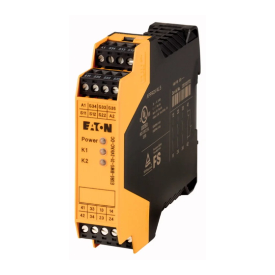
- Page 1 Manual 12/19 MN049005EN ESR5-BWS-31-24VAC-DC Safety relay...
- Page 2 No part of this manual may be reproduced, stored in a retrieval system, or transmit- ted in any form or by any means, electronic, mechanical, photocopying, micro-film- ing, recording, or otherwise, without the prior written permission of Eaton Industries GmbH, Bonn, Germany.
- Page 3 Danger! Dangerous electrical voltage! Before commencing the installation • Disconnect the power supply of the device. • Wherever faults in the automation system may cause damage to persons or property, external measures must • Ensure that devices cannot be accidentally retriggered. be implemented to ensure a safe operating state in the •...
-
Page 5: Table Of Contents
Two-channel emergency stop circuit without cross-circuit detection, with monitored reset button ............12 Single-channel emergency stop monitoring with monitored reset button................... 13 Two-channel safety door monitoring without cross-circuit detection, with monitored reset button ............14 Technical data ................15 Glossary ..................18 ESR5-BWS-31-24VAC-DC 12/19 MN049005EN www.eaton.com... - Page 6 ESR5-BWS-31-24VAC-DC 12/19 MN049005EN www.eaton.com...
-
Page 7: About This Manual
0 About This Manual 0 About This Manual This manual applies to the ESR5-BWS-31-24VAC-DC safety relay. 0.1 List of revisions The following significant amendments have been introduced since previous issues: Publication Page Keyword modified deleted date 12/19 First edition –... -
Page 8: Abbreviations And Symbols
Warns of the possibility of hazardous situations that could result in serious injury or even death. DANGER Warns of hazardous situations that result in serious injury or death. 0.4.3 Tips → Indicates useful tips. 0.5 Ordering data ESR5-BWS-31-24VAC-DC safety relay: Catalog No. 180413 ESR5-BWS-31-24VAC-DC 12/19 MN049005EN www.eaton.com... -
Page 9: Safety Notes
Risk of damage to equipment due to noise emissions When operating relay modules the operator must meet the requirements for noise emission for electrical and electronic equipment (EN 61000-6-4) on the contact side and, if required, take appropriate measures. ESR5-BWS-31-24VAC-DC 12/19 MN049005EN www.eaton.com... -
Page 10: Description
2 Description 2 Description The ESR5-BWS-31-24VAC-DC safety relay can be used to monitor electro- sensitive protective equipment with monitored active switching out- put (OSSD) in accordance with EN 61496 as well as emergency stop and safety door locking mechanisms. Depending on the external wiring, up to category 4, PL e according to EN ISO 13849-1 or SILCL 3 according to EN 62061 can be achieved. -
Page 11: Operating And Indication Elements
LED status indicator, green - K1 g LED status indicator, green - Power h A1, A2 - supply voltage connection i S33, S34, S35 - start circuit (activating circuit) j S11, S12, S22 - input circuit ESR5-BWS-31-24VAC-DC 12/19 MN049005EN www.eaton.com... -
Page 12: Basic Circuit Diagram
Supply voltage connection (+24 V DC, GND) S11, S12, S22 Input circuit S33, S34, S35 Start circuit 13/14 Undelayed enabling current path 1 23/24 Undelayed enabling current path 2 33/34 Undelayed enabling current path 3 41/42 Signaling current path ESR5-BWS-31-24VAC-DC 12/19 MN049005EN www.eaton.com... -
Page 13: Derating
5 Derating 5 Derating °C] Figure 3: Derating curve ESR5-BWS-31-24VAC-DC 12/19 MN049005EN www.eaton.com... -
Page 14: Diagnostics
No fault detection on initial start, only on first new demand. ● ○ ● Enable contact(s) of K1 faulty. Fault with internal ● ● ○ Enable contact(s) of K2 faulty. Replace safety relays. cause ● ○ ○ Enable contact(s) of K1 and K2 faulty. ESR5-BWS-31-24VAC-DC 12/19 MN049005EN www.eaton.com... -
Page 15: Application Examples
Alternatively: Automatic activation with jumper at S33-S35 • Suitable up to category 4, PL e (EN ISO 13849-1), SILCL 3 (EN 62061) (L1) Light grid type 4 Receiver OSSD1 OSSD2 ESR5-BWS-31-24VAC-DC ( + ) S33 S34 Reset (N ) Figure 4: Two-channel light grid monitoring ESR5-BWS-31-24VAC-DC 12/19 MN049005EN www.eaton.com... -
Page 16: Two-Channel Emergency Stop Circuit Without Cross-Circuit Detection, With Monitored Reset Button
Suitable up to category 3, PL d (EN ISO 13849-1), SILCL 2 (EN 62061) (L1) ① ESR5-BWS-31-24VAC-DC ( + ) ( ) ( ) Reset (N ) Figure 5: Two-channel emergency stop circuit without cross-circuit detection with monitored reset button a Emergency stop ESR5-BWS-31-24VAC-DC 12/19 MN049005EN www.eaton.com... -
Page 17: Single-Channel Emergency Stop Monitoring With Monitored Reset Button
Suitable up to category 1, PL c (EN ISO 13849-1), SILCL 1 (EN 62061) (L1) ① S11 S12 S22 ESR5-BWS-31-24VAC-DC ( ) ( ) S33 S34 S35 Reset (N ) Figure 6: Single-channel emergency stop circuit with monitored reset button a Emergency stop ESR5-BWS-31-24VAC-DC 12/19 MN049005EN www.eaton.com... -
Page 18: Two-Channel Safety Door Monitoring Without Cross-Circuit Detection, With Monitored Reset Button
Suitable up to category 3, PL d (EN ISO 13849-1), SILCL 2 (EN 62061) (L1) Safety door open closed ESR5-BWS-31-24VAC-DC ( ) ( ) S33 S34 S35 Reset (N ) Figure 7: Two-channel safety door monitoring without cross-circuit detection with monitored reset button ESR5-BWS-31-24VAC-DC 12/19 MN049005EN www.eaton.com... -
Page 19: Technical Data
Switching capacity (360 cycles/h) 6 A (24 V DC) 5 A (230 V AC) Switching capacity (3600 cycles/h) 3 A (24 V (DC-13)) 3 A (230 V (AC-15)) Output fuse 10 A gL/gG NEOZED (N/O contact) ESR5-BWS-31-24VAC-DC 12/19 MN049005EN www.eaton.com... - Page 20 Approvals Safety data Stop category according to IEC 60204 Safety parameters for IEC 61508 - High demand 5.56 x 10 per hour Demand rate 12 months Proof test interval 240 months Duration of use 240 months ESR5-BWS-31-24VAC-DC 12/19 MN049005EN www.eaton.com...
- Page 21 Safety parameters for IEC 61508 - Low demand MTTF 17913 years 1.50 x 10 Proof test interval 75 months Safety characteristic data according to EN ISO 13849 Category Performance Level Passed 1) Valid up to 8760 cycles per year ESR5-BWS-31-24VAC-DC 12/19 MN049005EN www.eaton.com...
-
Page 22: Glossary
Classification of the ability of safety functions to meet a safety demand Safety integrity level SILCL SIL claim limit SRCF Safety-related control function SRECS Safety-related electrical control system (Safety-related electrical, electronic, and programmable electronic control system) Safety-related part SRP/CS Safety-related parts of control system ESR5-BWS-31-24VAC-DC 12/19 MN049005EN www.eaton.com...
Need help?
Do you have a question about the ESR5-BWS-31-24VAC-DC and is the answer not in the manual?
Questions and answers