
Related Manuals for Paradyne bitstorm 4800


Summary of Contents for Paradyne bitstorm 4800
- Page 1 ™ BitStorm 4800 Installation Guide Document No. 4821-A2-GN20-00 April 2002...
- Page 2 Paradyne worldwide office locations, use one of the following methods: Internet: Visit the Paradyne World Wide Web site at www.paradyne.com. (Be sure to register your warranty at www.paradyne.com/warranty.) Telephone: Call our automated system to receive current information by fax or to speak with a company representative.
- Page 3 Important Safety Instructions 1. Read and follow all warning notices and instructions marked on the product or included in the manual. 2. This product is intended to be used with a 3-wire grounding type plug — a plug which has a grounding pin. This is a safety feature.
- Page 4 The authority to operate this equipment is conditioned by the requirements that no modifications will be made to the equipment unless the changes or modifications are expressly approved by Paradyne Corporation. CANADA – EMI NOTICE: This Class A digital apparatus meets all requirements of the Canadian interference-causing equipment regulations.
- Page 5 If trouble is experienced with the BitStorm 4800 , refer to the repair and warranty information on Page A. If the equipment is causing harm to the telephone network, the telephone company may request that you disconnect the equipment until the problem is resolved.
- Page 6 Japan Class A ITE This is a Class A product based on the standard of the Voluntary Control Council for interference by Information Technology Equipment (VCCI). If this equipment is used in a domestic environment, radio disturbance may arise. When such trouble occurs, the user may be required to take corrective actions.
-
Page 7: Table Of Contents
Installing the Mounting Brackets for Rack Mounting ....Installing the BitStorm 4800 Into a Rack ..... . . - Page 8 Using the CLI ......... Logging In to the BitStorm 4800......
-
Page 9: About This Guide
About This Guide Document Purpose and Intended Audience This document is written for technicians who install the BitStorm 4800 IP access concentrator, Model 4821. Document Summary Section Description Chapter 1, Installation Describes the physical installation of the BitStorm 4800 into a rack. -
Page 10: Related Product Documents
About This Guide Related Product Documents Documentation for the BitStorm 4800 IP access concentrator is available on the World Wide Web at www.paradyne.com. Select Library → Technical Manuals → BitStorm DSL Products. Document Number Document Title 4800-A2-GB20 BitStorm 4800 User’s Guide... -
Page 11: Installation
535 mm (21″) ETSI or 610 mm (24″) EIA rack. ETSI brackets are available from Paradyne. See Appendix B, Equipment List As many BitStorm 4800 units may be mounted in a standard rack as there are 44.45 mm (1.75″ ) spaces in the rack, so long as adequate cooling is provided. -
Page 12: Cables Required
8-position modular plug and An upstream BitStorm 4800 to 8-wire Category 5 or better a downstream BitStorm 4800, twisted pair cable. or the BitStorm 4800 to an adjunct server. DOWNLINK GigE (SFP) Duplex modular plug and An upstream BitStorm 4800 to fiber optic cable. -
Page 13: Unpacking The Hardware
The BitStorm 4800 is shipped in a cardboard shipping container. Carefully remove the unit from its shipping container and check for physical damage. If the unit shows signs of shipping damage, notify your sales representative. - Page 14 1. Installation Table 1-2. Contents of Hardware Kit Shipped with the BitStorm 4800 Appearance Description Quantity Self-retaining nut for racks without threaded holes Dress screw (12-24 x 1/2″ ) for use with self-retaining nuts Machine screw with captive starwasher (10-32 x 1/2″ )
-
Page 15: Mounting Configurations
Shelf or Desktop Installation The BitStorm 4800 may also be placed on a shelf or desktop. If you will not mount the BitStorm 4800 in a rack or on a wall, proceed to Installing the BitStorm 4800 on a Shelf or Desktop on page 1-12. -
Page 16: Mounting Brackets
BitStorm 4800. Both the supplied brackets and the optional ETSI brackets are marked LEFT SIDE and RIGHT SIDE, with reference to the left and right sides of the BitStorm 4800 when viewed from the front. For wall mounting, proceed to Installing the Mounting Brackets for Wall Mounting on page 1-10. -
Page 17: Installing The Mounting Brackets For Rack Mounting
1. Installation Installing the Mounting Brackets for Rack Mounting Procedure To install the mounting brackets for rack mounting: 1. Identify the flat-head screws provided in the hardware kit. Six screws are required for the 483 mm (19″) configuration, and four screws for the other configurations. -
Page 18: Installing The Bitstorm 4800 Into A Rack
Procedure To install the BitStorm 4800 into a rack: 1. Determine where in the rack you will mount the BitStorm 4800. If your rack does not have threaded screw holes, slip self-retaining nuts onto the rails where the BitStorm 4800 will be fastened. - Page 19 1. Installation 2. Place the BitStorm 4800 so that the brackets rest against the front of the rails. Insert screws in the bottom screw positions and hand-tighten them. 3. Insert and tighten the screws in the top screw positions, then tighten the bottom screws.
-
Page 20: Installing The Mounting Brackets For Wall Mounting
1. Installation Installing the Mounting Brackets for Wall Mounting Wall mounting requires two wood screws suitable for the weight of the fully cabled unit. These are not included. Use at a minimum 6 mm (.25″ ) diameter screws in 19 mm (.75″ ) plywood. Procedure To install the mounting brackets for wall mounting: 1. - Page 21 1. Installation 6. Install two wood screws (not provided) at the same height at least 760 mm (30″ ) above the floor and 453 mm (17.85″) apart. Do not completely tighten the screws. Leave them so their heads are about 6 mm (.25″ ) from the wall. 453 mm (17.85 in) 02-17147 7.
-
Page 22: Installing The Bitstorm 4800 On A Shelf Or Desktop
BitStorm 4800 in position. Procedure To install the BitStorm 4800 on a shelf or desktop, as a standalone unit or in a stack: 1. Locate the rubber feet in the hardware kit provided with the BitStorm 4800. -
Page 23: Installing The Management Module
1. Installation Installing the Management Module Each BitStorm 4800 requires a Model 4800 Management Module or a Model 4804 Management Module with V.35/X.21 uplink. If your Management Module was shipped separately from the BitStorm 4800, install the Management Module before you connect the BitStorm 4800 to a power source. - Page 24 3. Slide the Management Module into the guide rails just inside the opening. Press the Management Module firmly into place until it is fully seated and the faceplate of the Management Module is flush against the faceplate of the BitStorm 4800. Guide Rails 02-17069 4.
-
Page 25: Cabling
Cabling Cabling Overview The BitStorm 4800 has a large variety of possible cabling configurations. This chapter describes all possible connections, not all of which are required: DSL Ports on page 2-2 Downlink GigE Connectors on page 2-4 Uplink ports: —... - Page 26 2. Cabling DSL Ports The BitStorm 4800 has two DSL connectors, each supporting the tip and ring connections of up to 24 DSL ports over a 50-position cable. These must be connected to a POTS (plain old telephone service) splitter.
- Page 27 7. Secure the cables as required for strain relief. POTS Splitter Card in 1-Slot Chassis RT S 25 DS L PO RT S 1-2 DS L PO BitStorm 4800 Rear LIN K DO WN Gig E UP LIN POS ITIO Gig E...
- Page 28 The wiring is automatically detected and, if necessary, compensated for. A DOWNLINK GigE connector can be used to connect to: An adjunct server to provide caching, video on demand, or gateway services The UPLINK GigE connector of a downstream BitStorm 4800 (see Chaining Units Together...
-
Page 29: Uplink Options
Chaining Units Together page 2-8) An Ethernet switch, connected to the UPLINK GigE modular jack on the BitStorm 4800, or to a Small Form-factor Pluggable (SFP) transceiver plugged into the UPLINK GigE SFP socket, providing the appropriate interface: — 100BaseFX —... -
Page 30: Uplink Gige Connectors
2. Cabling Uplink GigE Connectors There are two UPLINK GigE connectors on the unit. Only one can be active. For the wire connection, either a straight-through or a crossover cable can be used. The wiring is automatically detected and, if necessary, compensated for. Procedure To connect to an Ethernet switch: 1. -
Page 31: V.35/X.21 Connector (4804 Management Module)
4. If you are using a short adapter and a separate cable, connect a cable to the adapter and fasten the two together with screws or cable ties. 5. If the BitStorm 4800 is in a rack, dress the cable to the left side of the rack, and fasten it to the rail with cable ties. -
Page 32: Chaining Units Together
2. Plug the other end of the cable into the UPLINK GigE jack of the next BitStorm 4800 in the stack. 3. If there is another BitStorm 4800 below this one in the logical stack, plug an 8-pin modular cable into the DOWNLINK GigE jack of this BitStorm 4800. -
Page 33: Management Port
1. Connect a modular 8-pin cable to the MGMT port. 2. If the BitStorm 4800 is in a rack, fasten the cable to a rail with a cable tie. 3. Connect the other end of the cable to your Ethernet hub or to a network interface card in a PC. -
Page 34: Console Port
2. Cabling Console Port The CONSOLE port on the Management Module normally serves as the primary user interface with the BitStorm 4800 during installation. Procedure To connect a terminal or PC to the CONSOLE port: 1. Configure the terminal or terminal emulation program to use the following parameters: —... -
Page 35: Modem Port
3. If the modem will be permanently connected, fasten the connector to the Management Module with its captive screws. If the BitStorm 4800 is in a rack, dress the cable to the left and attach it to the rail with a cable tie. -
Page 36: Alarm Port
To use the ALARM port: 1. Connect a modular 8-pin cable to the ALARM port. 2. If the BitStorm 4800 is in a rack, dress the cable to the left and secure it to the rail with a cable tie. -
Page 37: Grounding Lug
2. Cabling Grounding Lug Procedure To connect the unit to a ground: 1. Strip back the insulation approximately 8 mm (5/16″ ) on 14 AWG (2.08 mm copper ground wire. 2. Loosen the screw on the grounding lug located on the back panel next to the power switch. -
Page 38: Power Cord
1. Verify that the switch on the rear panel is in the Off (0) position. 2. Insert the power cord into the socket under the switch. 3. If the BitStorm 4800 is in a rack, dress the power cord to the left and fasten it to the rail with a cable tie. -
Page 39: Leds
LEDs LED Locations The small black rectangles in the following illustrations denote the locations of the front panel LEDs, including the LED on the 4804 Management Module. ALARM V.35/X.21 MODEM CONSOLE 4804 TEST ALARM 02-17086 Figure 3-1. V.35/X.21, System, and DSL Port LEDs 4821-A2-GN20-00 April 2002... - Page 40 3. LEDs UPLINK DOWNLINK GigE GigE MGMT STACK POSITION 02-17087 Figure 3-2. MGMT, UPLINK, DOWNLINK, and Stack Position LEDs April 2002 4821-A2-GN20-00...
-
Page 41: Front Panel Leds
3. LEDs Front Panel LEDs When power is first applied to the BitStorm 4800 it performs a self-test. When this test is successfully completed, the OK LED lights. The meaning of all the LEDs is as shown in Table 3-1, Front Panel LEDs. -
Page 42: System Leds
3. LEDs System LEDs The three system LEDs, OK, TEST, and ALARM, have meaning at all times, as shown in Table 3-2, System LEDs. Table 3-2. System LEDs ALARM TEST Description Unit is powered Off. Unit Failed – LEDs should never be in this state. Notify your service representative. -
Page 43: Configuration
Configuration Overview The BitStorm 4800 is designed to require minimal configuration before it can be accessed by a Network Operations Center (NOC). You may need to configure: The IP address for the Management Module if the default address (10.10.10.10) is not usable The default gateway address The data rate for the V.35/X.21 port, if used... -
Page 44: Using The Cli
4. Configuration Using the CLI The CLI provides automatic command completion. You need to type only enough of a command to make it unique. The CLI then completes each word in the command. For example, if you enter: sh man i the CLI expands it to: show management ip You can obtain help with CLI commands by typing a ? (question mark). -
Page 45: Logging In To The Bitstorm 4800
4. Configuration Logging In to the BitStorm 4800 When the BitStorm 4800 is turned on, the following prompt is displayed on the terminal: Login> Procedure To log in to the BitStorm 4800: 1. Type admin at the login prompt and press Enter. The following prompt is displayed: Password>... -
Page 46: Setting The Ip Address
4. Configuration Setting the IP Address The IP address of the Management Module must be set before the BitStorm 4800 can be remotely managed. Procedure To set the IP address of the Management Module: 1. At the IAC# prompt, type:... -
Page 47: Setting The Serial Interface Type And Rate
4. Configuration Setting the Serial Interface Type and Rate The 4804 Management Module has a DB25 interface (labeled V.35/X.21) that can be defined as V.35 (the default), EIA-530-A, or X.21. If you intend to use the connector for a V.35 or X.21 uplink, you must change the software setting. The V.35/X.21 port has a default rate of 2048 Kbps. - Page 48 4. Configuration April 2002 4821-A2-GN20-00...
-
Page 49: A Connectors, Cables, And Pin Assignments
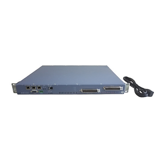
ALARM V.35/X.21 MODEM CONSOLE UPLINK DOWNLINK MGMT GigE GigE TEST ALARM STACK POSITION 02-17065-01 Figure A-1. BitStorm 4800 Front Panel (with 4804 Management Module) DSL PORTS 1-24 DSL PORTS 25-48 02-17066-01 Figure A-2. BitStorm 4800 Rear Panel 4821-A2-GN20-00 April 2002... - Page 50 A. Connectors, Cables, and Pin Assignments Management Port Connector The Management (MGMT) connector is an 8-pin unkeyed modular jack for a 10/100BaseT Pin 8 Pin 1 management interface. Either a straight-through or a crossover cable can be used. The wiring is 97-15449 automatically detected and, if necessary, compensated for.
-
Page 51: Ethernet Uplink And Downlink Connectors
A. Connectors, Cables, and Pin Assignments Ethernet Uplink and Downlink Connectors Ethernet UPLINK and DOWNLINK ports are provided in two forms: 8-pin modular jacks, and sockets for Small Form-factor Pluggable (SFP) transceivers. For the wire connection, either a straight-through or a crossover cable can be used. The wiring is automatically detected and, if necessary, compensated for. -
Page 52: Dsl Network Interface Cable
A. Connectors, Cables, and Pin Assignments DSL Network Interface Cable The 50-pin RJ21X Telco connectors at the rear of the BitStorm 4800 provide the 2-wire loop interface from each DSL port to the demarcation point. (The Canadian designation for this connector is CA21A.) There is one connector or two connectors... -
Page 53: V.35/X.21 (Eia-530-A) Port
A. Connectors, Cables, and Pin Assignments V.35/X.21 (EIA-530-A) Port The V.35/X.21 port is on the faceplate of the 4804 Management Module. It provides the EIA-530-A interface shown in Table A-4, V.35/X.21 (EIA-530-A) Port Interface Connector. Table A-4. V.35/X.21 (EIA-530-A) Port Interface Connector Circuit ITU-T Signal... -
Page 54: Eia-530-A To X.21 Interface
A. Connectors, Cables, and Pin Assignments EIA-530-A to X.21 Interface The EIA-530-A to X.21 adapter (4800-F1-502) or adapter cable (4800-F1-503) are DB25-to-DB15 connectors that, connected to the V.35/X.21 port of the 4804 Management Module, provide the X.21 interface shown in Table A-5, X.21 Cable Interface. - Page 55 A. Connectors, Cables, and Pin Assignments Table A-5. X.21 Cable Interface ITU-T Signal Number Direction Signal Common — Transmitted Data To DSU/CSU 2 (A) 9 (B) Received Data From DSU/CSU 4 (A) 11 (B) Request to Send To DSU/CSU 3 (A) 10 (B) Data Channel Received Line Signal Detector From DSU/CSU...
-
Page 56: Eia-530-A To V.35 Interface
A. Connectors, Cables, and Pin Assignments EIA-530-A to V.35 Interface The EIA-530-A to V.35 adapter (4800-F1-500) and adapter cable (4800-F1-501) are DB25-to-MS34 connectors that, connected to the V.35/X.21 port of the 4804 Management Module, provide the V.35 interface shown in Table A-6, V.35 Cable Interface. - Page 57 A. Connectors, Cables, and Pin Assignments Table A-6. V.35 Cable Interface ITU-T Signal Number Direction Shield — — Signal Common — Transmitted Data To DSU/CSU P (A) S (B) Received Data From DSU/CSU R (A) T (B) Request to Send To DSU/CSU Clear to Send From DSU/CSU...
-
Page 58: Alarm Port
A. Connectors, Cables, and Pin Assignments Alarm Port The alarm relay reports major alarms through the ALARM port on the faceplate of the 4800 or 4804 Management Module. The ALARM port is an 8-pin modular connector; only Pins 2, 3, and 4 may be used. Maximum ratings for the ALARM connector are: 30 VAC 60 VDC... -
Page 59: Modem Port Connector
A. Connectors, Cables, and Pin Assignments Modem Port Connector The MODEM port connector is a DB9 female connector on the faceplate of the 4800 or 4804 Management Module. It supports an EIA-232 circuit as shown in Table A-8, Modem Port Connector. - Page 60 A. Connectors, Cables, and Pin Assignments A-12 April 2002 4821-A2-GN20-00...
- Page 61 Model Number Allied Data ADSL Modem – 10BaseT Ethernet and USB port CJ810 BitStorm 4800 (48-Port) 4821-A1-440 Includes BitStorm 4800, mounting brackets and hardware, and Installation Guide. BitStorm 4800 (48-Port, with Management Module and V.35/X.21 4821-A1-441 Uplink) Includes BitStorm 4800 with Model 4804-B1-000 Management Module installed, EIA-530-A to V.35 Adapter, mounting brackets and...
- Page 62 B. Equipment List Table B-1. Equipment List (2 of 2) Description Model Number Management Module 4800-B1-000 Includes Installation Instructions. Mounting Brackets for ETSI 535 mm (21″) Rack 4800-F1-011 Splitter Block for ADSL KHZ-023-6625FF Subscriber Gateway Server 901-1011-001 April 2002 4821-A2-GN20-00...
-
Page 63: Technical Specifications
Table C-1. Technical Specifications (1 of 2) Specifications Criteria Cooling and Air Each BitStorm 4800 is independently cooled with integral fans and Handling does not rely on vertical air flow. Electrical Safety All interfaces are Safety Extra-Low Voltage (SELV) circuits except:... - Page 64 C. Technical Specifications Table C-1. Technical Specifications (2 of 2) Specifications Criteria Interfaces BitStorm 4800: DSL PORTS (2): 50-pin RJ21X Telco-type connector DOWNLINK GigE: – 8-pin modular jack (10/100/1000BaseT) – Small Form-factor Pluggable (SFP) socket (1000BaseX) UPLINK GigE: – 8-pin modular jack (10/100/1000BaseT) –...
- Page 65 Index adapter data rate, configuring, 4-5 EIA-530-A to V.35, A-8 default EIA-530-A to X.21, A-6 gateway, 4-4 installing, 2-7 password, 4-3 administrator desktop installation, 1-12 login, 4-3 dimensions, C-2 mode, 4-3 document purpose, iii ALARM port documents cabling, 2-12 related, iii description, 1-2 downlink and uplink pin assignments, A-3 pin assignments, A-10...
- Page 66 Index gateway, 4-4 operating environment, C-2 glossary URL, iii optional mounting brackets, 1-5 grounding lug, 2-13 order numbers, B-1 overview configuration, 4-1 of book, iii hardware kit contents, 1-4 package contents, 1-3 installation options, 1-1 part numbers, B-1 installing password, 4-3 feet for shelf installation, 1-12 PC cabling and settings, 2-10 in rack, 1-8...
- Page 67 Index specifications related, iii V.35 adapter subnet mask, 4-4 installing, 2-7 synopsis of chapters, iii V.35/X.21 port system LEDs, 3-1 cabling, 2-7 configuring interface type and rate, 4-5 description, 1-2 technical specifications, C-1 pin assignments, A-5 Telco connectors V.35 adapter, A-8 fastening, 2-2 X.21 adapter, A-6 terminal cabling and settings, 2-10...
- Page 68 Index IN-4 April 2002 4821-A2-GN20-00...
Need help?
Do you have a question about the bitstorm 4800 and is the answer not in the manual?
Questions and answers