Elcometer 331 SH Operating Instructions Manual
Concrete covermeter
Hide thumbs
Also See for 331 SH:
- Operating instructions manual (39 pages) ,
- Operating instructions manual (41 pages)
Table of Contents
Advertisement
Quick Links
Advertisement
Table of Contents

Related Manuals for Elcometer 331 SH


Summary of Contents for Elcometer 331 SH
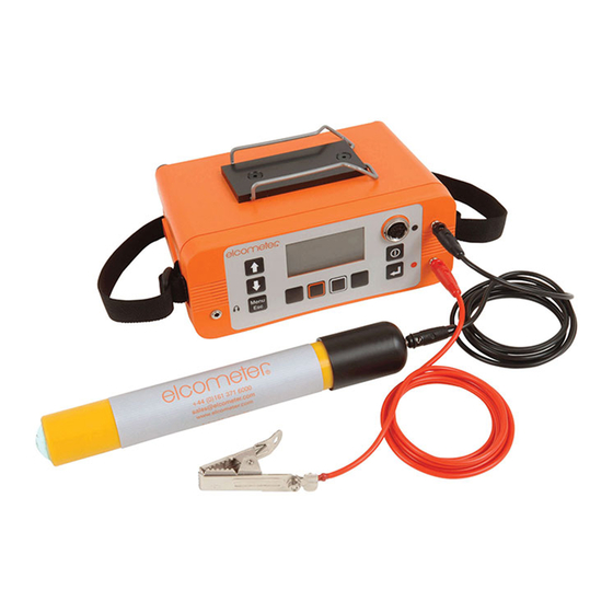
- Page 1 Elcometer 331 Concrete Covermeter Model SH • Model TH Operating Instructions...
- Page 2 (in a retrieval system or otherwise) or translated into any language, in any form or by any means (electronic, mechanical, magnetic, optical, manual or otherwise) without the prior written permission of Elcometer Limited. A copy of this Instruction Manual is available for download on our Website via www.elcometer.com/ downloads. Doc.No. TMA-0384 Issue 04...
-
Page 3: Table Of Contents
CONTENTS Section Page About your Covermeter..........1 Quick-start . - Page 4 11.3 Under Cover ............35 Setting limits .
-
Page 5: About Your Covermeter
Our coatings products cover all aspects of coating inspection, from development through application to post application inspection. The Elcometer 331 Concrete Covermeter is a world beating product. With the purchase of this Covermeter you now have access to the worldwide service and support network of Elcometer. For more information visit our website at www.elcometer.com... - Page 6 Stainless steel reinforcement bar detection and measurement Upgradeable Note: Features described in these instructions apply to all models unless otherwise indicated in the text. 1.2 What this box contains • Elcometer 331 Model SH or Model TH Concrete Covermeter • Search head connecting cable •...
-
Page 7: Quick-Start
START Figure 1. Elcometer 331 Concrete Covermeter 1.3 Standards The Elcometer 331 Concrete Covermeter can be used in accordance with the following National and International Standards: BS1881:204, ASTM C876, DGZfP:B2, DGZfP:B3, TR60, UN110174 1.4 Conventions in these instructions A simple menu structure helps you get the most from your Covermeter - see “The menus” on page 13. -
Page 8: Getting Started
Covermeter. One battery pack is supplied with the Covermeter. To increase productivity on site, Elcometer recommends that you purchase a spare battery pack which can be charged while you are using your Covermeter. - Page 9 ETTING STARTED The Covermeter will automatically switch off when the lead from the charger is connected. (battery in the Covermeter) (battery removed) Figure 3. Charging the batteries 3. Plug the charger supplied into the mains supply. The LED indicator on the charger will glow orange.
-
Page 10: Fitting Search Heads
ETTING STARTED 3.2 Fitting search heads The Covermeter must be switched off when search heads are fitted or removed. Connect the search head to the Covermeter using the supplied connecting cable. The connecting cable is fitted with a metal screw-type connector at each end. To fit a connector, align the keyway, push the connector into place and then tighten the metal collar. -
Page 11: Fitting Half-Cell Probes
ETTING STARTED search heads are larger and do not fit in the rails. Each head is fitted with a label which identifies its type for ease of recognition. The software also shows an indication of the search head type as indicated in section 3.2. -
Page 12: The Controls
ETTING STARTED 3.5 The controls All functions of the Covermeter can be controlled using the keypad on the main unit. There are two types of keys on the keypad; fixed function keys and ‘soft’ keys (Figure 6).. Scrolls up/down through menus and lists of values Increases/ Switches the... -
Page 13: Switching The Covermeter On And Off
ETTING STARTED 3.6 Switching the Covermeter on and off Note: Before switching the Covermeter on for the first time read “Selecting a language” on page 11. To switch the Covermeter on, press [ To switch the Covermeter off, press and hold [ ] for two seconds. - Page 14 ETTING STARTED Reading screen (when measuring depth of cover) 1. Statistics (37) 9. Zero softkey 2. Signal strength indicator bar (18) 10. Size softkey 3. Batch name/Cell coordinates (40) 11. Search head type (6) 4. Bar size/number - input by user (25) 12.
-
Page 15: Selecting A Language
3.8 Selecting a language Your Covermeter has a number of built-in languages. When the Covermeter is switched on for the first time after dispatch from the Elcometer factory the display will show the language selection screen (Figure 8). At first switch on 1. -
Page 16: Using The Earphone
ETTING STARTED 3.10 Using the earphone To use the earphone, plug the connector into the 3.5 mm socket marked on the front of the Covermeter. Replacement earphones are available as an optional accessory - see “Accessories” on page 64. 3.11 Zeroing the Covermeter This action is requested by the Covermeter whenever it is switched on with a search head attached, when a cover batch is opened, on entering orthogonal SIZE mode, and periodically thereafter (at least once every 10 minutes). -
Page 17: The Menus
HE MENUS 4 THE MENUS To access the menus press the MENU softkey. To return to the reading screen quickly, press and hold the MENU softkey. - Page 18 CURRENT STATISTICS ..Prints or outputs to PC the current statistics See “Transferring readings to a computer” on page 52 ‘Plot batch’ - available on Elcometer 331 Model TH only. ‘Plot options’ - available on Elcometer 331 Model TH only.
- Page 19 PROBE INFORMATION ..Press Enter to display technical information about the search head CONTACT ....Press Enter to display Elcometer offices worldwide and (if programmed) Supplier contact details HELP .
- Page 20 Note: RS232 Bit Image and RS232 Plain Text cannot be toggled to ‘on’ at the same time. See “Transferring readings to a computer” on page 52 ‘Blank’ - available on Elcometer 331 Model TH only. ‘Clock’ - available on Elcometer 331 Model TH only.
- Page 21 19200....Select using Scroll keys and press Enter to select m. ‘Show time’ - available on Elcometer 331 Model TH only. ‘Set threshold’ - available on Elcometer 331 Model TH only.
-
Page 22: Locating Reinforcement Bars
OCATING REINFORCEMENT BARS 5 LOCATING REINFORCEMENT BARS This section describes how to set up and use your Covermeter to locate reinforcement bars. 5.1 Before you start • Are you using the correct search head? See “Search heads” on page 55. 5.2 To locate a single layer of reinforcement bars 1. -
Page 23: To Locate Two Layers Of Reinforcement Bars
OCATING REINFORCEMENT BARS • The signal strength indicator bar on the display will increase in length. • The depth of cover on the display will show a number. • The LED on the search head will start to glow. The search head is aligned directly over a reinforcement bar when: •... -
Page 24: To Determine The Orientation Of A Reinforcement Bar
OCATING REINFORCEMENT BARS • The second scan locates the nearer (top) layer. First scan Second scan Figure 11. Scanning layers of bars of different size (This situation is typical of a nearer layer consisting of relatively thin tie-wires or stirrups, and the deeper layer consisting of much larger main structural bars.) 5.4 To determine the orientation of a reinforcement bar 1. -
Page 25: Surface Mapping
OCATING REINFORCEMENT BARS can see. A block of wood or plastic 20 mm to 45 mm thick can be held between the search head and the bars to simulate the depth of concrete cover. Start from the simplest situation, a single straight bar, and progress through parallel bars, lapped bars, and crossing bars. -
Page 26: Measuring Depth Of Cover
EASURING DEPTH OF COVER 6 MEASURING DEPTH OF COVER This section describes how to set up and use your Covermeter to measure the depth of cover over reinforcement bars. 6.1 Before you start • Are you using the correct search head? See “Search heads”... -
Page 27: What Happens When You Press Enter [ ]
MENU / SETUP / LIMITS). Figure 13. Beeps (*) and scrolling on a 6x3 grid batch Grid batches - available on Elcometer 331 Model TH only. The LED in the search head will also flash to indicate an ‘out of limits’ reading. -
Page 28: Accuracy
EASURING DEPTH OF COVER 6.4 Accuracy The reading of cover will only be accurate if all the following conditions are satisfied: • The instrument has been zeroed. • The search head is over the centre-line of the bar. • The search head is parallel to the bar. •... -
Page 29: Selecting Bar Size
ELECTING BAR SIZE 7 SELECTING BAR SIZE The dimensions of reinforcement bars are stored within the Covermeter. The dimensions are grouped into four standard series; Metric, Imperial, ASTM/Canadian and Japanese. To select bar size, display the reading screen and press the BAR softkey to access Bar Size selection: •... -
Page 30: Autosizing
IZING 8 AUTOSIZING Your Covermeter includes AutoSize - a feature which automatically calculates an estimate of the size of a reinforcement bar and the depth of cover. The autosize estimated values are displayed on the reading screen in a small font size alongside standard readings. Bar size Depth of cover Figure 15. -
Page 31: Measuring Size Of Reinforcement Bars Orthogonal
EASURING SIZE OF REINFORCEMENT BARS ORTHOGONAL 9 MEASURING SIZE OF REINFORCEMENT BARS (ORTHOGONAL) Although the Covermeter includes the AutoSize feature (see page 26), a separate ‘orthogonal’ SIZE function is included for accurate measurement of bar size. The orthogonal SIZE function is intended to be used to determine the diameter of a (single) reinforcement bar. - Page 32 EASURING SIZE OF REINFORCEMENT BARS ORTHOGONAL 9. Position the search head parallel and in line with the reinforcement bar (Figure 16). The sound/ signal will be at a maximum. Figure 16. Search head parallel and in line with bar 10. Press [ ]. The display will show: 11.
-
Page 33: Accuracy
EASURING SIZE OF REINFORCEMENT BARS ORTHOGONAL 13. If you are satisfied with the bar size, press [ ] to set the Covermeter to use this size. If you are not satisfied with the bar size, press [menu/esc] to return to the reading screen without making any changes. -
Page 34: Reducing Errors When Orthogonal Sizing
EASURING SIZE OF REINFORCEMENT BARS ORTHOGONAL 9.4 Reducing errors when orthogonal sizing This technique improves the accuracy of orthogonal sizing of bars where the nearest parallel bars appear to be adequately distant, but the transverse bars are closer together . This situation is illustrated in Figure 18 where position X is the measurement position. -
Page 35: Measuring Half-Cell Potential
EASURING HALF CELL POTENTIAL 10 MEASURING HALF-CELL POTENTIAL Your Covermeter is capable of measuring half-cell potential - an electrochemical technique commonly used to assess the severity of corrosion in reinforced concrete structures. When set to half-cell mode, your Covermeter acts as a voltmeter which measures the potential difference between the steel reinforcement in the concrete structure and a reference electrode (the half-cell) placed on the surface of the concrete. -
Page 36: What Happens When You Press Enter [ ]
MENU / SETUP / LIMITS). Model TH: Grid batches - available on Elcometer 331 Model TH only. Typically, a low limit will be applied at the threshold that would indicate corrosion e.g. -350 mV. Any readings lower (more negative) than this would then cause an alarm and be tagged as below limit in the statistics and/... -
Page 37: Measuring Cell-To-Cell Rather Than Cell-To-Bar
OUND MODE ETECTION MODE • Single beep - reading taken. • Double beep - reading taken in last memory location of a row in a grid. • Triple beep - reading taken in last memory location of the grid. • Triple beep (higher pitch) - reading taken is outside limits if limits have been set MENU / SETUP / LIMITS). -
Page 38: Locate
OUND MODE ETECTION MODE Your Covermeter has three sound/detection modes; Locate, Maxpip™ and Under Cover. MENU / SETUP / SOUND MODE SOUND MODE LOCATE MAXPIP UNDER COVER 11.1 Locate In this mode, the pitch of the sound from the Covermeter increases as the search head gets closer to a bar. -
Page 39: Maxpip
OUND MODE ETECTION MODE 11.2 Maxpip™ This is an alternative method of locating the centre of each reinforcement bar. In this mode, an audio 'pip' is given each time the middle of a reinforcement bar is detected as the surface is scanned. An icon on the main measurement display indicates that Maxpip™... -
Page 40: Setting Limits
ETTING LIMITS 12 SETTING LIMITS Low and High limits can be set by the user to monitor whether depth of cover or half-cell potential is within specifications. MENU / SETUP / LIMITS LOW LIMIT HIGH LIMIT LOW LIMIT ON HIGH LIMIT ON LOW LIMIT mm/mV HIGH LIMIT... -
Page 41: Statistics
TATISTICS 13 STATISTICS Your Covermeter has a Statistics feature which calculates and displays a statistical analysis of readings as they are taken. Statistics values are also calculated for the readings within a batch and these values are stored in the batch. To enter a reading into the statistical analysis while you are taking measurements, press [ ]. - Page 42 Resets to zero all statistical values. Press YES to confirm or NO to cancel. Clear stats is not available while a batch is open ‘Blank readings’ - Elcometer 331 Model TH only. aa. Opening a new or existing batch will also cause all current statistical values to be reset to zero.
- Page 43 HIGHEST READING MENU / STATISTICS / ENLARGE STATS / ALL UNDER RANGE On Elcometer 331 Model TH, the selected statistics values BELOW LIMIT will only be displayed on the reading screen if the display ABOVE LIMIT of time and date is not selected:...
-
Page 44: Batching/Data Logging
200 (Model TH Covermeters) 14.2 Grid batches Note: The instructions given in this section (14.2) apply to Elcometer 331 Model TH only. Users of Elcometer 331 Model SH can upgrade their instrument to model TH to gain this functionality - contact Elcometer or your local supplier for details. -
Page 45: What Does A Batch Contain
ATCHING ATA LOGGING • Use the Covermeter to locate and measure the minimum area of cover within each grid cell, or the cover to the reinforcement bar nearest to each grid-point, depending upon your survey procedures. • Store the results in a grid batch corresponding to the grid of squares (press [ ] to enter a reading while the batch is open). - Page 46 ATCHING ATA LOGGING Table 2: Batch contents Entered by Symbol Symbol meaning Typical contents User CU/CUSO4 Half-cell type AG/AGCL Temperature 20° C Engineer M. Smith Highways Customer Department Lowest reading Highest reading Mean Standard deviation Number and percentage of readings below the x (y%) <...
-
Page 47: Saving Your Readings In Memory
If a new batch is created with a name and type matching an existing batch, the instrument beeps and returns to the name editing screen. Note: Column, rows and grid spacing - Elcometer 331 Model TH only. 14.4 Saving your readings in memory... -
Page 48: Clone Batch/Copy Batch Information
ATCHING ATA LOGGING 2. Press [ ] to select the batch. When the batch has been opened, the display switches to the reading screen and then starts batching (the BATCH softkey appears on the reading screen). Readings in the existing batch can then be amended, deleted and added. 3. -
Page 49: Plot Batch
(TH models only), • and then return to the reading screen ready to take more measurements in the same batch. ad. ‘Plot batch’ - Elcometer 331 Model TH only. ae. ‘Plot options’ - Elcometer 331 Model TH only. - Page 50 ATCHING ATA LOGGING Pressing BATCH displays the Reading Review Screen. REVIEW readings using the scroll keys to move around the contents of a batch. Press and hold the Shift softkey [ ] and then press any of the Scroll keys to jump quickly to the start or end of line of readings. Figure 23.
-
Page 51: How To Enter Information Into Batch Header Fields
ATCHING ATA LOGGING 14.17 How to enter information into batch header fields You can enter information into the header fields when you first open (create) a new batch or clone a batch and when editing batch tags. There are two methods of entering information into the header fields of a batch; •... -
Page 52: Typical Survey (Using Grid Batch Memory)
TYPICAL SURVEY USING GRID BATCH MEMORY 15 A TYPICAL SURVEY (USING GRID BATCH MEMORY) This section leads you step-by-step through taking measurements, saving cover and half-cell readings in batches and producing a report. The instructions are for a model TH; users of a model SH will be limited to linear batches only. -
Page 53: Plotting Batches
LOTTING BATCHES 16 PLOTTING BATCHES Note: The instructions given in this section (16) apply to Elcometer 331 Model TH only. Users of Elcometer 331 Model SH can upgrade their instrument to model TH to gain this functionality - contact Elcometer or your local supplier for details. -
Page 54: Plot Options
LOTTING BATCHES Use the arrows to scroll the cursor around the plot; as the cursor moves the current memory location and reading are shown at the top right of the display. Large batches will scroll when the cursor reaches the edge of the display. Use the Zoom softkey to zoom in to areas of interest. -
Page 55: Measuring Welded Mesh And Joined Bars
EASURING WELDED MESH AND JOINED BARS 17 MEASURING WELDED MESH AND JOINED BARS The procedures for locating and measuring depth of cover of welded mesh and joined bars are similar to those for reinforcement bars as described in sections 5, 6 and 9 (pages 18 to 24 and 27 to 30). -
Page 56: Transferring Readings To A Computer
Baud Rate. This can be set at values from 1200 to 19200. The default value is 9600 baud. RS232 Bit Image. Toggle tick box to activate/deactivate. All images and characters are output as bit-maps. This allows printing on the Elcometer Miniprinter (see “Accessories” on page 64). - Page 57 Covermeter. CoverMaster is powerful but easy-to-use software which simplifies setting up and using your Covermeter: • Design batch templates on your PC and download these to your Elcometer 331 Covermeter, ready for use on site. ® • Download cover and half-cell readings data from your Covermeter to the CoverMaster data management system.
- Page 58 RANSFERRING READINGS TO A COMPUTER Batch templates Batch readings ® CoverMaster interface showing reading data (measurements) ® CoverMaster interface showing topographical representation of the same reading data ® Figure 30. Use CoverMaster to link your Covermeter to a computer...
-
Page 59: Search Heads
Mean Average: 35 mm Standard Deviation: 14 mm Max: 56 mm Min: 5 mm Printed on 29/03/2005 0.20 Elcometer CoverMaster Software Range: 51 mm www.elcometer.com Page 1 Readings Below Low Limit: 0.40 Readings Above High Limit: 0.60 Percent Below Low Limit: 28.81%... - Page 60 EARCH HEADS All search heads are fully interchangeable. Changing from one type of search head to another is quick and easy; simply switch off the Covermeter, swap search heads, switch on again and zero the Covermeter. Narrow Pitch Standard Deep Cover Borehole Probe Figure 32.
- Page 61 EARCH HEADS Figure 33. Borehole probe search fields The body of the probe has a scale marked every 10 mm (0.5") along its length. Use this scale to measure the depth of reinforcement bars located to one side of the hole. The scale indicates distance from the centre of the sideways looking sensor in the probe.
- Page 62 EARCH HEADS 19.1 Search head extension arm This optional accessory allows the operator simple access to areas normally requiring ladders or scaffolding. The search head extension arm reduces the need to kneel down and allows the user to scan bridge decks and floor areas from a standing postion.
-
Page 63: Half-Cell Probes
CELL PROBES 20 HALF-CELL PROBES Two types of half-cell probe are available for your Covermeter. The probes can be easily identified by colour: • Copper-Copper Sulphate (Cu-CuSO ): Yellow • Silver-Silver Chloride (Ag-AgCl): Blue 20.1 Wetting your probe For your probe to function properly the ceramic sensing end (the electrode) must be wet. To get a good wet electrode, just place the electrode in tap water for two to three minutes;... -
Page 64: Error Messages
Numerical error. LARGE If error persists contact Elcometer. CLOCK Internal error. Return to Elcometer*. LANGUAGE Software error. Return to Elcometer*. MEMORY * Contact Elcometer or your Elcometer Supplier to arrange return. Figure 35. Example error message - search head not connected... -
Page 65: Personalised Welcome Screen
Elcometer or your Elcometer supplier. The Covermeter does not contain any user-serviceable components. In the unlikely event of a fault, the Covermeter should be returned to your Elcometer supplier or directly to Elcometer. The warranty will be invalidated if the gauge has been opened. -
Page 66: Upgrading Your Covermeter
16 mm (#5) diameter bar at 100 mm (4") depth of cover; pitch ≥ 125 mm (5") am. All performance figures have been obtained when using Elcometer reference rebars of standard diameter at room temperature. an. Accuracy figures for the deep cover search head are obtained once the operating temperature has... -
Page 67: Power Supply
Battery life: Up to 32 hours continuous use without backlight. Up to 20 hours with backlight. 27 RELATED EQUIPMENT Elcometer produces a wide range of concrete and coatings inspection equipment. Users of the Elcometer 331 Concrete Covermeter may also benefit from the following Elcometer products: •... -
Page 68: Accessories
Your Covermeter is complete with all the items required to get started. The following optional accessories are available from Elcometer, or your Elcometer supplier. To place an order please quote the sales part number which follows the description of each accessory. -
Page 69: Index
Depth of cover Manual selection of Detection mode Measurement of Dimensions BATCH Batch Cloning Earphone Copying Earphones Deleting all Elcometer 331 Deleting one Features Opening existing Overview Opening new Enter key Recalculation What it does Batches Entering information For Cover and Half-cell... - Page 70 NDEX Specifications AUTO SWITCH OFF Storage and Shelf life BACKLIGHT Wetting Header fields BATCH Entering information BAUD RATE 17, 52 BEEP VOLUME CLEAR STATS Imperial bar size CLOCK Interface CLONE BATCH Access cover CONTACT RS232 COVER CURRENT STATISTICS DATA LOGGER 14, 43 Japanese bar size DELETE ALL BATCHES...
- Page 71 NDEX UNITS Overview ZERO Standard Menus Specifications Metric bar size Storage clip Muting the sound Sensitivity Size Measurement Narrow Pitch search head Borehole Probe 56, 57 Measuring Automatic On/off Orthogonal Open existing batch Welded mesh Open new batch Size (orthogonal) Opening screen Failure of Creating...
- Page 72 NDEX Zoom...
Need help?
Do you have a question about the 331 SH and is the answer not in the manual?
Questions and answers