Elcometer Protovale 331 Operating Instructions Manual
Concrete covermeter
Hide thumbs
Also See for Protovale 331:
- Operating instructions manual (44 pages) ,
- Operating instructions manual (41 pages)
Table of Contents
Advertisement
Quick Links
Advertisement
Table of Contents

Related Manuals for Elcometer Protovale 331


Summary of Contents for Elcometer Protovale 331
- Page 1 Elcometer Protovale 331 Concrete Covermeter Model T Operating Instructions...
- Page 2 The Elcometer Protovale 331 Concrete Covermeter has been tested in accordance with regulations governing Electro-magnetic compliance and it meets the required directives. Note: Readings may be affected if the unit is operated within a radio frequency electromagnetic strength of greater than 3 V/m.
-
Page 3: Table Of Contents
ONTENTS CONTENTS Section Page About your Covermeter........1 Quick-start . - Page 4 ONTENTS Sound mode/Detection mode ......34 10.1 Locate ..........34 10.2 Maxpip™...
-
Page 5: About Your Covermeter
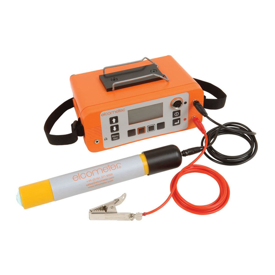
BOUT YOUR OVERMETER hank you for your purchase of this Elcometer Protovale 331 Model T Concrete Covermeter. Welcome to Elcometer. Elcometer are world leaders in the design, manufacture and supply of inspection equipment for concrete and coatings. Our concrete inspection products include a comprehensive range of concrete, and civil engineering inspection equipment. - Page 6 CoverMaster software for batch setup, data transfer and report generation • Upgradeable 1.2 What this box contains • Elcometer Protovale 331 Model T Concrete Covermeter • Standard search head • Search head connecting cable • Rechargeable battery pack and battery charger •...
- Page 7 BOUT YOUR OVERMETER Figure 1. Elcometer Protovale 331 Model T Concrete Covermeter 1.3 Standards The Elcometer Protovale 331 Model T Concrete Covermeter can be used in accordance with the following National and International Standards: ACI 318 BS1881:204 CP 110 DIN 1045 SIA 162 1.4 Conventions in these instructions...
-
Page 8: Quick-Start
Covermeter. One battery pack is supplied with the Covermeter. To increase productivity on site, Elcometer recommends that you purchase a spare battery pack which can be charged while you are using your Covermeter. To order an additional battery pack (see “Accessories”... - Page 9 ETTING STARTED 1. Referring to Figure 2, unscrew the retaining screw (1) and open the interface access cover (2) on the rear of the Covermeter. Battery Pack Elcometer Offices Li-Ion 7.4V See Charging Instructions www.elcometer.com Made In England Figure 2. Covermeter rear panel 2.
-
Page 10: Fitting Search Heads
ETTING STARTED Do not allow metallic objects to come into contact with the battery terminals; this may cause a short circuit and result in permanent damage to the battery. Battery condition indicator The state of charge of the battery is shown by a symbol on the display: Symbol Battery charge/action required 70% to 100%... -
Page 11: The Controls
All functions of the Covermeter can be controlled using the keypad on the main unit. There are two types of keys on the keypad; fixed function keys and ‘soft’ keys (Figure 5). Menu ALL DIMENSIONS IN m.m. ‘Soft’ keys Fixed function keys Figure 5. Elcometer Protovale 331 Concrete Covermeter main keypad... - Page 12 ETTING STARTED Fixed function keys Name Functions Scroll Scrolls up through menus and lists of values Increases alphanumeric values Increases sensitivity in locate mode Scroll Scrolls down through menus and lists of values Down Decreases alphanumeric values Decreases sensitivity in locate mode Menu/ Accesses menus Menu...
- Page 13 ETTING STARTED Search head keypad The search head is fitted with a keypad which mimics the functions of some of the keys on the main unit. Use the keys on the search head in the same way as you use the keys on the main unit. The function of the Enter and Menu/Esc Menu...
-
Page 14: Switching The Covermeter On And Off
ETTING STARTED 3.4 Switching the Covermeter on and off Note: Before switching the Covermeter on for the first time read “Selecting a language” on page 12. To switch the Covermeter on, press To switch the Covermeter off, press and hold for two seconds. - Page 15 ETTING STARTED The main screen displayed (while you are taking measurements) is the Reading Screen. The components of the reading screen are described below: Signal strength indicator bar (19) Statistics (38) Batch name/Cell coordinates (46) Battery condition indicator (6) Bar size/number - input by user (27) Depth of cover (24) Sensitivity/Maxpip™/Under Cover (34) Search head type (6)
-
Page 16: Selecting A Language
Your Covermeter has a number of built-in languages. When the Covermeter is switched on for the first time after dispatch from the Elcometer factory the display will show the language selection screen (Figure 7). At first switch on Figure 7. Language selection screen 1. -
Page 17: Computer Interface
ETTING STARTED 4. Release left hand softkey. 5. Press to locate language required. 6. Press to activate the selected language. Alternatively, select a language at any time. MENU / SETUP / LANGUAGE 3.7 Computer interface Your Covermeter is fitted with an RS232 interface. The interface is located under the interface access cover at the rear of the Covermeter - see Figure 2 and Figure 3 on page 5. -
Page 18: The Menus
HE MENUS 4 THE MENUS To access the menus press the MENU softkey. To return to the reading screen quickly, press and hold the MENU softkey. - Page 19 HE MENUS 4.1 MENU DATA LOGGER..Opens Data logger menu ..See 4.2 DATA LOGGER BACKLIGHT ... Toggles the display backlight on or off STATISTICS .
- Page 20 PROBE INFORMATION . .Press Enter to display technical information about the search head CONTACT ... . .Press Enter to display Elcometer offices worldwide and (if programmed) Supplier contact details HELP ....Press Enter to display an explanation of all the symbols used on the display 4.7 RESET...
- Page 21 HE MENUS 4.8 SELECT STATS NO. OF READINGS ..Press Enter to toggle on or off MEAN ....Press Enter to toggle on or off STD DEVIATION .
- Page 22 HE MENUS 4.13 DISPLAY SHOW TIME ...Press Enter to toggle on or off STATS ON LCD..Press Enter to toggle on or off SHOW AUTOSIZE INFO .
-
Page 23: Locating Reinforcement Bars
OCATING REINFORCEMENT BARS 5 LOCATING REINFORCEMENT BARS This section describes how to set up and use your Covermeter to locate reinforcement bars. 5.1 Before you start • Are you using the correct search head? See “Search heads” on page 57. 5.2 To locate a single layer of reinforcement bars 1. -
Page 24: To Locate Two Layers Of Reinforcement Bars
OCATING REINFORCEMENT BARS When the search head is approaching a reinforcement bar: • The Covermeter will start to emit a sound which will increase in pitch as the search head moves closer to the bar. • The signal strength indicator bar on the display will increase in length. •... - Page 25 OCATING REINFORCEMENT BARS If the bars in the nearer layer are thin compared with those in the deeper layer (Figure 10): Search for the deeper layer first; it gives a stronger signal, and is least influenced by the other bars. Then search for the nearer layer, this time scanning the head in lanes between the now-known positions of the deeper layer of bars.
-
Page 26: To Determine The Orientation Of A Reinforcement Bar
OCATING REINFORCEMENT BARS 5.4 To determine the orientation of a reinforcement bar 1. Locate the position of the reinforcement bar - see “To locate a single layer of reinforcement bars” on page 19. 2. Hold the search head over the bar. Move the search head side-to-side and rotate the head clockwise/anti-clockwise until the signal is at a maximum (Figure 11). -
Page 27: Surface Mapping
OCATING REINFORCEMENT BARS 5.6 Surface mapping When you are locating layers of reinforcement bars it is good practice to ‘map’ the concrete surface in a systematic manner. The following steps describe a mapping technique which can be used to locate two layers of reinforcement bars at right angles to each other. -
Page 28: Measuring Depth Of Cover
EASURING DEPTH OF COVER 6 MEASURING DEPTH OF COVER This section describes how to set up and use your Covermeter to measure the depth of cover over reinforcement bars. 6.1 Before you start • Are you using the correct search head? See “Search heads”... -
Page 29: What Happens When You Press Enter
EASURING DEPTH OF COVER measure the bar size using the Orthogonal method - see “Measuring size of reinforcement bars (orthogonal)” on page 29. 9. If the bar diameter and the autosize bar diameter correspond and you are satisfied that the search head is directly over the reinforcement bar, either move on to the next bar or press 6.3 What happens when you press Enter 1. -
Page 30: Accuracy
EASURING DEPTH OF COVER 6.4 Accuracy The reading of cover will only be accurate if all the following conditions are satisfied: • The instrument has been zeroed. • The search head is over the centre-line of the bar. • The search head is parallel to the bar. •... -
Page 31: Selecting A Bar Size
ELECTING A BAR SIZE 7 SELECTING A BAR SIZE The dimensions of reinforcement bars are stored within the Covermeter. The dimensions are grouped into four standard series; Metric, Imperial, ASTM/ Canadian and Japanese. To select a bar size, display the reading screen and press the BAR softkey to access Bar Size selection. -
Page 32: Autosizing
IZING 8 AUTOSIZING Your Covermeter includes AutoSize - a feature which automatically calculates an estimate of the size of a reinforcement bar and the depth of cover. The autosize estimated values are displayed on the reading screen in a small font size alongside standard readings. -
Page 33: Measuring Size Of Reinforcement Bars (Orthogonal)
EASURING SIZE OF REINFORCEMENT BARS ORTHOGONAL 9 MEASURING SIZE OF REINFORCEMENT BARS (ORTHOGONAL) Although the Covermeter includes the AutoSize feature (see page 28), a separate ‘orthogonal’ SIZE function is included for accurate measurement of bar size. The orthogonal SIZE function is intended to be used to determine the diameter of a (single) reinforcement bar. - Page 34 EASURING SIZE OF REINFORCEMENT BARS ORTHOGONAL 8. Position the search head parallel and in line with the reinforcement bar (Figure 15). The sound/signal will be at a maximum. Menu Figure 15. Search head parallel and in line with bar 9. Press .
-
Page 35: Accuracy
EASURING SIZE OF REINFORCEMENT BARS ORTHOGONAL 11.When the search head is aligned correctly with the reinforcement bar, press The Covermeter will display a depth of cover and a bar size. 12.If you are satisfied with the bar size, press to set the Covermeter to use this size. -
Page 36: Reducing Errors When Orthogonal Sizing
EASURING SIZE OF REINFORCEMENT BARS ORTHOGONAL significant) over-estimation of bar diameter. In particular, orthogonal sizing should never be attempted over the crossing-point of transverse bars. Neighbouring parallel bars, whilst not causing such drastic effects as transverse ones, should nevertheless be taken into consideration. When the search head is rotated to the orthogonal position, such bars will become nearer to the ends of the search head than they were to its sides. - Page 37 EASURING SIZE OF REINFORCEMENT BARS ORTHOGONAL 1. Hold the search head in contact with the concrete surface. The centre of the search head should be in the centre of the space between the bars as shown in Figure 18. Figure 18. Zeroing 2.
-
Page 38: Sound Mode/Detection Mode
OUND MODE ETECTION MODE 10 SOUND MODE/DETECTION MODE Your Covermeter indicates the presence of a reinforcement bar visually and audibly: • The DISPLAY indicates the presence of a reinforcement bar in the form of a signal strength indicator bar and a depth of cover reading. •... -
Page 39: Maxpip
OUND MODE ETECTION MODE However, if the sensitivity has been adjusted to an arbitrary level, the necessary degree of consistency may not be achieved. To improve audible resolution when locating closely spaced reinforcement bars it may be beneficial to reduce the sensitivity below the optimum level described in the previous paragraphs. -
Page 40: Under Cover
OUND MODE ETECTION MODE 10.3 Under Cover Under Cover mode enables you to set a minimum depth of cover. In this mode, the Covermeter will signal a continuous alarm sound and the search head LED will illuminate if the depth of cover of the reinforcement bar is less than the minimum. -
Page 41: Limits
IMITS 11 LIMITS Low and High limits can be set by the user to monitor whether depth of cover is within specifications. MENU / SETUP / LIMITS LOW LIMIT HIGH LIMIT LOW LIMIT ON HIGH LIMIT ON LOW LIMIT 20MM HIGH LIMIT 50MM Set the limit value and toggle the tick box to switch the limit on or off. -
Page 42: Statistics
TATISTICS 12 STATISTICS Your Covermeter has a Statistics feature which calculates and displays a statistical analysis of readings as they are taken. Statistics values are also calculated for the readings within a batch and these values are stored in the batch. While you are taking measurements, to enter a reading into the statistical analysis, press Table 1: Calculated statistics values... - Page 43 TATISTICS Over range, under range and blank readings are not included in the calculation of mean, standard deviation, coefficient of variation, lowest reading and highest reading (neither are they counted in number of readings taken). To access statistics, open the Statistics menu. MENU / STATISTICS STATISTICS ENLARGE STATS...
- Page 44 TATISTICS 12.3 Clear stats Resets to zero all statistical values. Press YES to confirm or NO to cancel. Clear stats is not available while a batch is open 12.4 Select stats Allows the user to choose which statistics SELECT STATS values are displayed on the reading screen during measurement.
-
Page 45: Batching/Data Logging
ATCHING ATA LOGGING 13 BATCHING/DATA LOGGING Your Covermeter includes internal memory which can be used to save depth of cover readings. Use this memory to save your readings as you take them; this will help to increase your productivity on site and reduce the need to rely on paper and pen to record your results. -
Page 46: Exit Batching
ATCHING ATA LOGGING 13.2 Exit batching Switches off batching (the data logger). No further readings are saved, the display reverts to the reading screen and the BATCH softkey disappears. 13.3 Open new batch Opens (creates) a new memory batch. The Covermeter uses the most recently created batch as a template for the new batch. -
Page 47: Review Batch
ATCHING ATA LOGGING When the new batch has been created by pressing , the display switches to the reading screen and then starts batching (the BATCH softkey appears on the reading screen). 1. Use Left/Right softkeys [ ] to scroll to the batch you want to clone. 2. -
Page 48: Delete Batch
ATCHING ATA LOGGING A bracketed asterisk [*] next to the batch name indicates that this is the currently open batch (if any). A complete list of the information given on a review batch screen is given in “How to view the information in a batch” on page 49. 13.7 Delete batch Deletes one memory batch. - Page 49 ATCHING ATA LOGGING Pressing BATCH displays the Reading Review Screen. Review readings using and Left/Right softkeys [ to scroll around the contents of a batch. Figure 20. Grid Press and hold the Shift softkey [ ] and then press reading review any of the Scroll keys to jump quickly to the start or end screen of a column or row.
-
Page 50: Memory
EMORY 14 MEMORY All readings saved into the memory of your Covermeter are stored in ‘batches’. Typically, a single batch is used to store readings from a particular area or location on a site. There are two types of batch; ‘linear’ and ‘grid’. When you open (create) or clone a batch, you define whether the batch is to be in linear ( ) or grid ( format. -
Page 51: What Does A Batch Contain
EMORY • Use the Covermeter to locate and measure the minimum area of cover within each grid cell, or the cover to the reinforcement bar nearest to each grid-point, depending upon your survey procedures. • Store the results in a grid batch corresponding to the grid of squares (press to enter a reading while the batch is open). -
Page 52: How To Enter Information Into Batch Header Fields
EMORY 14.4 How to enter information into batch header fields You can only enter information into the header fields when you first open (create) a new batch or clone a batch. It is not possible to amend the information once the batch has been created or cloned. There are two methods of entering information into the header fields of a batch;... -
Page 53: How To View The Information In A Batch
EMORY 14.5 How to view the information in a batch To view information in the header fields, the readings and the statistics, review the batch - See “Review batch” on page 43. MENU / DATA LOGGER / REVIEW BATCH Table 2: Batch symbols - header fields and statistics Symbol Symbol meaning Batch name... - Page 54 EMORY Table 2: Batch symbols - header fields and statistics Symbol Symbol meaning x (y%) > z mm Number and percentage of readings above the upper limit, together with the limit value (if any). x (y%) Number and percentage of blank readings (if any). x (y%) <<...
-
Page 55: Measuring Welded Mesh And Joined Bars
EASURING WELDED MESH AND JOINED BARS 15 MEASURING WELDED MESH AND JOINED BARS The procedures for locating and measuring depth of cover of welded mesh and joined bars are similar to those for reinforcement bars as described in sections 5, 6 and 9 (pages 19 to 26 and 29 to 33). This section highlights the additional factors which must be considered when measuring welded mesh or joined bars. - Page 56 EASURING WELDED MESH AND JOINED BARS Minimum strength signals Minimum signals are obtained when the search head is over the centre of a single loop. Men u Figure 22. Minimum strength signals at centre of single loop Ordinary strength signals Ordinary strength signals are obtained when the head is accurately aligned with the middle of a side.
-
Page 57: Transferring Readings To A Computer
9600 baud. RS232 Bit Image. Toggle tick box to activate/deactivate. All images and characters are output as bit-maps. This allows printing on the Elcometer Miniprinter (see “Accessories” on page 65). RS232 Plain Text. Toggle tick box to activate/deactivate. The Covermeter sends standard ASCII characters from the Courier New font set . - Page 58 Covermeter. CoverMaster is powerful but easy- to-use software which simplifies setting up and using your Covermeter: • Design batch templates on your PC and download these to your Elcometer Protovale 331 Covermeter, ready for use on site. ® •...
- Page 59 RANSFERRING READINGS TO A COMPUTER Batch templates Me nu AL L DIMEN SIO N S IN m. m. Es c Batch readings ® CoverMaster interface showing reading data (measurements) ® CoverMaster interface showing topographical representation of the same reading data ®...
- Page 60 Mean Average: 35 mm Standard Deviation: 14 mm Max: 56 mm Min: 5 mm Printed on 29/03/2005 0.20 Elcometer CoverMaster Software Range: 51 mm www.elcometer.com Page 1 Readings Below Low Limit: 0.40 Readings Above High Limit: 0.60 Percent Below Low Limit: 28.81%...
-
Page 61: Search Heads
EARCH HEADS 17 SEARCH HEADS Four types of search head are available for your Covermeter; Standard, Narrow Pitch, Deep Cover and Borehole Probe. Your Covermeter is supplied with a Standard search head which will be suitable for almost all your measurement requirements. - Page 62 EARCH HEADS The Borehole Probe has two search fields; forwards looking and sideways looking. Readings can be taken looking forward from the end of the probe or looking sideways (at right angles to the axis of the probe) - Figure 27. A switch on the handle controls which search field is active.
- Page 63 EARCH HEADS Figure 28. Scanning a borehole 17.1 Search head extension arm This optional accessory allows the operator simple access to areas normally requiring ladders or scaffolding. The search head extension arm reduces the need to kneel down and allows the user to scan bridge decks and floor areas from a standing postion.
-
Page 64: Error Messages
Switch Covermeter off then on again. LARGE If error persists contact Elcometer. CLOCK Internal error. Return to Elcometer*. LANGUAGE Software error. Return to Elcometer*. MEMORY * Contact Elcometer or your Elcometer Supplier to arrange return. Figure 29. Example error message - search head not connected... -
Page 65: Personalised Welcome Screen
This is the first screen displayed when the Covermeter is switched on. 19.1 Creating the screen 1. Download Elcometer ‘Welcome Screen Wizard’ software. This software is available free of charge from the downloads section of the Elcometer website, www.elcometer.com 2. Connect Covermeter to PC using Data Transfer Cable. -
Page 66: Storage
For checks and certification contact Elcometer or your Elcometer supplier. The Covermeter does not contain any user-serviceable components. In the unlikely event of a fault, the Covermeter should be returned to your Elcometer supplier or directly to Elcometer. Contact details can be found: •... -
Page 67: Technical Data
ECHNICAL DATA 23 TECHNICAL DATA 23.1 Performance Standard search head Range: 40 mm (1.6") bar: 15 mm to 95 mm (0.6" to 3.75") 8 mm (0.3") bar: 8 mm to 70 mm (0.3" to 2.75") Accuracy: up to 65 mm (2.6") depth: ±2 mm (0.1") over 70 mm (2.8") depth: ±3% Pitch resolution: 16 mm (#5) diameter bar at 50 mm (2") depth of cover;... - Page 68 ECHNICAL DATA 23.2 Physical Weight: 1.54 kg (3.4 lb) (including Standard search head) Dimensions: 230 mm x 130 mm x 125 mm (including search head and lead) (9" x 5.1" x 4.9") Operating temperature 0°C to 50°C (32°F to 120°F) Case: High impact ABS 23.3 Power supply...
-
Page 69: Accessories
Your Covermeter is complete with all the items required to get started. The following optional accessories are available from Elcometer, or your Elcometer supplier. To place an order please quote the sales part number which follows the description of each accessory. -
Page 70: Index
Delete batch Recalculation Deleting all batches Viewing information Depth of cover Batches Detection mode Grid Dimensions Linear Download What they contain Batching Exiting Earphones Batteries EDTS+ Excel Link Charging Elcometer Protovale 331 Life of Features Overview Enter key What it does... - Page 71 NDEX Entering information Error messages Language, selecting Excel LCD contrast Exit batching Illuminated Intensity varying Features Limits Fitting a search head Batch icons Free memory Linear batches Liquid Crystal Display Locate mode Grid batches Locating Single layer of bars Two layers of bars Half-cell values Storing Header fields...
- Page 72 NDEX DELETE BATCH Menus DISPLAY Metric bar size ENLARGE STATS Muting the sound EXIT BATCHING FREE MEMORY HELP Narrow Pitch search head HIGH LIMIT LCD CONTRAST LIMITS 17, 37 On/off Open existing batch LOW LIMIT 18, 36 MENU Open new batch OPEN EXISTING BATCH 42 Opening screen OPEN NEW BATCH...
- Page 73 NDEX Fitting Narrow Pitch Time and date Specifications Transferring data to computer 53, Notches in sides of Overview Standard Specifications Under Cover mode Storage clip Limitations Sensitivity Size Measurement Viewing information Borehole Probe Measuring Automatic Weight Orthogonal Welcome screen Welded mesh Creating Size (orthogonal) Welded mesh...
Need help?
Do you have a question about the Protovale 331 and is the answer not in the manual?
Questions and answers