Table of Contents
Advertisement
Quick Links
Advertisement
Table of Contents

Related Manuals for Elcometer 331 Series


Summary of Contents for Elcometer 331 Series
- Page 1 Elcometer 331 Concrete Covermeter Model B • Model BH Operating Instructions...
- Page 2 (in a retrieval system or otherwise) or translated into any language, in any form or by any means (electronic, mechanical, magnetic, optical, manual or otherwise) without the prior written permission of Elcometer Limited. A copy of this Instruction Manual is available for download on our Website via www.elcometer.com/ downloads. Doc.No. TMA-0383 Issue 04...
-
Page 3: Table Of Contents
CONTENTS Section Page About your Covermeter..........1 Quick-start . - Page 4 Adjusting sensitivity ..........22 Measuring welded mesh and joined bars .
-
Page 5: About Your Covermeter
Our coatings products cover all aspects of coating inspection, from development through application to post application inspection. The Elcometer 331 Concrete Covermeter is a world beating product. With the purchase of this Covermeter you now have access to the worldwide service and support network of Elcometer. For more information visit our website at www.elcometer.com... - Page 6 Upgradeable Note: Features described in these instructions apply to all models unless otherwise indicated in the text. 1.2 What this box contains • Elcometer 331 Model B or Model BH Concrete Covermeter • Standard Search head (Model B only) •...
-
Page 7: Quick-Start
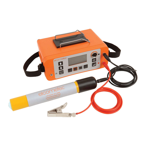
Figure 1. Elcometer 331 Concrete Covermeter (model BH shown) 1.3 Standards The Elcometer 331 Concrete Covermeter can be used in accordance with the following National and International Standards: BS1881:204, ASTM C876, DGZfP:B2, DGZfP:B3, TR60, UN110174 1.4 Conventions in these instructions A simple menu structure helps you get the most from your Covermeter - see “The menus”... -
Page 8: The Power Supply
Covermeter. One battery pack is supplied with the Covermeter. To increase productivity on site, Elcometer recommends that you purchase a spare battery pack which can be charged while you are using your Covermeter. -
Page 9: Fitting Search Heads
ETTING STARTED 3. Plug the charger supplied into the mains supply. The LED indicator on the charger will glow orange. 4. Leave the gauge charging for at least 4 hours. The LED indicator changes colour from orange to green when charging is complete. 5. -
Page 10: Identifying Search Heads
ETTING STARTED Borehole probe - set to forward-looking operation Borehole probe - set to sideways-looking operation The Covermeter must be zeroed after a search head has been fitted and after changing between high-tensile and stainless modes - the display will show PLEASE ZERO and the ZERO softkey will flash to remind you. -
Page 11: Fitting Half-Cell Probes
ETTING STARTED 3.4 Fitting half-cell probes (This section applies to Elcometer 331 Model BH only) Connect the probe and cables as shown in Figure 5. The search head can be left connected to the gauge at the same time as the half-cell probe, however for ease of use it is recommended that the search head is removed and stored in the carry case. -
Page 12: The Controls
ETTING STARTED 3.5 The controls All functions of the Covermeter can be controlled using the keypad on the main unit. There are two types of keys on the keypad; fixed function keys and ‘soft’ keys (Figure 6).. Switches the Covermeter Scrolls up/down on or off through menus and... -
Page 13: Switching The Covermeter On And Off
ETTING STARTED 3.6 Switching the Covermeter on and off Note: Before switching the Covermeter on for the first time read “Selecting a language” on page 11. To switch the Covermeter on, press [ To switch the Covermeter off, press and hold [ ] for two seconds. - Page 14 The display includes a backlight which illuminates the display for 10 seconds after any key is pressed and during measurements. Switch the backlight on or off as required. Switching the Half-cell mode is not included on the Elcometer 331 Model B.
-
Page 15: Selecting A Language
Covermeter. Replacement earphones are available as an optional accessory - see “Accessories” on page 33. The data transfer cable is not included with Elcometer 331 Model B or BH. For ordering information, see “Accessories” on page 33. An RS232 to USB transfer cable is available which allows you to connect your Covermeter to a USB port on... -
Page 16: Zeroing The Covermeter
Note: When Backlight is on, the display is illuminated for approximately 30 seconds after any key is pressed and during measurements. Half-cell probes cannot be fitted to the Elcometer 331 Model B. ‘Instrument mode’ is not included on Elcometer Model B. - Page 17 PROBE INFORMATION ..Press Enter to display technical information about the search head CONTACT ....Press Enter to display Elcometer offices worldwide and (if programmed) Supplier contact details HELP .
-
Page 18: Locating Reinforcement Bars
• The Covermeter will start to emit a sound which will increase in pitch as the search head moves closer to the bar. • The signal strength indicator bar on the display will increase in length. m. ‘Instrument mode’ - available on Elcometer 331 Model BH only. -
Page 19: To Locate Two Layers Of Reinforcement Bars
OCATING REINFORCEMENT BARS • The depth of cover on the display will show a number. • The LED on the search head will start to glow. The search head is aligned directly over a reinforcement bar when: • The pitch of the sound is at its highest. •... -
Page 20: To Determine The Orientation Of A Reinforcement Bar
OCATING REINFORCEMENT BARS • The second scan locates the nearer (top) layer. First scan Second scan Figure 11. Scanning layers of bars of different size (This situation is typical of a nearer layer consisting of relatively thin tie-wires or stirrups, and the deeper layer consisting of much larger main structural bars.) 5.4 To determine the orientation of a reinforcement bar 1. -
Page 21: Surface Mapping
OCATING REINFORCEMENT BARS can see. A block of wood or plastic 20 mm to 45 mm thick can be held between the search head and the bars to simulate the depth of concrete cover. Start from the simplest situation, a single straight bar, and progress through parallel bars, lapped bars, and crossing bars. -
Page 22: Measuring Depth Of Cover
8. The reading of cover is continuously updated on the display in large digits. If you are satisfied that the search head is directly over the reinforcement bar, record the depth of cover reading and move on to the next bar. ‘Instrument mode’ - available on Elcometer 331 Model BH only. -
Page 23: Accuracy
EASURING DEPTH OF COVER 6.3 Accuracy The reading of cover will only be accurate if all the following conditions are satisfied: • The instrument has been zeroed. • The search head is over the centre-line of the bar. • The search head is parallel to the bar. •... -
Page 24: Selecting Bar Size
ELECTING BAR SIZE 7 SELECTING BAR SIZE The dimensions of reinforcement bars are stored within the Covermeter. The dimensions are grouped into four standard series; Metric, Imperial, ASTM/Canadian and Japanese. To select bar size, display the reading screen and press the BAR softkey to access Bar Size selection: •... -
Page 25: Measuring Half-Cell Potential
11. View the reading of half-cell potential on the display. 12. If you are satisfied with the reading, record the half-cell potential and then move on to the next measurement location. Half-cell mode is not included on the Elcometer 331 Model B. -
Page 26: Measuring Cell-To-Cell Rather Than Cell-To-Bar
DJUSTING SENSITIVITY Figure 14. Typical instrument configuration for half-cell measurements 8.3 Measuring cell-to-cell rather than cell-to-bar In some instances it will not be possible to make a direct connection to a reinforcing bar. In this situation it is common practice to use two half-cell probes connected to the inputs of the Covermeter. - Page 27 DJUSTING SENSITIVITY To improve audible resolution when locating closely spaced reinforcement bars it may be beneficial to reduce the sensitivity below the optimum level described in the previous paragraphs. It is also possible to reduce sensitivity deliberately so that bars of adequate cover are not indicated, but bars of shallower cover are.
-
Page 28: Measuring Welded Mesh And Joined Bars
EASURING WELDED MESH AND JOINED BARS 10 MEASURING WELDED MESH AND JOINED BARS The procedures for locating and measuring depth of cover of welded mesh and joined bars are similar to those for reinforcement bars as described in sections 5 and 6 (pages 14 to 19). This section highlights the additional factors which must be considered when measuring welded mesh or joined bars. -
Page 29: Search Heads
EARCH HEADS Ordinary strength signals Ordinary strength signals are obtained when the head is accurately aligned with the middle of a side. Only this type of signal is suitable for measuring depth of cover. Figure 17. Ordinary strength signals from middle of one side of a loop 11 SEARCH HEADS Four types of search head are available for your Covermeter;... - Page 30 EARCH HEADS Borehole Probe The Borehole Probe is used to locate reinforcement bars, tendon ducts and other metallic objects in the vicinity of holes drilled into concrete. The probe will also measure depth of cover over a limited range, making it ideal when attempting to drill through a structure without making contact with reinforcement bars or tendon ducts.
- Page 31 EARCH HEADS To scan for reinforcement bars or ducts in line with (in front of) the end of the borehole: Set the switch to the forward looking position and push the Borehole Probe into the drilled hole slowly. Figure 20. Scanning a borehole 11.1 Search head extension arm This optional accessory allows the operator simple access to areas normally requiring ladders or scaffolding.
-
Page 32: Half-Cell Probes
CELL PROBES 12 HALF-CELL PROBES (This section applies to Elcometer 331 Model BH only) Two types of half-cell probe are available for your Covermeter. The probes can be easily identified by colour: • Copper-Copper Sulphate (Cu-CuSO ): Yellow • Silver-Silver Chloride (Ag-AgCl): Blue 12.1 Wetting your probe... -
Page 33: Error Messages
Numerical error. LARGE If error persists contact Elcometer. CLOCK Internal error. Return to Elcometer*. LANGUAGE Software error. Return to Elcometer*. MEMORY * Contact Elcometer or your Elcometer Supplier to arrange return. Figure 21. Example error message - search head not connected... -
Page 34: Personalised Welcome Screen
Elcometer or your Elcometer supplier. The Covermeter does not contain any user-serviceable components. In the unlikely event of a fault, the Covermeter should be returned to your Elcometer supplier or directly to Elcometer. The warranty will be invalidated if the gauge has been opened. -
Page 35: Technical Data
Weight (including Deep head search head): 1.6 kg (3.5 lb) All performance figures have been obtained when using Elcometer reference rebars of standard diameter at room temperature. Accuracy figures for the deep cover search head are obtained once the operating temperature has stabilised (after 10 minutes continuous use of the search head). -
Page 36: Related Equipment
Battery life: Up to 32 hours continuous use without backlight. Up to 20 hours with backlight. 18 RELATED EQUIPMENT Elcometer produces a wide range of concrete and coatings inspection equipment. Users of the Elcometer 331 Concrete Covermeter may also benefit from the following Elcometer products: •... -
Page 37: Accessories
Your Covermeter is complete with all the items required to get started. The following optional accessories are available from Elcometer, or your Elcometer supplier. To place an order please quote the sales part number which follows the description of each accessory. -
Page 38: Index
Data transfer cable Deep Cover search head Illuminated Depth of cover Liquid Crystal Display Dimensions Locating Single layer of bars Two layers of bars Earphone Earphones Elcometer 331 Maintenance Features Mapping Overview Menu items Error messages ABOUT AUTO SWITCH OFF BACKLIGHT Features... - Page 39 NDEX LCD CONTRAST Muting MENU Standards RESET Storage SERIES Surface mapping SETUP Switching on/off UNITS ZERO Menus Weight Metric bar size Welcome screen Muting the sound Creating Welded mesh Narrow Pitch search head Zeroing the Covermeter On/off Opening screen Creating Orientation Over-range Data transfer cable...
Need help?
Do you have a question about the 331 Series and is the answer not in the manual?
Questions and answers