Table of Contents
Advertisement
Advertisement
Table of Contents

Related Manuals for Elcometer 355


Summary of Contents for Elcometer 355
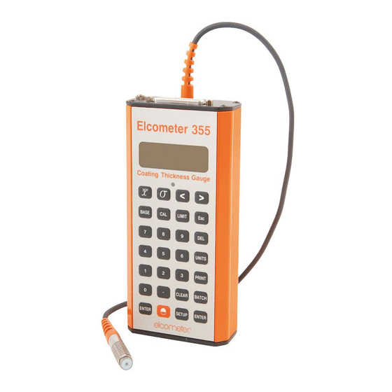
- Page 1 Elcometer 355 Coating Thickness Gauge Top Model Operating Instructions...
- Page 2 (electronic, mechanical, magnetic, optical, manual or otherwise) without the prior written permission of Elcometer Limited. A copy of this Instruction Manual is available for download on our Website via www.elcometer.com. Doc.No. TMA-0141 Issue 06...
-
Page 3: Table Of Contents
CONTENTS Section Page About your gauge ..............2 Getting started. -
Page 4: About Your Gauge
The Elcometer 355 Coating Thickness Gauge is a world beating product. With the purchase of this gauge you now have access to the worldwide service and support network of Elcometer. For more information visit our website at www.elcometer.com... - Page 5 For the IMO PSPC , the thickness of coatings should be recorded. Your Elcometer 355 can be used for this. NON-FERROUS (NF) ASTM D 1400, BS 3900 (C5), BS 5411 (3), BS 5599, DIN 50984, ISO 2360 supersedes BS 5411-3, ISO 2808-7D supersedes BS 3900-C5-6B, BS 5411-3, DIN 50984, ISO 2808-6B, ISO 2808-12, ASTM B244 (probes N1, N4).
- Page 6 Consult your Local Environmental Authority for further guidance. To maximise the benefits of your new Elcometer 355, please take some time to read these Operating Instructions. Do not hesitate to contact Elcometer or your Elcometer supplier if you have...
-
Page 7: Getting Started
2.2 FITTING BATTERIES Batteries are located under the cover at the rear of the gauge. (Elcometer 355 Top model shown) Fit three LR6 (AA), alkaline dry batteries, or rechargeable equivalent; take care to ensure correct battery polarity. - Page 8 2.3 CONNECTING A PROBE MODULE 1. Ensure the probe is suitable for the measurements to be made. 2. Switch off the gauge. 3. Open the cover at the back of the gauge. 4. Insert the probe module. 5. Replace the cover. 2.4 SWITCHING THE GAUGE ON AND OFF •...
- Page 9 A data output interface is located on the top of your gauge. 2.7 SELECTING A LANGUAGE The Elcometer 355 has a number of languages built-in.To select a language, see “Language function” on page 22. 2.8 CHANGING UNITS Your gauge can display coating thickness in µm (microns), mm, mil and thou.
-
Page 10: Taking A Reading
3 TAKING A READING Switch on the gauge. Place the probe on the surface to be measured. The reading may be inaccurate if the probe is not held as shown. The green LED will flash and a beep will sound when a valid reading within limits has been taken. -
Page 11: Calibration - Base And Cal
4 CALIBRATION - BASE AND CAL 1. Press [BASE] for low end calibration on a zero plate or low value foil and [CAL] for higher foil. If the password mode has been enabled (see “Password function” on page 20) then ‘- -’ is displayed and the password will have to be entered. -
Page 12: Batches And Memory
Note: If ‘base’ or ‘cal’ are used with regular values, the [BASE] or [CAL] keys may be pressed to recall the last value entered to the display in order to save re-entering the numeric data. [ENTER] is used to confirm the display value in memory. - Page 13 Immediate mode is designated as ‘BATCH 0’. Returning to immediate mode from batch mode clears all previous immediate mode data and starts at reading ‘0’. The time and day/month will always be stored at the time when the first reading is taken. In addition, if the time stamp mode is enabled (see “Date and time”...
- Page 14 5.3 CLEAR/DELETE BATCH DATA Data within a batch may be ‘cleared’ leaving the batch number, calibration and limits. Alternatively, the batch data and its associated number may be ‘deleted’. CLEARING CURRENT BATCH DATA Select the batch to be cleared - see “Selecting a batch” on page 10. Press [BATCH] and [CLEAR] (or simply press [CLEAR] to go straight to the alternating displays further on): Press [ENTER] and the display will alternate between ‘Clr’...
- Page 15 Press [ENTER] and the display will alternate between ‘dEL’ and ‘batch no’ as shown (batch number 14 in this example). Press [ENTER] to delete the batch or [Esc] to cancel the operation. CLEARING DEFINED BATCH DATA Press [BATCH] and [CLEAR]: Enter the ‘batch number’...
- Page 16 Enter the ‘batch number’ and then press [ENTER]; the display will alternate between ‘dEL’ and ‘batch no’ as shown (batch number 14 in this example). Press [ENTER] to delete the batch or [Esc] to cancel the operation. CLEARING ALL BATCHES This function is only available in immediate mode.
-
Page 17: Limits
Press [ENTER]; the display will alternate between ‘dEL’ and ‘ALL?’. Press [ENTER] to delete all batches or [Esc] to cancel the operation. 6 LIMITS If limits are set and a reading is taken which is outside the limits, the red LED will show and a longer beep will be given (1 second instead of 0.5 seconds). -
Page 18: Setup
Setting the reasonable limit to 99% will switch the reasonable limit function off. When a reasonable limit is reached for a reading value, the reading display will flash, the red LED will flash and the beep will sound a number of times. This prompts the user to accept the reading by pressing [ENTER] or reject the reading by pressing [DEL] (as for deletion of last reading). - Page 19 Continue stepping through the Printer SetUp Menu by using [>]. Press [ENTER] at the required option and use [<] and [>] to select within that option ([Esc] cancels the operation): End of line character is Cr or CrLF. Selects 80 or 42 column printing (42 col. for Elcometer Portable Printer).
- Page 20 Page length 0-100 lines (0 for continuous printing). 0-10 spaces of indentation from left (not available with 42 column printer). Type of report: Full or PArt (no readings). 7.2 DATE AND TIME When setting the date and time, the display flashes a 2 digit pair for day, month, hours or minutes. These may be adjusted up or down by using [<] and [>] respectively.
- Page 21 M:d for Month:Day (USA) Press [ENTER] or [Esc] to return to the ‘Coun’ display. Continue stepping through the time and date functions by using [>]. Press [ENTER] at the required option and use [<] and [>] to select within that option ([Esc] cancels the operation): Set day/month and year).
- Page 22 7.3 BEEPER FUNCTION Having pressed [SETUP], use [<] or [>] to select: Press [ENTER], and set beeper volume level using [<] or [>] (1 - 4 or 0 for none). Press [ENTER] to return to the ‘bEEP’ display or [Esc] to cancel the operation. 7.4 PASSWORD FUNCTION Having pressed [SETUP], use [<] or [>] to select: Password Function...
- Page 23 180 units. All batteries need to be replaced at readings of approximately 145. Note that Elcometer supplied rechargeable batteries should give a life of 1hr. between a flashing and a constant battery symbol, but alkaline batteries should last for a number of...
- Page 24 Press any operations key to return to the ‘bAtt’ display. 7.7 BACKLIGHT FUNCTION Having pressed [SETUP], use [<] or [>] to select: Backlight Enable/Disable. Press [ENTER] and use [<] and [>] to toggle between: on - Ensures the backlight is on at all times when required, but timed to maximise battery life. oFF - The backlight will be off at all times except for power up display test.
- Page 25 Swedish Danish Press [SETUP], [ENTER] or [Esc] to return to the ‘LAn’ display. 7.9 REASONABLE LIMITS FUNCTION Reasonable limits can be set between 0% and 99% of the range between the high and low limits, and apply above the high limit and below the low limit. For example, if the low limit is 100 µm and the high limit is 150 µm, the range is (150 - 100) = 50 µm.
- Page 26 Press [ENTER] to se the correct value (or [Esc] to cancel the operation). Press [SETUP] or [Esc] to return to the menu. 7.10 DATA COLLECTION/STATISTICAL FUNCTIONS After pressing [SETUP], Function No 10 (SEL) will be displayed: Select normal, averaging or counted average mode and their associated setups. For a description of average and counted average, see “Statistics”...
- Page 27 7.11 SETUP CHART...
-
Page 28: Statistics
8 STATISTICS These modes operate within batches and can be selected from the setup menu - see “Data collection/Statistical functions” on page 24. There are 3 modes available: 8.1 STATISTICS MODE The stats keys [ ], [σ], [<] and [>] will display (for 1 second or for as long as the key is pressed) mean, standard deviation, lowest and highest readings whether in immediate or batch (statistics) mode. - Page 29 8.3 COUNTED AVERAGE MODE The user predetermines how many readings should be taken to produce the average. This number is set within the SEL mode of Setup. As readings are taken, the reading number display shows ‘n’ and the number of readings taken so far. The ] symbol indicates that the main display is a true average.
-
Page 30: Transferring Readings To A Computer
• ElcoMaster Data Conversion Software. This software converts existing measurement data to ElcoMaster format. The following types of measurement data can be converted; Elcometer EDCS Win, EDCS Plus and EDCS. All this software can also be downloaded from the Elcometer website www.elcometer.com 9.1 TRANSFERRING USING A PC CABLE... -
Page 31: Printing
The setup mode may be used to select either the baud rate for serial printers or the parallel output printing mode. If the Elcometer portable mini printer is being used, the 42 column mode should be selected with the 8042 sub-function within the Prnt function of setup - see “Printer setup functions” on page 17. - Page 32 [ENTER] to print. Press [ENTER] to print all N batches* in the order in which they were used. Press [ENTER] to select specific transfer mode which may be used to transfer data to Elcometer’s ElcoMaster™ Software or to other data collectors.
- Page 33 Type in the required sub-function number. 70 - ‘Cont’ mode off 71 - Not available Sub-functions 72 to 76 (incl.) mimic print functions 2 to 6 shown previously. Press [SETUP] or [Esc] to return to the ‘trAn’ display. Continue with [>] to view Press [ENTER] to print out a ‘directory’...
- Page 34 Press [ENTER] to show all display segments and show the backlight is working. Press [ENTER], [Esc] or [SETUP] to end. Press [ENTER] to turn the Elcometer 355 off, or [Esc] or [SETUP] to return to the ‘SoFt’ display. Note: The batch symbol may be displayed if the instrument is in batch mode when the [PRINT] key is pressed.
-
Page 35: Fault Finding / Error Codes
11 FAULT FINDING / ERROR CODES To cancel any error code press [ENTER] or [Esc]: Code Explanation Calibration has been lost. Cal difference error is too large/small. A base value with too great a difference to that currently stored. Cal was attempted with too large a value. Base was attempted with too large a value. - Page 36 Code Explanation No readings were taken before trying to enter a base or cal factor. Limits cannot be changed in a batch with readings. Batch number entered cannot be found or Selected batch type not available. The probe module currently used is different to when this batch was created. The probe module is not responding or is not plugged in.
-
Page 37: Storage
If you return your Elcometer 355 for any reason, please describe why as fully as possible. Make sure that you include any probe modules that are associated with the condition, as most faults are associated with the consumable item (the probe) and an alternative module may allow further use of your gauge. -
Page 38: Accessories
The gauge does not contain any user-serviceable components. In the unlikely event of a fault, the gauge should be returned to your local Elcometer supplier or directly to Elcometer. The warranty will be invalidated if the gauge has been opened. - Page 39 14.1 PROBE MODULES Elcometer's unique Probe Modules allow versatile application of the Elcometer 355 Coating Thickness Gauges. Probe Modules can be freely interchanged as required on both ferrous (F) and non-ferrous (NF) metal substrates. Most Probe Modules are capable of an accuracy of ±1% of the reading on a variety of coatings and surfaces.
- Page 40 Probe type Part number Range Accuracy Resolution in range F5 (Rebar) T35511962 0 µm to 800 µm ±1% or ±2 µm 1 µm 0 µm to 800 µm 0 mils to 32 mils ±1% or ±0.08 mil 0.1 mils 0 mils to 32 mils F6 Standard T35511964 0 mm to 25 mm...
- Page 41 14.3 Precision hand grip The Elcometer 355 is supplied with a precision hand grip for use with the F1, F2 and N1 standard style probes. The grip is designed to help control the placement of the probe on surfaces in a repeatable way so...
- Page 42 14.8 Headphones/earpiece The Elcometer 355 has a 3.5mm jack socket fitted to the top end plate next to the 25 way D socket. This may be used with an earpiece with volume control (Part No. T35512220) or with headphones (Part No.
-
Page 43: Technical Specification
NiMH 20 hours minimum 16 RELATED EQUIPMENT Elcometer produces a wide range of coating thickness gauges and associated paint inspection equipment. Users of the Elcometer 355 may also benefit from the following Elcometer products: • Elcometer 550 Uncured Powder Thickness Gauges •... -
Page 44: Tutorial
This tutorial is intended to demonstrate the features of the Elcometer 355 Standard instrument and is designed to work with an F1 module fitted to an unused Elcometer 355. If other modules are used, or if information is stored from previous operations, the response of the instrument to the commands below may be different. - Page 45 Press [0], [ENTER] and the display will show: 17.3 Display some Statistics Take a set of up to five readings on a foil on a mild steel surface. (e.g. 935 microns). The number of readings increments in the top left hand corner as each reading is displayed. The last reading is held on the display.
- Page 46 17.5 Set CALibration and BASE Values Ensure the display shows ‘µm’. Press [CAL] and the display will show: Take a set of readings on a known value of foil on a steel substrate. The display will show the running mean for the set of readings. Modify the reading to be the actual value of the foil using the [>] or [<] and press [ENTER].
- Page 47 Now press [5] and [6]. The display will show: Press [CLEAR] to remove the batch number from the display. Press [1] [2] [3] and [ENTER] to create batch 123. Take readings into batch 123 and use [DEL] to delete the last reading. Note how the readings and value displays update.
- Page 48 17.10 To clear a specific batch Select the batch number (in this example, batch number 14) and press [CLEAR]: Press [ENTER] and the display will alternate between ‘Clr’ and ‘batch no’ as shown. alternating with Press [ENTER] to clear the selected batch (i.e. remove all readings) and return to the readings mode, or press [Esc] to cancel the operation.
- Page 49 17.12 To set limits Press [LIMIT] and the display shows: Press [<] to display current low (Lo) limit. The low limit software default values for all modules depends on the module, but will be a negative number. Enter a limit close to, but below the foil value being used and then press [ENTER].
- Page 50 Press [ENTER] to select the printer setup, and the display will show: Press [>] to step through the baud rate selections to: This selects 80 column format (A4) or 42 column format (Elcometer Portable Printer). Press [ENTER]. [<] and [>] will toggle between 80 and 42. Select 42 and press [ENTER].
- Page 51 Press [>] to step through to Password Select option: Press [ENTER] to display: Enter ‘0000’ (default password) to show: [<] or [>] will toggle between: and: not uSE = Password protection not activated. uSE = Password protection activated. Press [ENTER] and use [>] to step through to backlight option: Pressing [ENTER] displays current status - ‘oFF’...
- Page 52 Note: Counted average and average modes only function within a batch. Take some readings (at least 20) and note the effect of the counted average. Connect to a printer (use the Elcometer portable printer) and print the batch by pressing [PRINT] [2] and ‘batch number’ followed by [ENTER].
-
Page 53: Quick Reference Guide
18 QUICK REFERENCE GUIDE Switch on [ENTER] Enter data or batch mode / Switch off - hold key down Display mean [σ] Display standard deviation [<] Display lowest reading [>] Display highest reading [BASE] Set lowest calibration point [CAL] Set highest calibration point [LIMIT] Set high and low limits [Esc]... - Page 54 Calibration In the following section [n] or [n.n] is a number. [BASE] Select mode [CAL] [0], [n.n] Enter value [n.n] [BASE] Select previous value [CAL] [ENTER] [ENTER] Setting Limits [LIMIT] Select mode [<] or [>] High or low limit [n.n] [ENTER] Enter value (high or low) [n.n] [ENTER] Enter value (high or low)
- Page 55 Batch view [BATCH][.] To view current batch [BATCH] [n] [ENTER] [BATCH] [.] To view ‘n’ batch Batch Clear [BATCH] [CLEAR] [ENTER] [ENTER] To clear current batch [BATCH] [CLEAR] [n] [ENTER] [ENTER] To clear specified batch [BATCH] [CLEAR] [ENTER] [ENTER] To clear all batches (only when in immediate mode) Batch Delete [BATCH] [DEL] [ENTER] [ENTER] To delete current batch...
- Page 56 To delete all batches (only when in immediate mode) SetUp Mode [SETUP] [<] or [>] then [ENTER] To select required function or [SETUP] [n] To select required function Then use: [<] or [>] [ENTER] For sub-function or [n] [<] or [>] [ENTER] To change sub-function [SETUP] (+ [SETUP] or [Esc] as necessary) To exit...
- Page 57 Switch Instrument Off Hold down [ENTER] for more than 3 seconds Note: The Elcometer 355 will automatically switch off after 60 seconds (User selectable between 1 and 30 minutes - see “Date and time” on page 18).
Need help?
Do you have a question about the 355 and is the answer not in the manual?
Questions and answers