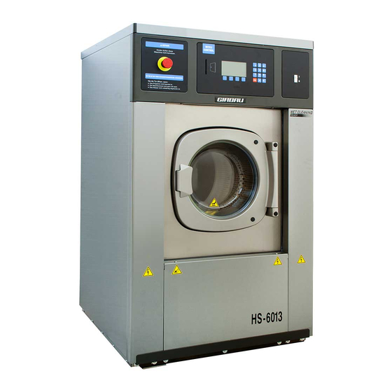
GIRBAU HS-6013 Installation Instructions Manual
Hide thumbs
Also See for HS-6013:
- Operation instructions manual (87 pages) ,
- Installation instructions manual (24 pages) ,
- Operating instructions manual (50 pages)
Table of Contents
Advertisement
Installation Instruction Manual
HS-6013/HS-6017/HS-6023/HS-6024
EH030/EH040/EH055/EH060
GIRBAU, SA
Crta de Manlleu, km. 1
08500 VIC (Barcelona) • SPAIN
National sales:
T.(+ 34) 902 300 359
comercial@girbau.es
International sales:
T.(+ 34) 938 862 219
sales@girbau.es
Service:
T.(+ 34) 902 300 357
sat@girbau.es
www.girbau.es
For USA and CANADA:
CONTINENTAL GIRBAU Inc.
2500 State Road 44
WI 54904 Oshkosh • USA
Tel. 1(920) 231-8222
info@continentalgirbau.com
www.continentalgirbau.com
washers
for
For more information and pricing, contact:
100 Melrose Avenue
Cherry Hill, NJ 08003
EN
Installation
HS-6013/17/23/24
EH030/040/055/060
Phone 800.223.1376
www.equipmentmarketers.net
info@eqpmark.com
Cod.nº 429043
Rev. 15/1215
Advertisement
Table of Contents

Related Manuals for GIRBAU HS-6013


Summary of Contents for GIRBAU HS-6013
- Page 1 100 Melrose Avenue sales@girbau.es info@eqpmark.com Cherry Hill, NJ 08003 Service: T.(+ 34) 902 300 357 sat@girbau.es www.girbau.es For USA and CANADA: CONTINENTAL GIRBAU Inc. Installation 2500 State Road 44 WI 54904 Oshkosh • USA HS-6013/17/23/24 Tel. 1(920) 231-8222 info@continentalgirbau.com EH030/040/055/060 www.continentalgirbau.com Cod.nº...
- Page 2 Model From serial # HS-6013 2,110,001 EH030 1,460,001 HS-6017 2,120,001 EH040 1,470,001 HS-6023 2,140,001 EH055 1,490,001 HS-6024 2,390,001 EH060 2,400,001 Cod.nº 429043 Rev. 15/1215...
-
Page 3: Table Of Contents
2.4. Washer location Conditions........................21 2.5. Installing more than one washer ......................23 2.6. Removal of shipping braces ........................24 2.6.1. HS-6013, HS-6017, HS-6024, EH030, EH040, EH060 models ............ 24 2.6.2. HS-6023, EH055 models ....................... 25 3. INSTALLATION ............................26 3.1. - Page 4 1. The actions described in these instructions are strictly reserved for contractually AUTHORISED TECHNICAL SERVICES (ATS) and personnel who have successfully completed training by Girbau 2. The company responsible for the Authorised Technical Service accepts full liability for the work done and any possible consequences that may derive from it.
- Page 5 Safety instructions Before beginning any procedure on machines equipped with an inverter or equipment with capacitative loads, wait for at least five minutes (10 minutes on equipment with a power rating greater than 25 kW) after the electrical disconnection, to eliminate risk of residual voltage. Close and mechanically lock the manual WATER, GAS, STEAM, THERMAL OIL, COMPRESSED AIR, etc.
-
Page 6: Safety Instructions
Safety instructions SYMBOLS USED IN MACHINE LABELLING Electrical risk High temperature risk Protective guard for elements carrying Handle with caution. an electric current. Use adequate protection. Risk of inhaling harmful or irritant Mechanical risk vapours Protective guard for moving parts. Keep the doors/covers closed. -
Page 7: Technical Specifications
Technical specifications 1. TECHNICAL SPECIFICATIONS 1.1. Tools needed for installation HS-6013; HS-6017; EH030; EH040 Shipping restraints ......open end wrench 11/16 inch. (17mm) Shipping restraints ......tubular wrench 11/16 inch. (17mm) HS-6023; HS-6024; EH055; EH060 Shipping restraints ......open end wrench ¾ inch. (19mm) ... -
Page 8: Declaration Of Conformity
Technical specifications 1.3. Declaration of conformity HS-6013 model EC DECLARATION OF CONFORMITY Manufacturer: GIRBAU S.A. Address: Ctra. de Manlleu, km 1, 08500 Vic, Barcelona, SPAIN Identification of the machine Generic denomination: Washer extractor Function: Washing in a water bath and extracting textiles... - Page 9 Technical specifications HS-6023 model EC DECLARATION OF CONFORMITY Manufacturer: GIRBAU S.A. Address: Ctra. de Manlleu, km 1, 08500 Vic, Barcelona, SPAIN Identification of the machine Generic denomination: Washer extractor Function: Washing in a water bath and extracting textiles Type: Front loading...
- Page 10 Technical specifications HS-6024 model EC DECLARATION OF CONFORMITY Manufacturer: GIRBAU S.A. Address: Ctra. de Manlleu, km 1, 08500 Vic, Barcelona, SPAIN Identification of the machine Generic denomination: Washer extractor Function: Washing in a water bath and extracting textiles Type: Front loading...
-
Page 11: Installation Specifications
Technical specifications 1.4. Installation specifications General specifications HS-6013 HS-6017 HS-6023 HS-6024 UNITS EH030 EH040 EH055 EH060 DRUM VOLUME dm3 (cu. ft) 126 (4.4) 173 (6.1) 228 (8.1) 239 (8.4) DRY LINEN CAPACITY kg 1/10 (lbs.) 12.6 (28) 17.3 (38) 22.8 (50.3) 23.9 (52.7) - Page 12 Technical specifications Legend CONNECTIONS DIMENSIONS (Figures 1, 2) Water supply Height from the machine base Drain Distance from the centre of symmetry of the unit Electrical connection inlet Depth Electrical connection inlet external dosing Height to door bottom Product inlets external dosing Gravity centre (GC) Steam inlet connection Vending...
-
Page 13: Connection Table Explanation
Technical specifications Environment and positioning conditions MAXIMUM TEMPERATURE ºC (ºF) +41 (+104) MINIMUM TEMPERATURE ºC (ºF) +5 (+40) LIGHTING VENTING OPENING (sq.ft.) 300 (0.4) MAXIMUM RELATIVE HUMIDITY WORKING AREA mm (in) 1000 (39.4) REAR MAINTENANCE AREA (*3) mm (in) 500 (19.7) *3. -
Page 14: Electrical Requirements
Technical specifications 1.6. Electrical requirements Check table explanation in section 1.5. In brackets: USA / CANADA specific values HS-6013 / EH030 TOTAL TOTAL SWITCH CONDUCTOR HEATING (*1) POWER CONSUMP. CURRENT (*2) VOLTAGE (AWG) 200V H / V 0.87 1.5 x 2 + 1ph + N red. - Page 15 Technical specifications Check table explanation in section 1.5. In brackets: USA / CANADA specific values HS-6017 / EH040 TOTAL TOTAL SWITCH CONDUCTOR HEATING (*1) POWER CONSUMP. CURRENT (*2) VOLTAGE (AWG) 200V H / V 1.5 x 2 + 1ph + N red.
- Page 16 Technical specifications Check table explanation in section 1.5. In brackets: USA / CANADA specific values HS-6023 / EH055 3Ph TOTAL TOTAL SWITCH CONDUCTOR HEATING (*1) POWER CONSUMP. CURRENT (*2) VOLTAGE (AWG) H / V 1.75 1.5 x 3 + 200V red.
- Page 17 Technical specifications Check table explanation in section 1.5. In brackets: USA / CANADA specific values HS-6023 / EH055 1Ph TOTAL TOTAL SWITCH CONDUCTOR HEATING (*1) POWER CONSUMP. CURRENT (*2) VOLTAGE (AWG) 200V 1ph + N H / V 1.75 2.5 x 2 + 208V 1.75 2.5 x 2 +...
- Page 18 Technical specifications Check table explanation in section 1.5. In brackets: USA / CANADA specific values HS-6024 / EH060 3Ph TOTAL TOTAL SWITCH CONDUCTOR HEATING (*1) POWER CONSUMP. CURRENT (*2) VOLTAGE (AWG) H / V 1.88 2.5 x 3 + 200V red.
- Page 19 Technical specifications Check table explanation in section 1.5. In brackets: USA / CANADA specific values Connection to power supply Iequ=16A Rsce=250 in accordance with UNE EN 61000-3-12:2012 Z min : (0.165+j0.109) Ohm EN 61000-3-11:2000 HS-6024 / EH060 1Ph TOTAL TOTAL SWITCH CONDUCTOR HEATING (*1)
-
Page 20: Receipt, Transport And Location
Transport and location 2. RECEIPT, TRANSPORT AND LOCATION 2.1. Receipt The following should be checked on accepting delivery of the washer: Check that the product has not suffered any damage in transit. (Any damage caused in this way will not be attributable to the manufacturer, and the appropriate claim should be made against the party responsible for transporting the product.) ... -
Page 21: Safety Door Unlock (Hs-6023, Hs-6024, Eh055, Eh060 Models Only)
Transport and location 2.3. Safety door unlock (HS-6023, HS-6024, EH055, EH060 models only) To open the door in case of power failure, completely insert a rod of a diameter of 0.2 in (3 mm) and an approximate length of 4 inches (100 mm) into the bottom side of the safety lock cover, and at the same time turn the knob downwards. - Page 22 WASHER GROUND MUST GROUND THESE SURFACES. HS-6013, HS-6017, EH030; EH040 models. To improve the ergonomics of loading and unloading operations, the washing machine can be installed on metal pedestals designed for this purpose (Fig. 2.3). Check the characteristics of this product with the manufacturer or the authorized distributors.
-
Page 23: Installing More Than One Washer
Transport and location 2.5. Installing more than one washer If the installation calls for more than one washer, align them with each other. The minimum distance between adjacent machines and the user and maintenance areas (values I, S and T of Figure 2.4) are specified on the table below. -
Page 24: Removal Of Shipping Braces
INCOMPLIANCE WITH THIS PRECAUTION MAY CAUSE SERIOUS PHYSICAL DAMAGES TO PEOPLE AND IRREPARABLE DAMAGES TO THE WASHER. THE WARRANTY DOES NOT COVER THIS INCIDENCE. 2.6.1. HS-6013, HS-6017, HS-6024, EH030, EH040, EH060 models Steps to follow (Fig. 2.5 and 2.6). ... -
Page 25: Hs-6023, Eh055 Models
Transport and location 2.6.2. HS-6023, EH055 models Remove the screws (Fig.2.7/A) holding the lower front cover and loosen the three screws (Fig. 2.7/B) holding the base of the chassis. Separate the rubber profile (Fig. 2.7/C) at the two small side guards and remove the front cover (Fig. -
Page 26: Installation
Installation 3. INSTALLATION ALL CONNECTIONS FOR ELECTRICAL POWER AND PLUMBING MUST COMPLY WITH THE STATUTORY SAFETY STANDARDS APPLICABLE TO EACH COUNTRY, AND BE MADE BY AUTHORISED INSTALLATION CONTRACTORS ONLY. ALL THE WASHER CONNECTIONS MUST BE CARRIED OUT BY THE AUTHORIZED TECHNICAL SERVICE. - Page 27 Installation Direct connection of the washer drain to the manifold (Fig. 3.3) Facilities preferring this option to the open box option (recommended option) must respect the following precautions: Provide next to the connection point of each machine to the manifold, with a manifold ventilation outlet A reaching the outside, set at a height of 40 in (1000 mm) and of a diameter of 2 in (50 mm).
-
Page 28: Water Supply
Installation 3.2. Water supply IMPORTANT! The local or national regulations concerning the water supply system in the country where the washing machine is installed must be followed. Hoses and pipes should be flushed through before being connected to the machine. Install at each water supply and in an accessible location, a mechanically interlocked water valve. -
Page 29: Electrical Connection
CONNECTED TO THE GROUND INSTALLATION WITH A CONDUCTOR CONNECTED TO THE EQUIPMENT GROUNDING TERMINAL. HS-6013, HS-6017, EH030 AND EH040 GIRBAU WASHING MACHINES ARE DESIGNED TO OPERATE IN SINGLE-PHASE AND THREE-PHASE LINES. MODELS OF VOLTAGE BETWEEN 380 AND 415 V REQUIRE IN ADDITION A CONNECTION TO THE NEUTRAL WIRE. -
Page 30: Machine Electrical Connection
Installation Safety switch. Install an Automatic on/off Switch, outside the washer, with individual protection for each machine. Characteristics: number of poles and intensity: consult ELECTRICAL CONNECTION table (section 1.5) C type with top opening greater than 0.12 in (3 mm) ... -
Page 31: Steam Connection
Installation 3.4. Steam connection In some models the body of the steam solenoid valve and the filter are shipped inside the drum of the washing machine, separate from the electrical wiring system. The coil is connected to the end of the electrical installation. In other models, the assembly solenoid valve and filter are supplied connected to the electrical wiring system. -
Page 32: External Dosing Electrical Connection
Installation 3.5.1. External dosing electrical connection 3.5.1.a. Steps prior to connection: Disconnect and mechanically lock the external automatic switch. Open the machine’s terminal box. On the entry hole of the external dosing electrical supply (Ed identified in figure 2) install a lock mechanism (not supplied with the washer) to fasten the cable or cable pipe protector, depending on the cable and pipe protector used. - Page 33 Installation 3.5.1.d. Dosing equipment connection. RELAY CONTACTS POWERED FROM THE WASHER CONTROL CIRCUIT. (Fig. 3.10) IMPORTANT This connection allows for the maximum strength at each of the 50mA outputs. Higher consumption can prevent the washer from functioning correctly. This connection can aggravate any problems produced by a fault in the grounding connection, both of the washer itself and of the external dosing equipment.
-
Page 34: External Dosing Hoses Connection
Installation 3.5.2. External dosing hoses connection The external dosing inlets are perforated and protected by a tube cap. Refer dimensions dosing inlets diameter INSTALLATION SPECS, section 1.4. To connect the product cables: Locate the dosing inlets in the back of the machine. ... -
Page 35: External Signal. Connection
Installation 3.6. External signal. Connection CAUTION! Option available in Inteli Control models only. To be able to use this option, the washing machine must be fitted with the A6 board, duly installed and activated in the SETUP menu. External signal. It is possible to use an order from the washing machine control to issue an end of program or alarm warning. -
Page 36: Emergency Stop In Coin-Op Installations
Installation 3.8. Emergency stop in coin-op installations IN ACCORDANCE WITH SAFETY REQUIREMENTS FOR INDUSTRIAL MACHINERY STANDARD (UNE- EN ISO 10472-1,5-2) AND OTHER SAFETY REQUIREMENTS, THE LAUNDRY OWNER / USER IS RESPONSIBLE FOR INSTALLING A REMOTE LOCATED EMERGENCY STOP DEVICE, CONNECTED TO EACH MACHINE.
Need help?
Do you have a question about the HS-6013 and is the answer not in the manual?
Questions and answers