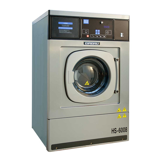
GIRBAU HS-6008 Installation Instructions And Information Manual
Hide thumbs
Also See for HS-6008:
- Installation instructions manual (30 pages) ,
- Operation instructions manual (25 pages) ,
- Installation manual (24 pages)
Table of Contents
Advertisement
Installation
GIRBAU, SA
Crta de Manlleu, km. 1 1
08500 VIC (Barcelona) SPAIN
National sales:
Tel.(+ 34) 902 300 359
comercial@girbau.es
International sales:
Tel.(+ 34) 938 862 219
sales@girbau.es
Service:
Tel.(+ 34) 902 300 357
sat@girbau.es
For USA and CANADA:
CONTINENTAL GIRBAU Inc.
2500 State Road 44
WI 54904 Oshkosh USA
Tel. 1(920) 231-8222
info@continentalgirbau.com
www.continentalgirbau.com
instructions for washers
HS-6008 / EH020
EN
Installation
HS-6008
EH020
Model
From serial #
HS-6008
EH020
2,080,001
1,430,001
Cod. 428938
Rev. 05/0717
Advertisement
Table of Contents

Related Manuals for GIRBAU HS-6008


Summary of Contents for GIRBAU HS-6008
- Page 1 Model From serial # HS-6008 2,080,001 EH020 1,430,001 instructions for washers Installation HS-6008 / EH020 GIRBAU, SA Crta de Manlleu, km. 1 1 08500 VIC (Barcelona) SPAIN National sales: Tel.(+ 34) 902 300 359 comercial@girbau.es International sales: Tel.(+ 34) 938 862 219 sales@girbau.es...
-
Page 2: Table Of Contents
Contents CONTENTS SAFETY INSTRUCTIONS ..........................3 1. TECHNICAL SPECIFICATIONS ........................6 Tools needed for installation ........................6 Accessories in machine ........................... 6 EC Declaration of conformity........................7 Installation specifications ..........................8 Electrical requirements .......................... 10 Connection table explanation ........................ 11 2. -
Page 3: Safety Instructions
1. The actions described in these instructions are strictly reserved for contractually AUTHORISED TECHNICAL SERVICES (ATS) and personnel who have successfully completed training by Girbau 2. The company responsible for the Authorised Technical Service accepts full liability for the work done and any possible consequences that may derive from it. - Page 4 Safety instructions capacitative loads, wait for at least five minutes (10 minutes on equipment with a power rating greater than 25 kW) after the electrical disconnection, to eliminate risk of residual voltage. Close and mechanically lock the manual WATER, GAS, STEAM, THERMAL OIL, COMPRESSED AIR, etc.
- Page 5 Safety instructions HAZARD AND PROHIBITION SYMBOLS USED IN MACHINE LABELLING Electrical risk High temperature risk Protection guard electric Operate with caution. components. Use appropriate protections. Risk of inhaling harmful or irritant Mechanical risk vapours Protection guard for moving parts. Keep the doors/covers closed. Use appropriate protections.
-
Page 6: Technical Specifications
Technical specifications 1. TECHNICAL SPECIFICATIONS Tools needed for installation ......Shipping restraints open end wrench 1/2 in (13mm) ........Legs fixing open end wrench 11/16 in (17 mm) ...... Legs fixing and clamps nut driver 7 mm ... -
Page 7: Ec Declaration Of Conformity
Technical specifications EC Declaration of conformity EC DECLARATION OF CONFORMITY Manufacturer: GIRBAU S.A. Address: Ctra. de Manlleu, km 1, 08500 Vic, Barcelona, SPAIN Identification of the machine Generic denomination: Function: Type: Washer extractor Washing in a water bath and extracting textiles... -
Page 8: Installation Specifications
Technical specifications Installation specifications General specifications MODEL UNITS HS-6008 / EH020 DRY LINEN CAPACITY kg 1/10 (lbs.) 8 (17.7) r.p.m. 580 / 970 SPIN factor G 101 / 283 WASHING SPEED (max) r.p.m. STATIC FORCE TRANSMITTED kg (lbs.) 154 (340) DYNAMIC FORCE TRANSMITTED kg (lbs.) - Page 9 Technical specifications Environment and positioning conditions MAXIMUM TEMPERATURE ºC (ºF) +41 (+104) MINIMUM TEMPERATURE ºC (ºF) +5 (+40) LIGHTING VENTING OPENING (sq.ft.) 300 (0.4) MAXIMUM RELATIVE HUMIDITY WORKING AREA mm (in) 1000 (39.4) REAR MAINTENANCE AREA mm (in) 500 (19.7) Fig.
-
Page 10: Electrical Requirements
Technical specifications Electrical requirements Check table explanation in section 1.6. In brackets: USA / CANADA specific values TOTAL TOTAL SWITCH CONDUCTOR HEATING VOLTAGE POWER CONSUMP. CURRENT. (*2) (*1) (AWG) 1.5 x 2 + 120V 1Ph + N (15A mains outlet (supplied by the (0.8) (6.7) -
Page 11: Connection Table Explanation
Technical specifications Connection table explanation 1) HEATING 2) EXPLANATION OF CONNECTION VALUES Without heating Wire details in mm2 x B + N + Electric heating (USA/CANADA: wire details in AWG) x B + GND) Consult TOTAL ELECTRICAL POWER Wire number in the nameplate + N + Neutral wire... -
Page 12: Transport And Location
Transport and location 2. TRANSPORT AND LOCATION Transport of crated machines ALWAYS USE TRANSPORT METHODS WHICH ARE SUITABLE FOR THE WEIGHT AND VOLUME OF THE WASHER. CHECK THE VALUES ON THE PACKAGING AND THE INSTALLATION SPECS (section 1.4) of this manual. ... -
Page 13: Removal Of Shipping Braces
Transport and location Removal of shipping braces DO NOT REMOVE THE SHIPPING RESTRAINTS BEFORE PLACING THE WASHER IN ITS DEFINITIVE POSITION. NEVER START THE MACHINE UP WITHOUT FIRST REMOVING THE SHIPPING RESTRAINTS. INCOMPLIANCE WITH THIS PRECAUTION MAY CAUSE SERIOUS PHYSICAL DAMAGES TO PEOPLE AND IRREPARABLE DAMAGES TO THE WASHER. -
Page 14: Installation On A Very Irregular Floor
Transport and location Installation on a very irregular floor If the floor is very irregular and it requires SIGNIFICANT LEVEL CORRECTION, use the open washers for levelling. For this: Determine which of the legs should be shimmed for levelling the washing machine; raising the front or the rear part of the machine and place a wooden spacer of 200 mm (8 in) in height, under the machine to serve as a lift. -
Page 15: Installation
Installation 3. INSTALLATION ALL CONNECTIONS FOR ELECTRICAL POWER AND PLUMBING MUST COMPLY WITH THE STATUTORY SAFETY STANDARDS APPLICABLE TO EACH COUNTRY, AND BE MADE BY LICENSED INSTALLERS ONLY. Gravity drain Drain to the drain box. (Most recommended option) Build a drain box following the specifications indicated in the INSTALLATION SPECS, section 1.4. -
Page 16: Pump Drain
Installation Pump drain Assemble hose securing clamp to the rear cover (Fig. 13). Connect the drain hose at the machine outlet and secure with the corresponding clamp. Secure the drain hose to the rear cover with the securing clamp (Fig. 14). Fig. -
Page 17: Water Supply
Installation Water supply Hoses and pipes should be flushed through before being connected to the machine. Install at each water supply and in an accessible location, a mechanically interlocked water valve. Refer to technical specifications on the INSTALLATION SPECS, section 1.4. Arrangement of the hoses (Fig. - Page 18 Installation Assembling the connection couplings for AUSTRALIA IMPORTANT 20mm dual check valve supplied with machine must be installed on the cold water inlet to the machine. This valve is designed to prevent cross connection (back siphonage) and complies with AS/NZS Standard 2845.1 (Watermark).
-
Page 19: Electrical Connection. Permanently Connected Appliances
CONNECTED TO THE GROUND INSTALLATION WITH A CONDUCTOR CONNECTED TO THE EQUIPMENT GROUNDING TERMINAL. GIRBAU WASHING MACHINES HS-6008, EH020 ARE DESIGNED TO OPERATE IN SINGLE-PHASE AND THREE-PHASE LINES. MODELS OF VOLTAGE BETWEEN 380 AND 415 V REQUIRE IN ADDITION A CONNECTION TO THE NEUTRAL WIRE. -
Page 20: Machine Electrical Connection
Installation Circuit breaker. Install an earth-leakage protected circuit breaker. Characteristics: Installed in an easily accessible place. number of poles and intensity: consult ELECTRICAL CONNECTION table (section 1.5) A type. protected against pulse currents, harmonics, the presence of continuous components... (consult manufacturer specifications) Safety switch. -
Page 21: External Dosing (Option)
Installation External dosing (option) This machine can control external dispenser equipment by generating a signal able to activate the various inlets of the dispenser equipment. These signals are made by closing a relay contact between the COMMON terminal and the outputs of each one of the various terminals coinciding with the different dosing made by the washing programs. -
Page 22: Initial Start-Up
Installation Initial Start-up The washer must be put into service by an AUTHORIZED SERVICE TECHNICIAN. Before the initial STARTING, make sure that you accomplish the following points: Remove all packaging materials (Break them down in order to appropriately recycle them) ... -
Page 23: Wash Cycle Start-Up From An External Device To The Washing Machine
Installation Wash cycle start-up from an external device to the washing machine VERY IMPORTANT !!! Washing machine cycle start-up should only be started by voluntary activation using an actuating element designated for this purpose. For machines connected to a remote control start-up system (e.g. a central vending point, etc.), the control must be located so as to ensure that the operator may be absolutely certain that no person is exposed to any dangerous area of the washing machine (pursuant to Machine Directive 98/37/CE, Annex 1).
Need help?
Do you have a question about the HS-6008 and is the answer not in the manual?
Questions and answers