
Related Manuals for RED EPIC-M RED DRAGON (Carbon Fiber)


Summary of Contents for RED EPIC-M RED DRAGON (Carbon Fiber)
- Page 1 EPIC/SCARLET OPERATION GUIDE EPIC SCARLET RED DRAGON MYSTERIUM-X MONOCHROME V6.3 RED.COM...
-
Page 2: Table Of Contents
Safety Instructions Access the Advanced Menus Battery Storage and Handling Settings Menu Shipping Disclaimer Media Menu 1 RED Product Introduction Playback Menu Read Before You Shoot Power Menu R3D File Format and REDCODE HDRX Menu Shoot For Video and Stills... -
Page 3: 5 5 - 0 0 2 0 _V 6 .3 , R Ev - F
EPIC/SCARLET OPERATION GUIDE 9 Upgrade Camera Firmware Verify Current Camera Firmware Upgrade Camera Firmware 10 Camera System Maintenance BRAIN and Accessory Exterior Surfaces Clean the Camera Sensor or OLPF Clean EVF Screen Clean LCD Screens Water Damage Adjust Back Focus 11 Troubleshoot Your Camera Perform a Stress Test General Troubleshooting... -
Page 4: Disclaimer
While thought to be accurate, the information in this standards RSS 139 and RSS 210. Operation is subject to the following document is provided strictly “as is” and RED will not be held two conditions: (1) this device may not cause interference, and (2) this responsible for issues arising from typographical errors or user’s... - Page 5 Products with the CE marking comply with the EMC Directive AUSTRALIA AND NEW ZEALAND STATEMENTS (2004/108/EC) and the Low Voltage Directive (2006/95/EC) issued by RED declares that the radio equipment described in this document the Commission of the European Community. Compliance with these comply with the following international standards.
-
Page 6: Safety Instructions
DO RESPONSIBLE PARTY NOT use soaps, detergents, ammonia, alkaline cleaners, and RED Digital Cinema abrasive cleaning compounds or solvents. These substances may damage lens coatings and electronic circuitry. 34 Parker Maintain sufficient ventilation—DO NOT block any ventilation... - Page 7 WARNING: Danger of explosion if an incorrect Operating range: 0°C to 40°C (32°F to 104°F) battery is charged with the RED Charger or is Storage range: –20°C to 50°C (–4°F to 122°F) used to power the camera and accessories.
-
Page 8: Battery Storage And Handling
40% to 60%. If batteries will be stored for long periods of time, RED recommends that you check the charge level at least once DO NOT exceed the recharging temperature range of 0˚C to 40˚C every six (6) months, and recharge batteries to a capacity level of (32˚F to 104˚F). -
Page 9: Shipping Disclaimer
United States. REDVOLT, REDVOLT XL, and RED BRICK batteries are considered Dangerous Goods. Other products such as REDVOLT AA and RED Li 7.2V batteries may also be classified as Dangerous Goods when purchased in bulk. Applicable laws prohibit the shipping of batteries that are physically damaged. -
Page 10: Red Product Introduction
EPIC/SCARLET OPERATION GUIDE RED PRODUCT INTRODUCTION Figure: EPIC Camera and Accessories ® ® The EPIC and SCARLET cameras are part of the RED Digital Still and Motion Camera (DSMC ) system. The DSMC ® ® family includes EPIC, SCARLET , WEAPON , RED EPIC-W™, SCARLET-W, and RED RAVEN cameras. -
Page 11: Read Before You Shoot
EPIC/SCARLET OPERATION GUIDE READ BEFORE YOU SHOOT Read this operation guide carefully and in its entirety before assembling or operating your camera or other RED accessories. In addition to this document, RED offers the following operation guides for the camera system:... -
Page 12: Post Production With Redcine-X Pro
R3D files. RED TETHER, included in REDCINE-X PRO, allows you to record footage from your camera directly to a computer or an external drive. Using tethering bypasses the need to record to an SSD and offload to a computer later, saving you time. -
Page 13: Camera System Components
NOTE: Availability of components listed in this chapter is subject to change at any time. ADDITIONAL RESOURCES For more information on power and media, see the following guides, available at www.red.com/downloads: DSMC Power Operation Guide DSMC Media Operation Guide BRAIN Figure: EPIC BRAIN... -
Page 14: Media Modules
Firmware update in progress Status LED (REC) Both red flashing Firmware update error MEDIA MODULES This section describes the media modules. RED offers the following media modules: ITEM PART NUMBER DSMC 1.8" SSD Side Module 720-0013 DSMC 1.8" SSD Side Module (DRAGON) Carbon Fiber DSMC 1.8"... - Page 15 Rear SSD Module 720-0009 1. The DSMC 1.8" SSD Side Module (DRAGON) is only available with the purchase of a RED DRAGON sensor-based BRAIN. 2. Carbon fiber side SSD modules are only available with the purchase of a carbon fiber BRAIN.
-
Page 16: Rear Ssd Module
For more information, see the DSMC Media Operation Guide, available at www.red.com/downloads. C O PYR I G HT © 2 0 1 6 R ED.C O M , I NC 9 5 5 - 0 0 2 0 _V 6 .3 , R EV - F | 1 6... -
Page 17: Redmag And Red Mini-Mag Systems
1. To see the Model number, go to Menu > Media > Device. 2. The RED MINI-MAG 1TB can take up to 20 seconds to mount to a computer or a camera. C O PYR I G HT © 2 0 1 6 R ED.C O M , I NC... - Page 18 RED STATION REDMAG 2.5" 750-0007 1. These REDMAG 1.8" SSDs are no longer available for purchase at red.com, but are still supported by RED. 2. The REDMAG 1.8" SSD (240GB) requires that your camera is on firmware v5.1.44 or later.
-
Page 19: Adaptor Modules
WARNING: The Module Adaptor is NOT compatible with the +1 Adaptor Module. WARNING: The +1 Adaptor Module IS NOT compatible with the Module Adaptor. WARNING: DO NOT use the EVF/LCD port if a Pro I/O Module is connected to the camera. RED offers the following adaptor modules: ITEM PART NUMBER... - Page 20 3 Auxiliary 4-pin 0B Supplies unregulated (+) 11.5 to 17 V battery pass-through; Connect to 2-pin LEMO power out LEMO accessories with the RED 4-Pin to 2-Pin Adaptor Cable; Max sustained current is 2 A (PWR) ® 4 REDMOTE 8-point...
- Page 21 EPIC/SCARLET OPERATION GUIDE +1 ADAPTOR MODULE ACCESSORIES For more information, as well as a full list of EVF/LCD cables and other accessory cables, go to the RED Store www.red.com. Accessory Connector Type Connector Function Part Number 4-Pin To 2-Pin 4-pin 0B to 2-pin 0B...
-
Page 22: Power Modules
Power modules attach to a Module Adaptor or +1 Adaptor Module to provide the camera with flexible power options ® ® for REDVOLT , REDVOLT XL, and RED BRICK batteries. When used in combination with a DSMC AC Power Adaptor or DSMC Side Handle, you can hot-swap batteries without interrupting recording. RED offers the following power modules:... -
Page 23: Red Batteries And Chargers
These batteries provide long-term mobile power and attach to the camera via a power module or other RED accessory, such as the DSMC Side Handle. RED chargers replenish lost capacity for REDVOLT, REDVOLT XL, and RED BRICK batteries. -
Page 24: Other Modules
The Pro I/O Module offers the following features: Centralized ports that make it easy to manage connections and cables. LCD/EVF port that allows you to connect an additional RED LCD or EVF. Customizable triggers that interface with third-party GPIO and RS232 control devices using Pro I/O cables. - Page 25 For more information, see the REDCAST Module Operation Guide, available at www.red.com/downloads. C O PYR I G HT © 2 0 1 6 R ED.C O M , I NC 9 5 5 - 0 0 2 0 _V 6 .3 , R EV - F | 2 5...
-
Page 26: Displays And Electronic Viewfinders
2. Using this display with a DSMC2 camera requires a DSMC2 LEMO Adaptor A. 3. The RED Touch 7.0" LCD requires that your camera is on firmware v5.2.38 or later. For a full list of LCD and EVF user keys and default actions, go to "Default Key Functions"... - Page 27 LCD PRECAUTIONS WARNING: DO NOT use a RED display as a handle to lift or carry the camera. Damage to a RED display or other components of the camera system caused by using the display as a handle are not covered under warranty.
- Page 28 BOMB EVF FEATURES # Feature Description 1 EVF Custom digital video and power interconnection between the camera and RED EVF; Pinout not connector published 2 EVF Tally When enabled, the LED illuminates red when recording; For more information, go to "Indicator"...
- Page 29 WARNING: DO NOT point the DSMC2 RED EVF (OLED) eyepiece at direct sunlight. Continued exposure to direct sunlight may damage the EVF. Point the eyepiece away from sunlight when not in use. Damage to the DSMC2 RED EVF (OLED) caused by continued exposure to direct sunlight is not covered under warranty.
- Page 30 1 DSMC2 RED EVF The DSMC2 RED EVF Mount Mount 2 EVF connector Custom digital video and power interconnection between the EVF and other RED devices; Pinout not published; compatible with standard RED EVF/LCD LEMO cables 3 Key 1 Programmable key...
-
Page 31: Lemo Adaptors
(top), or the secondary (side) EVF/LCD port on the DSMC2 camera. When used along with the DSMC2 LEMO Adaptor B, this adaptor enables you to mount a DSMC2 RED Touch LCD away from the camera—to a NOGA arm or other stable mounting point. -
Page 32: Camera Control Modules
Bridge (REDLINK Development Kit) 720-0028 1. The RED Switchblade-M requires that your camera is on firmware v5.2.28 or later. Full functionality requires firmware v5.3 or later. 2. The REDLINK Bridge requires that your camera is on firmware v5.2.28 or later. - Page 33 EPIC/SCARLET OPERATION GUIDE DSMC SIDE HANDLE Figure: DSMC Side Handle The DSMC Side Handle provides programmable menu controls and a battery compartment that holds one (1) REDVOLT battery. The DSMC Side Handle LCD display shows camera parameter values and illuminates for operation in dark environments.
- Page 34 Figure: RED Switchblade-M The RED Switchblade-M is a low-profile and lightweight interface solution that mounts to the side of the camera. With a 1.7” OLED display and full navigation controls, the RED Switchblade-M grants full access to menus while optimizing the size and weight of y our camera configuration.
- Page 35 EPIC/SCARLET OPERATION GUIDE REDMOTE Figure: REDMOTE The REDMOTE is a remote camera control unit that attaches to the rear of the camera or rearmost expansion module. The REDMOTE may be detached from the camera or rearmost module and provide wireless remote control of the camera over the proprietary REDLINK protocol.
- Page 36 For more information, see the REDLINK Bridge Operation Guide, available at www.red.com/downloads. NOTE: The REDLINK Bridge requires camera firmware v5.2.8 or later. C O PYR I G HT © 2 0 1 6 R ED.C O M , I NC...
-
Page 37: Lens Mounts
T8 TORX driver. 2. The DSMC RED MOTION MOUNT requires that your camera is on firmware v5.1.14 or later. C O PYR I G HT © 2 0 1 6 R ED.C O M , I NC 9 5 5 - 0 0 2 0 _V 6 .3 , R EV - F | 3 7... -
Page 38: Interchangeable Olpfs
2. Monochrome OLPFs are for use with the DRAGON Monochrome sensor ONLY. RAILS, MOUNTS, TACTICAL GEAR, AND CABLES RED offers a wide variety of support gear, mounting platforms, cables, accessories, and other equipment. For more information, visit the RED Store at www.red.com/store. -
Page 39: Basic Operations
WARNING: While third-party batteries may be mechanically compatible with the camera system, the manufacturer is ® responsible for the performance and stability of third-party options, not RED . Damage to the camera system or third- party devices caused by using third-party power options is not covered under warranty. The camera may be unable to determine and display the voltage or remaining battery capacity of third-party power options. - Page 40 When multiple power sources are connected to the camera, power consumption is prioritized in this sequence: 1. DC power supply (DC IN connector) 2. Attached RED BRICK (Lowest state of charge first) 3. Battery module batteries (SEARAY connector; lowest state of charge first) 4.
-
Page 41: Power Consumption
Use a RED ONE DC Power Cable (P/N 790-0060) and 2B-to-1B Power Adaptor Cable (P/N 790-0138). Use a RED 2B-to-1B LEMO Power Cable (P/N 790-0556). RED BRICK: Requires a Backpack Quickplate or Battery Belt Clip (DSMC). Also supported by a RED Quickplate or RED Cradle using a 2B-to-1B Power Adaptor Cable. -
Page 42: Configure Your Camera
EPIC/SCARLET OPERATION GUIDE CONFIGURE YOUR CAMERA This section describes common options for configuring your camera system. DSMC SIDE HANDLE: INSTALL/REMOVE INSTALL THE DSMC SIDE HANDLE WARNING: Before installing or removing this item, you MUST turn off the camera. ® REQUIRED TOOLS: T10 TORX driver 1. - Page 43 3. Rotate the BRAIN side plate upwards to disengage the lip at the top of the side plate from the camera, and remove the BRAIN side plate. 4. Insert the lip on the RED Switchblade-M into the slot where the lip of the BRAIN side plate was installed. 5. Press the Switchblade-M down flush along the side of the camera.
- Page 44 EPIC/SCARLET OPERATION GUIDE MODULE ADAPTOR AND +1 ADAPTOR MODULE: INSTALL/REMOVE INSTALL THE MODULE ADAPTOR You must install an adaptor module on the back of the camera before you install a module. REQUIRED TOOLS: T20 TORX driver 1. Turn off the camera. 2.
- Page 45 EPIC/SCARLET OPERATION GUIDE 5. Fully tighten the four (4) screws in a cross pattern (“X” pattern) using a T20 TORX driver. Figure: Tighten Screws WARNING: DO NOT OVERTIGHTEN. REMOVE THE MODULE ADAPTOR REQUIRED TOOLS: T20 TORX driver 1. Turn off the camera. 2.
- Page 46 EPIC/SCARLET OPERATION GUIDE MODULES: ATTACH/REMOVE ATTACH A MODULE REQUIRED TOOLS: T20 TORX driver 1. Turn off the camera. 2. Insert the lip at the top of the module into the recess at the top of the adaptor module. Figure: Insert Module Lip 3.
- Page 47 EPIC/SCARLET OPERATION GUIDE REMOVE A MODULE REQUIRED TOOLS: T20 TORX driver 1. Turn off the camera. 2. Use a T20 TORX driver to turn the lock on the adaptor module counter-clockwise to the Unlock position. 3. Rotate the module upwards and away from the adaptor module to disengage. 4.
- Page 48 REQUIRED TOOLS: T8 TORX driver The hood scoop on some EPIC-X and EPIC-M models extends beyond the rear plane of the camera. RED offers shorter hood scoops so that you can attach an LCD or other accessory to the mounting locations on the top of the +1 Adaptor Module.
-
Page 49: Interchangeable Olpf System
EPIC/SCARLET OPERATION GUIDE INTERCHANGEABLE OLPF SYSTEM This section describes the process for swapping an interchangeable OLPF. WARNING: Read these instructions carefully and in their entirety before removing or installing an interchangeable OLPF. Damage caused to the OLPF module, camera, or sensor due to improper handling or use is not covered under warranty. - Page 50 EPIC/SCARLET OPERATION GUIDE 6. Remove the four (4) M2x0.4 x 4 mm OLPF module screws (P/N 600-0224) in a cross pattern (“X” pattern) using a T6 TORX driver. Figure: Remove OLPF Module Screws 7. Remove the OLPF module and place it in its protective case. Figure: Remove the OLPF Module C O PYR I G HT ©...
- Page 51 EPIC/SCARLET OPERATION GUIDE 8. Use an LED light to ensure that the optical cavity is clean and free from dust or debris. Figure: Ensure Optical Cavity Is Clean and Free of Debris 9. Ensure the new OLPF module is clean and free of debris. 10.
- Page 52 EPIC/SCARLET OPERATION GUIDE 14. Replace and loosely tighten the four (4) M4x0.7 x 8 mm lens mount screws in a cross pattern (“X” pattern) using a T20 TORX driver. DO NOT FULLY TIGHTEN. NOTE: The DSMC Mg PL Mount 2.0 has captive screws that are not removable from the mount. 15.
- Page 53 EPIC/SCARLET OPERATION GUIDE VERIFY INSTALLED OLPF Figure: OLPF Type Labels You can see which DSMC interchangeable OLPF is installed even when a lens mount is attached. The OLPF type is labeled in two (2) locations on each DSMC interchangeable OLPF. LOCATION ON ASSEMBLY LABEL VISIBLE WITH...
-
Page 54: Use A Tripod Or Monopod
WARNING: Ensure that the tripod, monopod, or support system is designed and rated to handle the weight of your camera configuration. RED is not responsible for any damage caused by using a tripod, monopod, mount, or support system that does not provide sufficient support. -
Page 55: Video Monitor Outputs
RGB. The camera offers the following monitor outputs: EVF/LCD: Supports a RED EVF or LCD display. HD-SDI: Provides a 720p or 1080p output suitable for monitoring or recording to an external VTR or DDR device. It may be configured for 10-bit LIN (VIDEO) or 10-bit LOG (FILM) encoded data. -
Page 56: Record
NOTE: HD- SDI and HDMI ports are only available on select DSMC2 expanders. For more information, go to "Input/Output Connectors" on page 221. You can record simultaneously to an external recorder and a RED SSD. To record simultaneously, follow the instructions below: 1. Connect the camera to an external recorder with an HD-SDI or HDMI cable. - Page 57 EPIC/SCARLET OPERATION GUIDE EXTERNAL RECORD You can record to an external recorder without recording to an SSD. To record to an external device only, follow the instructions below: 1. Connect the camera to an external recorder with an HD-SDI or HDMI cable. 2.
-
Page 58: Basic Menus And Controls
EPIC/SCARLET OPERATION GUIDE BASIC MENUS AND CONTROLS GUI MENU INTRODUCTION This section describes the structure and layout of the graphical user interface (GUI) that overlays the video monitor signal. Advanced GUI menu controls enable convenient access to menus, overlays, and other critical camera information. -
Page 59: Upper Status Row (Basic Menu)
UPPER STATUS ROW (BASIC MENU) The Upper Status Row displays basic project parameters. The currently selected parameter in the Upper Status Row is underlined with a red bar. The Upper Status Row is also known as the Basic Menu. Figure: Upper Status Row... - Page 60 EPIC/SCARLET OPERATION GUIDE ACCESS ADVANCED MENUS For every Upper Status Row item, you can select the Advanced... button to access the related menu in the Advanced Menus. For example, select Advanced... in the Frame Rate menu to open Menu > Settings > Project > Frame Rate. For more information about Advanced Menus, go "Advanced Menus"...
- Page 61 Increasing the aperture to a higher number increases the depth of field, but reduces the exposure (brightness). Decreasing the aperture to a lower number decreases the depth of field, but increases the exposure (brightness). RED DSMC PL MOUNT INSTALLED ®...
- Page 62 For more information, go to "R3D File Format and REDCODE" on page 11. MYSTERIUM-X: Range is 3:1 to 18:1. Default is 8:1. RED DRAGON: Range is 2:1 to 22:1. Default is 8:1. For maximum available REDCODE values, see the DSMC Media Operation Guide at www.red.com/downloads.
-
Page 63: Live Action Area
EPIC/SCARLET OPERATION GUIDE LIVE ACTION AREA The Live Action Area contains the recorded image area plus Surround View look around area, plus overlays for Frame Guides, Safe Action/Safe Title, Clip Name, and Timecode values. The color of each overlay can be customized to maximize the contrast between the guide(s) and scene being captured. - Page 64 EPIC/SCARLET OPERATION GUIDE LENS INFORMATION This section describes the lens information displays when a supported lens is attached. PL LENSES Displays the focal length and focal distance when a DSMC PL mount is installed and a lens with the Cooke S4/i system (or equivalent) is attached.
-
Page 65: Lower Status Row
EPIC/SCARLET OPERATION GUIDE LOWER STATUS ROW The Lower Status Row provides access to key system information and camera values. Figure: Lower Status Row The Lower Status Row in Motion mode provides key system information and camera values, including: # ITEM SUB-ITEM/DESCRIPTION FOR MORE INFORMATION, GO TO... - Page 66 EPIC/SCARLET OPERATION GUIDE # ITEM SUB-ITEM/DESCRIPTION FOR MORE INFORMATION, GO TO... 3 System Tap to access the System Status menu "System Status" on page 130 Status Temperature: Camera sensor and core temperature, respectively "Sensor Calibration" on Indicators page 126 Cal: T/E "CAL: T/E Indicator" on page 69 HDRX: Displays when HDRX mode is on "HDRX Menu"...
-
Page 67: Camera Mode
"REDCODE Burst" on page 112 Swipe-Up Shortcuts Camera Mode Tools Media Power Default Motion Preset (RED) NOTE: For more information, go to "Swipe-Up Menu" on page 73 "Default Key Functions" on page 247. STILLS MODE Stills mode optimizes your camera settings for capturing stills. Stills mode includes the following features: Stills recording modes: "Multi-Shot"... - Page 68 Also known as a “goal post”. Displays the amount of pixels in the image that are overexposed Bar (right) (clipping) 3 RGB Provides a visual representation of exposure and sensor data levels for Red, Green, and Blue Histogram channels; meter is affected by White Balance, ISO, and VIEW/LOOK settings 4 RAW Clip Also known as “traffic lights”.
- Page 69 The SYNC indicator shows the current sensor sync status, based on genlock. Grey: The sensor sync mode is not set to genlock. Red: The sensor sync mode is set to genlock, but is not locked to a genlock signal. This may occur if genlock or sensor sync is lost while recording.
- Page 70 When using a REDVOLT or REDVOLT XL battery, the power status displays the location of the power source (example: SH: DSMC Side Handle; RM: Rear Module) and the remaining battery capacity. When using a RED BRICK battery connected to DC IN, the power status displays BRICK and the remaining battery capacity.
-
Page 71: Navigation Controls
EPIC/SCARLET OPERATION GUIDE NAVIGATION CONTROLS This section describes basic controls for navigating the camera menus. TOUCHSCREEN NAVIGATION RED Touch displays offer intuitive menu control and four (4) programmable buttons. Figure: DSMC2 RED Touch 7.0" LCD RED TOUCH BUTTON DESCRIPTION User Key 1... - Page 72 EPIC/SCARLET OPERATION GUIDE Navigate the menus using a touchscreen by using the following gestures: Tap: Tap has many functions: Tap to select a Basic Menu, submenu, or button. If a menu is open, tap anywhere outside the menu to save any changes and close the menu. Tap the right or left regions of the touchscreen to access the programmable soft keys.
- Page 73 EPIC/SCARLET OPERATION GUIDE SWIPE-UP MENU The Swipe-Up Menu is available in the Lower Status Row on RED Touch displays and provides Swipe-Up Shortcuts for Motion mode, Stills mode, and Playback. For example, select the Camera Mode icon in the Lower Status Bar, swipe up, and select a Camera Mode.
- Page 74 EPIC/SCARLET OPERATION GUIDE # SWIPE-UP SHORTCUT DESCRIPTION 7 Record Mode Select Multi-Shot or Motion + Stills 1. For more information about Stills mode and Motion mode, go to "Camera Mode" on page 67. 2. Shortcuts only available in Stills Mode. C O PYR I G HT © 2 0 1 6 R ED.C O M , I NC 9 5 5 - 0 0 2 0 _V 6 .3 , R EV - F | ...
- Page 75 EPIC/SCARLET OPERATION GUIDE NAVIGATION GROUP Figure: Navigation Group The Navigation Group is the primary control interface on the DSMC Side Handle, RED Switchblade- M, and REDMOTE. # NAVIGATION GROUP ELEMENT DESCRIPTION 1 Scroll Wheel Select and adjust the value of a selected setting...
- Page 76 EPIC/SCARLET OPERATION GUIDE DSMC SIDE HANDLE This section describes the controls and display of the DSMC Side Handle. Figure: DSMC Side Handle Controls CONTROL/ITEM DESCRIPTION LCD Display Go to "DSMC Side Handle Display" on page 78 User Keys (1–4) User 1-4 keys are used to select a slot on the DSMC Side Handle Display. The front rotary then adjusts the value of the selected slot.
- Page 77 EPIC/SCARLET OPERATION GUIDE CONTROL/ITEM DESCRIPTION 10 Focus/Record Half-press for auto-focus; full press to Start/Stop Record Button 11 Rotary Dial Adjust camera parameter values based on the underlined value on the DSMC Side Handle LCD Display 12 Battery Door Press to open the battery door Release 13 PC Sync Port Triggers external flashes or strobes...
- Page 78 EPIC/SCARLET OPERATION GUIDE DSMC SIDE HANDLE DISPLAY The DSMC Side Handle displays Basic Menu parameters and other system status information. Figure: DSMC Side Handle Display The DSMC Side Handle displays the following camera parameters: DISPLAY ITEM DESCRIPTION Calibration Indicator of relative change in sensor temperature and exposure since last calibration Recording Frame Current recording frame rate Rate...
-
Page 79: Operation Modes
5 Mounting Thumbscrew Install and remove the RED Switchblade-M 1. Press User Keys A + D simultaneously to lock/unlock RED Switchblade-M buttons to prevent inadvertent menu changes. 2. MODE Button functionality requires camera firmware v5.3 or later. NOTE: RED Switchblade-M keys are programmable. For more information, go to "Key Mapping"... - Page 80 EPIC/SCARLET OPERATION GUIDE Remote Mode: Navigate with RED Switchblade-M controls, using an attached LCD, EVF, or other monitor as a reference. The RED Switchblade-M displays the primary control screen. Local Mode: Navigate using the RED Switchblade-M controls and display. User Keys A-D are inactive.
- Page 81 EPIC/SCARLET OPERATION GUIDE RED SWITCHBLADE-M DISPLAY The RED Switchblade-M OLED display provides basic camera parameters during operation. Figure: RED Switchblade-M OLED (Local Mode) The RED Switchblade-M displays the following camera parameters: DISPLAY ITEM DESCRIPTION Frame Rate Current Recording Frame Rate...
-
Page 82: Advanced Menus
EPIC/SCARLET OPERATION GUIDE ADVANCED MENUS ADVANCED MENUS OVERVIEW The Advanced Menus include: Advanced Description For more information, go Menu to... Settings Camera settings including: Display, Look, Project, Audio, Recording, "Settings Menu" on the next Setup, and Maintenance page Media SSD operations including: format, eject, and more "Media Menu"... -
Page 83: Settings Menu
REDCAST menu is only accessible when a REDCAST Module is installed). TOOLS The Tools menu provides access to false color and display modes. For more information, see the Exposure with RED Cameras: False Color & Zebra Tools article , available at www.red.com/learn/red-101/exposure-false-color-zebra-tools. FALSE COLOR MODES False color modes include: Off, Exposure, Video, Focus, Edge, and Gio Scope. - Page 84 Red: Overexposed; indicates sensor exposure levels that are clipping. Purple (underexposure) and red (overexposure) are based on RAW data and show areas that are clipping or close to clipping. The RGB settings (settings in the Look menu) DO NOT affect the Exposure indicators.
-
Page 85: Display Modes
16: Represents the top stop, and is broken up into 1/8th increments to show highlight roll-off. Each 1/8th stop is represented by a different shade of red, ranging from light red (less light) to dark red (most light). DISPLAY MODES Display mode options include: Magnify, RAW, and Horizon. - Page 86 The side-bars are green if the pitch is within +/– 1° of the calibrated zero position, otherwise they are red. The horizon- line is green if the roll is within +/– 1° of the calibrated zero position, otherwise it is red.
- Page 87 Determines the monitor frequency. Available frequencies depend on the selected monitor. The LCD resolution defaults to 60.00 Hz, which is the optimal refresh rate for the RED LCDs. For HD-SDI monitors, the frequency depends on the project time base. For more information, go to to "3G-SDI (HD-...
- Page 88 EPIC/SCARLET OPERATION GUIDE FLIP VIDEO NOTE: This setting is NOT available on the DSMC2 RED Touch 4.7" LCD, DSMC2 RED Touch 7.0" LCD, and RED Touch 7.0" LCD. Flip footage horizontally, so that it is upside down. This setting only affects the monitor, and does not affect captured footage.
- Page 89 EPIC/SCARLET OPERATION GUIDE Figure: Overlay NOTE: Overlays that end with (RED) are provided by default and cannot be edited, deleted, or exported. OVERLAY ACTIONS Create...: Create a new custom overlay using a blank overlay template in the Overlay Editor. Clone...: Create a new custom overlay using the selected camera overlay as a template in the Overlay Editor.
- Page 90 The LUTs menu is only accessible when a REDCAST Module is installed. For more information, see the REDCAST Module Operation Guide, available at www.red.com/downloads. PRIORITY Figure: Overlays The camera can only have one (1) control monitor for interacting with camera settings. The Priority tab determines the order in which a monitor becomes the control monitor.
- Page 91 Control the brightness of each LCD and EVF. Move to the right for a brighter display; move to the left for a dimmer display. Side UI LCD controls the brightness of the Switchblade-M LCD. NOTE: A rear LCD/EVF is an LCD/EVF that is plugged into any rear RED module, such as the +1 Adaptor Module or the Pro I/O Module. ADVANCED Provides access to additional monitor settings.
- Page 92 EPIC/SCARLET OPERATION GUIDE ALLOW OPEN GATE Open Gate allows the camera to preview images at a refresh rate that is twice the project time base. For example, if the project time base is 23.98 FPS or 24.00 FPS, enabling Open Gate causes the LCD or EVF to have a refresh rate of 48 Hz (50 Hz).
- Page 93 Output: Displays levels of audio outputs (post-mixer). HISTOGRAM NOTE: The Histogram setting is not accessible on Monochrome cameras. RGB: Displays red, green, and blue channels on histogram. (Default) Luma: Displays luma channel on histogram. MEDIA Percentage: Displays media space remaining as a percentage. (Default) Time Remaining: Displays media space remaining as time in hours and minutes (HHH:MM).
- Page 94 EPIC/SCARLET OPERATION GUIDE RACK SHOW DISTANCE On: Displays the focus distance of each rack point on the Live Action Area when rack focus is enabled. For more information, go to "Set Up Rack Focus" on page 144. Off: Does not display the focus distance of rack points when rack focus is enabled. (Default) GUIDES Use the Guides menu to configure the Frame Guide, Action Guide, and Title Guide.
-
Page 95: Test Signal
Exp Comp: Adjusts exposure compensation. Available range is –7.0 to 7.0. Default is 0.0. NOTE: Saturation is disabled on all Monochrome cameras. GAIN Adjust the Red channel, Blue channel, and Green channel individually. The range for each is 0.0 (none of the color) to 10.0, and the default for each is 1.0. ISO/FLUT Use the ISO/FLUT menu to adjust ISO, FLUT, and Shadow. - Page 96 CURVES Define the individual curves for the Luma, Red, Green, and Blue channels. You can only adjust one (1) curve at a time. Select Reset Curve to reset a curve. NOTE: Luma is the only channel on Monochrome cameras.
- Page 97 EPIC/SCARLET OPERATION GUIDE 4. IRLF, ACES: Set up the Monitor Configuration. For more information, go to "Monitor Config (Monitor Configuration)" below. Figure: Select Video Source MONITOR CONFIG (MONITOR CONFIGURATION) The Monitor Configu menu is available if the Video Source is set to RLF or ACES. For more information, go to "Video"...
-
Page 98: Color Temperature
3. Select Auto White Balance. LGG (LIFT, GAMMA, GAIN) Adjust the lift, gamma, and gain for the Red channel, Blue channel, and Green channel individually. C O PYR I G HT © 2 0 1 6 R ED.C O M , I NC... -
Page 99: Frame Rate
DSMC Media Operation Guide , available at www.red.com/downloads. PROJECT TIME BASE Select the project time base, which is the rate at which the footage will be played back. The project time base displays in the lower left corner of the display. - Page 100 Enter the exposure value as a shutter speed (1/xx sec). MYSTERIUM-X: Slowest speed is 1/recording frame rate. For 24 fps, the slowest speed is 1/24 sec. RED DRAGON: Slowest speed is 1/8 sec, regardless of the recording frame rate. The fastest speed is 1/131,579 sec. Default is 1/48 sec.
- Page 101 EPIC/SCARLET OPERATION GUIDE TIMECODE For more information about timecode, go to "Timecode, Genlock, Multi-Camera Setup" on page 170. TIMECODE MODE DESCRIPTION SOURCE User Use Real Time Uses the internal Real Time Clock as the timecode counter source. You can set the Provided Clock (RTC) hours, minutes, and seconds in the numerical boxes on the screen.
- Page 102 EPIC/SCARLET OPERATION GUIDE FORMAT Use the Format menu to select the resolution, aspect ratio, anamorphic setting, and lookaround setting. The available aspect ratios are determined by the selected resolution. After selecting format settings, select Set Format. When you lower the resolution on a camera, only a portion of the sensor is used. The camera does not downscale from full format when recording RAW.
- Page 103 EPIC/SCARLET OPERATION GUIDE RESOLUTION DIMENSIONS (PIXELS) DIMENSIONS (MM) WIDTH HEIGHT WIDTH HEIGHT DIAGONAL 5K 4:1 5120 1280 25.60 6.40 26.39 5K 8:1 5120 25.60 3.20 25.80 4.5K FF 4608 2412 23.04 12.06 26.01 4.5K 2:1 4608 2304 23.04 11.52 25.76 4.5K 2.4:1 (WS) 4608 1944...
- Page 104 EPIC/SCARLET OPERATION GUIDE RESOLUTION DIMENSIONS (PIXELS) DIMENSIONS (MM) WIDTH HEIGHT WIDTH HEIGHT DIAGONAL 3K 2:1 3072 1536 15.36 7.68 17.17 3K 2.4:1 (WS) 3072 1296 15.36 6.48 16.67 3K 16:9 (HD) 2880 1620 14.40 8.10 16.52 3K 6:5 1944 1620 9.72 8.10 12.65...
- Page 105 EPIC/SCARLET OPERATION GUIDE SCARLET DRAGON FORMATS The table below describes the formats that are available for SCARLET DRAGON. SCARLET DRAGON offers a 6:5 aspect ratio for each resolution. Using a 6:5 aspect ratio at 2x anamorphic gives you a 2:40:1 aspect ratio. RESOLUTION DIMENSIONS (PIXELS) DIMENSIONS (MM)
- Page 106 EPIC/SCARLET OPERATION GUIDE EPIC MYSTERIUM-X AND SCARLET MYSTERIUM-X FORMATS The table below describes the formats that are available for EPIC MYSTERIUM-X and SCARLET MYSTERIUM-X. EPIC MYSTERIUM-X: Default is 5K 2:1. SCARLET MYSTERIUM-X: Default is 4K. The table below omits rows for the anamorphic formats, since the pixel dimensions for each anamorphic format and the corresponding non-anamorphic format are the same.
- Page 107 5K FF: Anamorphic 1.3x and 2x 5K 1.22:1: Anamorphic 2x NOTE: Anamorphic de-squeeze on the RED PRO LCD 7.0" requires that your camera is on firmware v5.3 or later. DE-SQUEEZED RESOLUTION AND DE-SQUEEZED ASPECT RATIO When you enable anamorphic, both the actual format and the de-squeezed format display at the bottom of the Format menu.
- Page 108 REDCAST MODULE Operation Guide, available at www.red.com/downloads. C O PYR I G HT © 2 0 1 6 R ED.C O M , I NC 9 5 5 - 0 0 2 0 _V 6 .3 , R EV - F | 1 0 8...
- Page 109 EPIC/SCARLET OPERATION GUIDE SENSOR (FLIP/MIRROR SCAN DIRECTION) NOTE: Flip/Mirror Scan Direction is only available on an EPIC DRAGON or SCARLET DRAGON. The Flip/Mirror Scan Direction feature rotates the image 180°, both on the monitor and in the recorded R3D file. Normally, the sensor scans the image from the top to the bottom.
- Page 110 EPIC/SCARLET OPERATION GUIDE RECORDING The Recording menu includes: Mode, Codec, Frame Processing, Pre-Record, and Indicator. MODE You can select the following recording modes: Continuous Record, Internal Timelapse Timer, Frame Trigger, REDCODE Burst, Speed Ramp Mode, Multi-Shot, and Motion + Stills. NOTE: Audio is recorded only in Continuous Record and Motion + Stills modes.
- Page 111 EPIC/SCARLET OPERATION GUIDE FRAME TRIGGER NOTE: This mode is not available in Stills mode. NOTE: Audio is not recorded in Frame Trigger mode. In Frame Trigger mode, the camera records the specified number of frames for each external trigger. This mode limits the REDCODE based on sustainable record rates.
- Page 112 EPIC/SCARLET OPERATION GUIDE REDCODE BURST NOTE: This mode is not available in Stills mode. NOTE: Audio is not recorded in REDCODE Burst mode. In REDCODE Burst mode, the camera can record at a lower compression (REDCODE) for the specified amount of frames.
- Page 113 EPIC/SCARLET OPERATION GUIDE Press a Record key to record a one-frame clip. Press and hold a Record key to start a new clip and continuously add frames to that clip. Release the Record key to stop adding frames and end the clip. ADVANCED MULTI-SHOT MODE In this mode, the camera is continuously recording, but is not saving frames.
- Page 114 EPIC/SCARLET OPERATION GUIDE CODEC Select the target REDCODE compression ratio for your project from the REDCODE drop-down menu. For more information, go to "REDCODE" on page 62. C O PYR I G HT © 2 0 1 6 R ED.C O M , I NC 9 5 5 - 0 0 2 0 _V 6 .3 , R EV - F | ...
- Page 115 EPIC/SCARLET OPERATION GUIDE FRAME PROCESSING NOTE: Note: Frame processing is not supported in Speed Ramp Mode. For more information, go to "Speed Ramp Mode" on page 111. Frame processing allows for the combination of multiple captured frames into one recorded frame. The combination occurs before the resulting frame is encoded.
- Page 116 Record Stop Mark Still Frame EVF Tally Light: Select this check box to enable the EVF Record Tally LED on the EVF to illuminate red when recording. C O PYR I G HT © 2 0 1 6 R ED.C O M , I NC...
-
Page 117: Key Mapping
EPIC/SCARLET OPERATION GUIDE SETUP The Setup menu includes: Keys, Date/Time, Communication, REDMOTE, GPIO/Sync, Fan Control, Lens, and Motor Control. KEYS Map keys to often-used actions to easily control the camera. For a full list of the default key mappings, go to "Default Key Functions"... - Page 118 EPIC/SCARLET OPERATION GUIDE COMMUNICATION Use the Communication menu to allow one (1) or more cameras to communicate with each other or external devices. You can use the serial port or a direct Ethernet cable to connect two (2) cameras, or one (1) camera and one (1) external device.
- Page 119 The settings on the WiFi menu are only used when a REDLINK Bridge is attached to the camera. For more information, see the REDLINK Bridge Operation Guide, available at www.red.com/downloads. Select the Enable Remote Control Panel (RCP) check box to enable a remote control panel (RCP). COMPATIBLE REMOTE CONTROL PANELS (RCP) The following remote control panels have been confirmed for compatibility with the camera: ®...
- Page 120 EPIC/SCARLET OPERATION GUIDE GPIO SYNC SYNC Use the Sync menu to set up genlock and Motion Control (MoCo). For more information, go to "Timecode, Genlock, Multi-Camera Setup" on page 170. SENSOR SYNC MODE Sensor Sync Mode allows the shutter timing (scan start) to sync to an external signal. Off: Sensor runs at the current recording frame rate.
- Page 121 EPIC/SCARLET OPERATION GUIDE FAN AND TEMPERATURE MANAGEMENT The camera is controlled by complex thermal algorithms to ensure that the sensor and camera operate at safe temperatures. Each fan control mode affects the sensor temperature, sensor warm-up time, fan speed, and resulting fan noise.
- Page 122 EPIC/SCARLET OPERATION GUIDE AUTO Auto is the default mode for EPIC MYSTERIUM-X and SCARLET MYSTERIUM-X. Select a maximum bottom fan record speed, and the standby mode fan speed self-adjusts accordingly so that enough cooling is provided overall. The default Maximum Record Speed is 50%. The Maximum Record Speed range is 25–100%. A slower speed setting results in a faster standby mode fan speed, and vice versa.
- Page 123 EPIC/SCARLET OPERATION GUIDE LENS LENS TAB The options displayed on the Lens tab change based on the attached lens mount. PL MOUNT Enable Power to Lens: Ensures that the camera powers the lens via the lens mount. This feature is enabled by ®...
- Page 124 RED MOTION MOUNT Operation Guide, available at www.red.com/downloads. MOTOR CONTROL Use the Motor Control menu to set up the RED 3-Axis Lens Control System. For more information, see the RED 3- Axis Lens Control System Operation Guide, available at www.red.com/downloads.
- Page 125 Status, and OLPF. SAVE A LOG FILE A log file is a detailed text file of the processes and operations performed by the camera. If you contact RED for support, you may be asked to send a log file. To save a log file, follow the instructions below: 1.
- Page 126 For more information on sensor calibration, see the Black Shading Calibration article , available at www.red.com/learn/red-101/black-shading-calibration. NOTE: Calibration maps will still be available after performing a system restore. CHECK NOISE PROFILE To check the current noise profile, follow the instructions below: 1.
- Page 127 EPIC/SCARLET OPERATION GUIDE 3. Ensure that the sensor is as dark as possible. Preferably, take off the lens, and install the front body cap. If you cannot take off the lens, put a lens cap on the lens. (Not all lens caps completely block IR. Lens caps are made to protect the lens, not necessarily to block light.) If possible, use a dark room.
- Page 128 EPIC/SCARLET OPERATION GUIDE CALIBRATION MAP NAMING CONVENTIONS Each calibration map has a unique name that uses the format described in the table below: NAME DESCRIPTION EXAMPLE Exposure Current exposure; to set exposure, go to Menu > Setting > Projects > Exposure Sensor Sensor temperature (Celsius);...
- Page 129 EPIC/SCARLET OPERATION GUIDE GYROSCOPE AND ACCELEROMETER CALIBRATION The internal three-axis gyroscope and three-axis accelerometer need to be calibrated for the Horizon overlay to function properly. The Gyro/Acc calibration file is stored in the flash memory of the camera, so you DO NOT need to recalibrate after restoring the camera or upgrading firmware.
-
Page 130: System Status
Look, Other. ATTACHED MODULES Lists the attached RED modules and lens mount. This screen does not list attached displays, media modules, and lenses. C O PYR I G HT © 2 0 1 6 R ED.C O M , I NC... - Page 131 EPIC/SCARLET OPERATION GUIDE CAMERA INFO Displays the following camera information: Type: Camera type and sensor type. Firmware Version: Current firmware version. PIN: The personal identification number that is specific to your camera. SVN Revision: The current firmware number. Runtime: The number of hours that the camera has been turned on. C O PYR I G HT ©...
- Page 132 NOTE: The OLPF menu is only available on an EPIC DRAGON or SCARLET DRAGON. RED offers multiple optical low- pass filters (OLPFs) for EPIC DRAGON and SCARLET DRAGON . Each OLPF optimizes certain characteristics to take full advantage and control of each shooting environment. The camera checks the OLPF type, and adjusts the color science based on the selected OLPF.
- Page 133 EPIC/SCARLET OPERATION GUIDE SELECT OLPF TYPE (IF YOU HAVE THE DSMC INTERCHANGEABLE OLPF SYSTEM) If your camera has the DSMC interchangeable OLPF system, then you must select the correct OLPF type that is installed. Select your OLPF type by following the instructions below: 1.
-
Page 134: Media Menu
DSMC Media Operation Guide available www.red.com/downloads. DEVICE Format and eject (unmount) the SSD. To see information about the SSD in the camera, select More Info..Figure: Device Menu CLIPS View and load clips on the SSD in thumbnail view. -
Page 135: Playback Menu
EPIC/SCARLET OPERATION GUIDE PLAYBACK MENU To view clips from the SSD: Go to Menu > Playback. Press the Record/Playback toggle in the lower left corner of the touchscreen. NOTE: The camera uses RGB color space in Playback mode by default, regardless of settings in Record mode. To playback clips in RAW mode, go to Menu >... -
Page 136: Playback Controls
EPIC/SCARLET OPERATION GUIDE PLAYBACK CONTROLS Figure: Playback Controls Figure: Play Options C O PYR I G HT © 2 0 1 6 R ED.C O M , I NC 9 5 5 - 0 0 2 0 _V 6 .3 , R EV - F | 1 3 6... - Page 137 EPIC/SCARLET OPERATION GUIDE Figure: Marker Options The table below describes the Playback controls. CONTROL DESCRIPTION Clips View clips as thumbnails Load Loads the previous clip in the playlist. Previous Clip Frame-by- Moves through the clip frame-by-frame in reverse. Frame Reverse Reverse Plays clip in reverse, and toggles between play and pause.
- Page 138 14 In Point Sets a red In Point marker in the Playback Status Bar. Use an In Point marker in conjunction with an Out Point marker to play only a certain portion of a clip. The In/Out Point markers help when the clip is long and you want to focus on a particular segment.
-
Page 139: Power Menu
NOTE: For more information about powering the camera, see the DSMC Power Operation Guide , available at www.red.com/downloads. POWER IN The power status displays for the BRAIN DC, DSMC Side Handle, Rear 1, Rear 2, Rear 3, and Rear 4. The menu displays the voltage of the source or the relative percentage of the power left, as well as the time left, if applicable. -
Page 140: Hdrx Menu
NOTE: For more information, see the High Dynamic Range Video with HDRX article , available at www.red.com/learn/red-101/hdrx-high-dynamic-range-video. Figure: HDRX Menu C O PYR I G HT © 2 0 1 6 R ED.C O M , I NC 9 5 5 - 0 0 2 0 _V 6 .3 , R EV - F | 1 4 0... -
Page 141: Focus Menu
Manual: When selected, all focus operations are manual. Confirm: Enables the Center or Spot focus target. This mode provides additional focus assistance by using red, yellow, and green color changes to the focus spot window. Inadequate subject illumination and/or contrast may interfere using Confirm mode. - Page 142 1. Go to the main screen. 2. Press the Down Arrow in the Navigation Group. The Spot target line weight increases and the red cursor under Menu dims slightly. 3. Use the directional arrows to move the Spot target to the desired location.
- Page 143 Bar target Target is yellow or green; vertical bar Target is red; vertical bar on on the right side is filled up the left side is almost empty Pie target Target is yellow or green; line around Target is red;...
- Page 144 EPIC/SCARLET OPERATION GUIDE RACK FOCUS Use the Rack tab to configure up to four (4) focus points and execute rack focus between them. SET UP RACK FOCUS 1. Ensure that a DSMC Nikon Mount, DSMC Canon Mount, or DSMC Canon MOTION MOUNT is installed and that a supported lens is attached to the camera.
- Page 145 EPIC/SCARLET OPERATION GUIDE Figure: Set Rack Point Location 10. Select another rack point by performing any of the following actions: Select another rack point on the touchscreen. Press the key mapped to AF: Start (default is SH Record Half Press) to cycle to the next rack point in order (A, B, C, and D).
-
Page 146: Exposure Assist Menu
The AE feature is different than traditional AE, in that RED AE only controls the amount of light that hits the sensor, either by adjusting aperture or exposure. RED AE analyzes RAW data before the ISO curve, and ensures that the sensor matches the user-selected brightness. -
Page 147: Metering Mode
When the AE feature is able to match the sensor brightness, the overlay turns yellow. If the brightness fluctuates more than half of a stop, the overlay turns red. When AE is enabled, the “AE” indicator displays before the aperture and exposure parameters in the Upper Status Row. -
Page 148: Presets Menu
Update...: Update the selected preset by allowing the parameter set to be modified and all the values to be updated to their current in-camera values. You cannot update factory-installed presets, which end with “(RED)”. Clone...: Create a new preset using the selected preset as a template. - Page 149 For more information, see the REDCINE- X PRO: Saving Looks to Camera video tutorial , available at www.red.com/learn/workflow/redcine-x-saving-looks-camera. MANAGE IMPORTED LOOKS Manage Looks imported from REDCINE-X PRO in the Presets > Looks tab. When exporting Looks from camera to SSD, the Looks are saved to a folder on the SSD called “Looks”.
- Page 150 EPIC/SCARLET OPERATION GUIDE AUTO PRESETS On Startup: The selected preset is applied every time the camera is turned on. On Enter Preview: The selected preset is applied every time the camera enters Preview mode, including at startup and when exiting Playback mode. On Enter Playback: The selected preset is applied every time the camera enters Playback mode.
-
Page 151: Record And Monitor Audio
Pro I/O Operation Guide , available at www.red.com/downloads. C O PYR I G HT © 2 0 1 6 R ED.C O M , I NC 9 5 5 - 0 0 2 0 _V 6 .3 , R EV - F | 1 5 1... -
Page 152: Audio Data Path
EPIC/SCARLET OPERATION GUIDE AUDIO DATA PATH The diagram below shows how the camera records and outputs audio. Figure: Audio Data Path C O PYR I G HT © 2 0 1 6 R ED.C O M , I NC 9 5 5 - 0 0 2 0 _V 6 .3 , R EV - F | 1 5 2... -
Page 153: Set Up Audio
EPIC/SCARLET OPERATION GUIDE SET UP AUDIO To set up audio, go to Menu > Settings > Audio, and adjust the input, pre-amplifier, headphone, and mix settings. Figure: Audio Menu AUDIO INPUT (SOURCE) OPTIONS Source Name Channel Pairs Module Connectors NONE CAM ANALOG Ch1/Ch2, Ch3/Ch4 BRAIN... - Page 154 EPIC/SCARLET OPERATION GUIDE PRO I/O AES A/B (DIGITAL INPUT) The AES connector on the Pro I/O Module allows an input of 24-bit, 48 KHz AES digital audio. NOTE: Digital input audio is only available via the Pro I/O Module. LINK Gain Sliders: Ensures that each pre-amplifier (Pre-Amp) slider has the same value.
-
Page 155: Audio Output Options
EPIC/SCARLET OPERATION GUIDE LIMITER Select the Limiter check box to add a limiter to the analog input signal chain. Use the limiter in dynamic environments where external mixers are not practical for controlling signal strength. The limiter is only available with analog audio input.Pre-Amp The pre-amplifier range is 30 dB to 60 dB. - Page 156 EPIC/SCARLET OPERATION GUIDE CONTROL AUDIO MIX (CAM MIX, REAR MIX, AND MONITOR MIX) The camera features a digital audio mixer that controls the volume and stereo settings for each input channel. The mixer affects audio monitoring (such as headphones) and audio recorded to external devices. The mixer DOES NOT affect audio embedded in the R3D file.
-
Page 157: Audio Meter (Vu Meter)
Audio is clipping (if signal exceeds –1 dBFS, the whole bar is solid) red) NOTE: In the American broadcast and post production systems, –20 dBFS roughly corresponds to 0 VU and 4 dBu. In a digital system, dBu is an approximation; the correct unit for digital audio levels is dBFS. -
Page 158: Audio During Playback
EPIC/SCARLET OPERATION GUIDE AUDIO DURING PLAYBACK The camera plays all recorded channels during playback (via headphones or HDMI and HD- SDI monitors), and automatically unmutes any muted audio outputs. To access audio settings during playback, go to Menu > Settings > Audio and select the following tabs: Control C O PYR I G HT ©... -
Page 159: Redmote Operation
EPIC/SCARLET OPERATION GUIDE REDMOTE OPERATION REDMOTE OVERVIEW ® The REDMOTE is a remote camera control unit that attaches to the rear of the camera or other expansion module. When detached from the camera, the REDMOTE provides wireless camera control using the proprietary REDLINK™ protocol. -
Page 160: Redmote Controls, Connectors, And Leds
COMPATIBLE CABLE ® 790-0230: RED Mini-USB-to-USB cable C O PYR I G HT © 2 0 1 6 R ED.C O M , I NC 9 5 5 - 0 0 2 0 _V 6 .3 , R EV - F | 1 6 0... - Page 161 EPIC/SCARLET OPERATION GUIDE REDMOTE LEDS There are two (2) status LED indicators located above the rocker switch on the left side of the LCD display. REDMOTE LED Color/Flashing Description Power/Recording LED Camera startup; camera recording Status/Connectivity LED Green Camera ready; REDMOTE connected Green flashing Searching/Establishing communication REDMOTE SOFT MENU BUTTONS (1-3)
-
Page 162: Redmote Basics
EPIC/SCARLET OPERATION GUIDE NAVIGATION GROUP Use the Navigation Group to navigate the camera menus and change settings. Scroll Wheel: Select and adjust the value of a selected setting. Directional Keys (D-Pad): Navigate menus. ENTER: Press ENTER to confirm a setting or access the selected menu. POWER/KEY LOCK SWITCH Turn on: Press and hold the switch in the down position for two (2) seconds. - Page 163 Power/Lock Switch, a slight power draw remains and continues to drain the battery. RECORD START/STOP Start Record: Press and release the REC button. The Power/Recording LED illuminates red and the Timecode value on the LCD display changes to red text.
- Page 164 Dock the REDMOTE to a camera or rear module. Connect the REDMOTE to a computer, cell phone charger, or other sufficient power source using the RED Mini- USB-to-USB cable. If the power supply does not provide enough voltage, an “Error Charging” message displays.
-
Page 165: Redmote Lcd Display Menu
2. If the REDMOTE is in Remote Mode, press Button 2 to toggle to Local Mode. 3. Select the Soft Menu Button (4-8) page you would like to set the desired setting on. 4. Use the Directional Keys to move the red cursor to the desired setting location. 5. Press Button 3. -
Page 166: Upgrade Redmote Firmware
INSTALL REDMOTE UPGRADE UTILITY (MAC) The REDMOTE Upgrade Utility enables you to upgrade REDMOTE firmware from your computer. 1. Download the REDMOTE Upgrade Utility, available at www.red.com/downloads. 2. Uncompress and open the zip file. 3. Open the REDMOTE_Upgrade_Utility folder. 4. Open the Mac folder. - Page 167 0.0.0.0 and the status of the device is Connected, you may need to re-enter the IP address. UPGRADE REDMOTE FIRMWARE (MAC) 1. Download the REDMOTE Firmware, available at www.red.com/downloads. 2. Uncompress the zip file. 3. Open the REDMOTE_vX.X.XX folder. 4. Click Select File in REDMOTE Upgrade Utility.
- Page 168 This section describes the REDMOTE firmware upgrade process using Windows. INSTALL REDMOTE UPGRADE UTILITY (WINDOWS) 1. Download the REDMOTE Upgrade Utility, available at www.red.com/downloads. 2. Uncompress and open the zip file. 3. Open the REDMOTE_Upgrade_Utility folder. 4. Open the Win folder.
- Page 169 NOTE: If the REDMOTE does not connect to the Windows computer, download the REDMOTE Firmware file from www.red.com/downloads, open the read_me_redmote_vX.X.XX file, and follow the instructions to manually set up the network connection. For additional assistance, contact RED SUPPORT at https://support.red.com.
-
Page 170: Timecode, Genlock, Multi-Camera Setup
NOTE: For more information on HANC metadata, see HD- SDI HANC Metadata Information , available at www.red.com/developers. TIMECODE DISPLAY MODES Time of Day (TOD): Displays the time of day (HH:MM:SS:FF). TOD timecode runs continuously and is not affected by recording. TOD timecode can be synchronized with the Real-Time Clock (RTC) in the camera. - Page 171 EPIC/SCARLET OPERATION GUIDE 5. Use the additional controls to sync TOD timecode with the RTC or set manually. Alternatively, go to Menu > Media > Device > Format Media... to set Edge timecode manually. The TC indicator in the Lower Status Row remains grey when internal timecode is enabled. Figure: Source: User Provided INPUT EXTERNAL TIMECODE To input timecode generated by an external device, follow the instructions below:...
-
Page 172: Genlock
EPIC/SCARLET OPERATION GUIDE GENLOCK Generator locking (genlock) is a tri-level signal used to synchronize video and audio systems. Genlock is based on SMPTE 296M and 274M. There are two (2) important genlock sync modes: Monitor Sync Sensor Sync NOTE: For genlock to function correctly, the cameras must be on the same firmware version, and must be using the same project time base and recording frame rate. - Page 173 EPIC/SCARLET OPERATION GUIDE SENSOR SYNC ® NOTE: HDRX is not available when Genlock Sensor Sync is enabled. Sensor Sync is achieved when a genlock signal is provided that is compatible with the current monitor output frequency, project time base, and recording frame rate. While operating in Sensor Sync, sensor timing is locked to the genlock signal.
- Page 174 EPIC/SCARLET OPERATION GUIDE To set up and enable Sensor Sync Mode, follow the instructions below: 1. Connect the genlock device to the camera: Connect the SYNC port on the camera to the device (green BNC) using a 3BNC-to-00 LEMO Sync Cable. 2.
-
Page 175: Master/Slave Operation
EPIC/SCARLET OPERATION GUIDE MASTER/SLAVE OPERATION NOTE: The Master camera controls metadata and basic camera parameters of the Slave cameras. Any other setting changes required by the Slave cameras must be made before recording. This section describes operation in Master/Slave configuration and clip naming conventions for clips recorded on those cameras. - Page 176 EPIC/SCARLET OPERATION GUIDE SET UP MASTER/SLAVE OPERATION 1. Connect the cameras using the Master/Slave Gig-E Cable: A. Connect the GIG-E port on one camera to the GIG-E port on the other camera. 2. On the Master camera, follow the instructions below: A.
- Page 177 EPIC/SCARLET OPERATION GUIDE 3. On the Slave camera(s), follow the instructions below: A. Go to Menu > Settings > Setup > Communication. B. Type a name for the camera (Example: CAM B, RIGHT, SLAVE, etc) in the Camera ID field. C.
- Page 178 EPIC/SCARLET OPERATION GUIDE SET REEL NUMBER, CAMERA ID, AND CAMERA POSITION NOTE: Camera ID and Camera Position settings can also be found at Menu > Settings > Project > Slate > Camera. To prepare media and slate settings for a Master/Slave or Stereo/3D production, follow the instructions below: 1.
- Page 179 EPIC/SCARLET OPERATION GUIDE MULTI-CAMERA CLIP NAMING CONVENTIONS This section describes automatic camera-generated clip naming conventions based on slate settings. Cameras use the Reel No, Cam ID, and Cam Pos settings to generate a custom clip name. For example, if you have two (2) cameras in Master/Slave configuration and format media on both cameras with the following settings: Camera Reel Number...
-
Page 180: Set Up Stereo/3D Configuration
EPIC/SCARLET OPERATION GUIDE SET UP STEREO/3D CONFIGURATION This section describes basic procedures for connecting two (2) cameras in a Master/Slave configuration for 3D operation. NOTE: When providing the signals to a Stereo Image Processor (SiP) for verifying 3D alignment, set the HD-SDI monitor output on both cameras to have the same overlay configuration. - Page 181 EPIC/SCARLET OPERATION GUIDE 3D CONFIGURATION EXAMPLE The diagram below is an example of how to set up a 3D configuration. Figure: 3D Configuration Example C O PYR I G HT © 2 0 1 6 R ED.C O M , I NC 9 5 5 - 0 0 2 0 _V 6 .3 , R EV - F | ...
-
Page 182: Camera Array
790-0154: 3BNC-to-00 LEMO Sync Cable Use one (1) of the following per setup: 790-0159: RED GIG-E Straight-to-CAT5E Ethernet Cable (9') 790-0557: RED GIG-E Right-to-CAT5E Ethernet Cable (9') C O PYR I G HT © 2 0 1 6 R ED.C O M , I NC... - Page 183 EPIC/SCARLET OPERATION GUIDE CAMERA ARRAY EXAMPLE The diagram below is an example of how to set up a camera array. Figure: Camera Array Example C O PYR I G HT © 2 0 1 6 R ED.C O M , I NC 9 5 5 - 0 0 2 0 _V 6 .3 , R EV - F | ...
-
Page 184: Set Up Motion Control (Moco)
EPIC/SCARLET OPERATION GUIDE SET UP MOTION CONTROL (MOCO) NOTE: When using MoCo, set the frame rate to be at least two times (2x) the fastest trigger rate used. When using MoCo, REDCODE is calculated based on fps/2. Therefore, if you are in MoCo mode, and the frame rate is 100.83 fps, the maximum REDCODE is calculated based on a frame rate of 50.415 fps. -
Page 185: Compatible Timecode Devices
790-0154: 3BNC-to-00 LEMO Sync Cable (required per SYNC and CTRL port used) COMPATIBLE TIMECODE DEVICES The following timecode devices are compatible with the camera. Additional timecode devices may be compatible, but ® have not yet been tested by RED Ambient ACL 202CT Ambient LOCKIT ACL 203 Ambient ACL 204... -
Page 186: Compatible Genlock Devices
EPIC/SCARLET OPERATION GUIDE COMPATIBLE GENLOCK DEVICES The following genlock devices are compatible with the camera. Additional genlock devices may be compatible, but ® have not yet been tested by RED ® GEN10 HD/SD/AES Sync Generator with Universal Power Supply Ambient ACL 202CT... -
Page 187: Upgrade Camera Firmware
NOTE: On Mac computers with REDCINE-X PRO installed, RED Watchdog mounts the SSD as Read-Only by default, which means that you are unable to write files (including firmware upgrade files) to the SSD. Change the Mount preference to Read-Write before attempting to copy firmware to the SSD. - Page 188 EPIC/SCARLET OPERATION GUIDE 11. If this is your first time upgrading firmware, a pop-up menu opens with the Software License Agreement (SLA). Select Agree. If you do not agree to the SLA, the camera cannot be used. The SLA continues to display until it is accepted.
-
Page 189: Camera System Maintenance
The camera sensor and optical low-pass filter (OLPF) are EXTREMELY sensitive to dust, debris, and contamination. As with all optical glass, any type of physical contact with the OLPF may scratch or damage the surface. RED recommends that you clean the camera sensor or OLPF using physical contact ONLY if absolutely necessary. -
Page 190: Clean Evf Screen
DSMC2 RED EVF Modular Optical Block. Use an ionized rubber air bulb to clean the screen on the DSMC2 RED EVF. If there are still particles on the screen after using an air bulb, gently wipe the screen with a rolled-up, particulate-free, non-abrasive optical-grade wipe. -
Page 191: Clean Lcd Screens
Cleaning the screen without removing solid particles increases the risk of scratching the screen. PROHIBITED LCD SCREEN CLEANERS DO NOT use any of the items listed below to clean LCD screens. These products have not been tested on RED products and may cause damage or streaking. Compressed air... -
Page 192: Water Damage
WARNING: DO NOT place the device in a container of rice, silica gel, or desiccant packets in an attempt to dry the device. ADJUST BACK FOCUS Adjust back focus by using the RED Focus or a focus chart. For more information about using the RED Focus, see the RED Focus Operation Guide, available at www.red.com/downloads. -
Page 193: Troubleshoot Your Camera
SSDs. 10. If any errors occur, save a log file and submit a Technical Support request at https://support.red.com. NOTE: Problems or dropped frames found during the stress test display as “Errors” in the bottom of the user interface. -
Page 194: General Troubleshooting
GENERAL TROUBLESHOOTING FIRMWARE DOES NOT UPGRADE SYMPTOM During an attempt to upgrade firmware, the PWR and REC LEDs flash red. After an attempt to upgrade firmware, the firmware version does not change. POTENTIAL RESOLUTIONS After downloading the firmware upgrade file, ensure that you unzip the file before saving it to the SSD. - Page 195 EPIC/SCARLET OPERATION GUIDE CAMERA DISPLAYS N/A FOR APERTURE SYMPTOM The camera displays N/A for aperture when a lens is attached. POTENTIAL RESOLUTIONS Ensure that your lens is completely locked in place. Remove your lens mount. Check the connection points for damage or debris. Install your lens mount. Perform a Hardware Rediscover.
- Page 196 DSMC Side Handle: ® A. Connect an SSD (RED MINI-MAG or RED STATION REDMAG 1.8") to your computer. B. On the SSD, create a new folder, and name it force_preset. C. Download the DSMC Toolkit from www.red.com/downloads.
- Page 197 EPIC/SCARLET OPERATION GUIDE TIGHTEN DC IN CONNECTOR SYMPTOM The DC IN connector nut is loose. POTENTIAL RESOLUTIONS Tighten the loose DC IN connector nut using a pair of heavy duty strong point tweezers. WARNING: DO NOT OVERTIGHTEN. ® Optional: Add a small amount of Loctite 222 (low strength thread locker) to the threads of the DC IN connector nut to prevent the connector from becoming loose again.
- Page 198 EPIC/SCARLET OPERATION GUIDE IMAGE APPEARS GRAINY SYMPTOM Image or footage appears grainy. POTENTIAL RESOLUTIONS Perform a black shading calibration before recording additional clips. For more information, go to "Sensor Calibration" on page 126. Check the histogram to ensure proper exposure. Noise occurs if an image is overexposed or underexposed. For more information, go to "Stills Mode"...
- Page 199 Installed OLPF" on page 53. TIMECODE OR GENLOCK DOES NOT FUNCTION SYMPTOM The SYNC, GEN, and/or TC light is red, yellow, or greyed out. POTENTIAL RESOLUTIONS Ensure your timecode or genlock device is compatible. For more information, go to "Compatible Timecode Devices"...
-
Page 200: Error Messages
Submit a Technical Support request at https://support.red.com. Include the following with the request: Log file. For more information, go to "Save a Log File" on page 125. List of modules, lens, and third-party accessories that were attached when the error occurred. - Page 201 EPIC/SCARLET OPERATION GUIDE ERROR 0X00000020 SYMPTOM The display shows a message with the phrase “Error 0x00000020. Please save log and send to RED support.” POTENTIAL RESOLUTIONS Perform a secure format of the SSD. For more information, see the DSMC Media Operation Guide, available at www.red.com/downloads.
-
Page 202: A Technical Specifications
Up to 200 MB/s using RED MINI-MAG (512GB & 1TB) Up to 170 MB/s using RED MINI-MAG (120GB & 240GB) or REDMAG™ 1.8" Max Frame 75 fps at 6K Full Format (6144 x 3160), 100 fps at 6K 2.4:1 (6144 x 2592) Rates 96 fps at 5K Full Format (5120 x 2700), 120 fps at 5K 2.4:1 (5120 x 2160) - Page 203 Touch 4.7" LCD and DSMC2 RED Touch 7.0" LCD compatible with DSMC2 LEMO Adaptor B and LCD/EVF cable. RED Touch 9.0" LCD, RED Touch 7.0" LCD, RED Touch 5.0" LCD, RED PRO 7" LCD, RED Touch ® 7.0" LCD, DSMC2 RED EVF (OLED), BOMB EVF (OLED), and BOMB EVF (LCOS) compatible with LCD/EVF cable.
-
Page 204: Scarlet Dragon Technical Specifications204
80 dB Ratio Max Data Rates Up to 72 MB/s using RED MINI-MAG or REDMAG 1.8" Max Frame Rates 12 fps Burst Mode at 6K Full Format (6144 x 3160) 48 fps at 5K Full Format (5120 x 2700), 60 fps at 5K 2.4:1 (5120 x 2160) 60 fps at 4K Full Format (4096 x 2160), 75 fps at 4K 2.4:1 (4096 x 1728) - Page 205 DSMC2 RED Touch 4.7" LCD and DSMC2 RED Touch 7.0" LCD compatible with DSMC2 LEMO Adaptor B and LCD/EVF cable. RED Touch 9.0" LCD, RED TOUCH 7.0" LCD, RED Touch 5.0" LCD, RED PRO 7" LCD, RED Touch 7.0" LCD, BOMB EVF (OLED), and BOMB EVF (LCOS) compatible with LCD/EVF cable.
-
Page 206: Epic Mysterium-X Technical Specifications
Touch 4.7" LCD, DSMC2 RED Touch 7.0" LCD, and DSMC2 RED EVF (OLED) with DSMC2 LEMO Adaptor B. RED Touch 9.0" LCD, RED Touch 5.0" LCD, RED PRO 7" LCD, RED Touch 7.0" LCD, BOMB ® (LCOS), and BOMB EVF (OLED) compatible with LCD/EVF cable. - Page 207 EPIC/SCARLET OPERATION GUIDE EPIC MYSTERIUM-X TECHNICAL SPECIFICATIONS SPECIFICATION DESCRIPTION REDCINE-X PRO 4K: DPX, TIFF, OpenEXR (.RED via RRencode Plugin) Delivery Formats 2K: DPX, TIFF, OpenEXR (.RED via RRencode Plugin) ® 1080p RGB 4:2:2, 720p 4:2:2 : QuickTime , JPEG, Avid AAF, MXF 1080p 4:2:0, 720p 4:2:0 : H.264, .MP4...
-
Page 208: Scarlet Mysterium-X Technical Specifications
DSMC2 RED Touch 4.7 LCD, DSMC2 RED Touch 7.0" LCD, and DSMC2 RED EVF (OLED) with DSMC2 LEMO Adaptor B. RED Touch 9.0" LCD, RED Touch 5.0" LCD, RED PRO 7" LCD, RED Touch 7.0" LCD, BOMB EVF (LCOS), and BOMB EVF (OLED) compatible with LCD/EVF cable. - Page 209 SCARLET MYSTERIUM-X TECHNICAL SPECIFICATIONS SPECIFICATION DESCRIPTION REDCINE-X PRO 4K: DPX, TIFF, OpenEXR (.RED via RRencode Plugin) Delivery Formats 2K: DPX, TIFF, OpenEXR (.RED via RRencode Plugin) 1080p RGB 4:2:2, 720p 4:2:2 : QuickTime, JPEG, Avid AAF, MXF 1080p 4:2:0, 720p 4:2:0 : H.264, .MP4...
-
Page 210: B Mechanical Drawings
EPIC/SCARLET OPERATION GUIDE MECHANICAL DRAWINGS EPIC BRAIN NOTE: Dimensions are shown in mm. The optical axis height of all EPIC/SCARLET cameras is 95.90 mm. C O PYR I G HT © 2 0 1 6 R ED.C O M , I NC 9 5 5 - 0 0 2 0 _V 6 .3 , R EV - F | ... - Page 211 EPIC/SCARLET OPERATION GUIDE FRONT VIEW Figure: EPIC Front View C O PYR I G HT © 2 0 1 6 R ED.C O M , I NC 9 5 5 - 0 0 2 0 _V 6 .3 , R EV - F | 2 1 1...
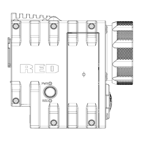
- Page 212 EPIC/SCARLET OPERATION GUIDE SIDE VIEW (LEFT) Figure: EPIC Side View (Left) C O PYR I G HT © 2 0 1 6 R ED.C O M , I NC 9 5 5 - 0 0 2 0 _V 6 .3 , R EV - F | 2 1 2...
- Page 213 EPIC/SCARLET OPERATION GUIDE TOP VIEW Figure: EPIC Top View C O PYR I G HT © 2 0 1 6 R ED.C O M , I NC 9 5 5 - 0 0 2 0 _V 6 .3 , R EV - F | 2 1 3...
- Page 214 EPIC/SCARLET OPERATION GUIDE BOTTOM VIEW Figure: EPIC Bottom View C O PYR I G HT © 2 0 1 6 R ED.C O M , I NC 9 5 5 - 0 0 2 0 _V 6 .3 , R EV - F | 2 1 4...
- Page 215 EPIC/SCARLET OPERATION GUIDE BACK VIEW Figure: EPIC Back View C O PYR I G HT © 2 0 1 6 R ED.C O M , I NC 9 5 5 - 0 0 2 0 _V 6 .3 , R EV - F | 2 1 5...
-
Page 216: Scarlet Brain
EPIC/SCARLET OPERATION GUIDE SCARLET BRAIN NOTE: Dimensions are shown in mm. The optical axis height of all EPIC/SCARLET cameras is 95.90 mm. FRONT VIEW Figure: SCARLET Front View C O PYR I G HT © 2 0 1 6 R ED.C O M , I NC 9 5 5 - 0 0 2 0 _V 6 .3 , R EV - F | ... - Page 217 EPIC/SCARLET OPERATION GUIDE SIDE VIEW (LEFT) Figure: SCARLET Side View (Left) C O PYR I G HT © 2 0 1 6 R ED.C O M , I NC 9 5 5 - 0 0 2 0 _V 6 .3 , R EV - F | 2 1 7...
- Page 218 EPIC/SCARLET OPERATION GUIDE TOP VIEW Figure: SCARLET Top View C O PYR I G HT © 2 0 1 6 R ED.C O M , I NC 9 5 5 - 0 0 2 0 _V 6 .3 , R EV - F | 2 1 8...
- Page 219 EPIC/SCARLET OPERATION GUIDE BOTTOM VIEW Figure: SCARLET Bottom View C O PYR I G HT © 2 0 1 6 R ED.C O M , I NC 9 5 5 - 0 0 2 0 _V 6 .3 , R EV - F | 2 1 9...
- Page 220 EPIC/SCARLET OPERATION GUIDE BACK VIEW Figure: SCARLET Back View C O PYR I G HT © 2 0 1 6 R ED.C O M , I NC 9 5 5 - 0 0 2 0 _V 6 .3 , R EV - F | 2 2 0...
-
Page 221: C Input/Output Connectors
This appendix provides pinout information for the input/output connectors on the camera. NOTE: When connecting a cable to a connector, align the key and red marker on the cable connector with the corresponding key and marker on the device connection. -
Page 222: Dsmc Brain
EPIC/SCARLET OPERATION GUIDE DSMC BRAIN Figure: BRAIN Connectors CONNECTOR CONNECTOR TYPE FOR MORE INFORMATION, GO TO... HD-SDI "3G-SDI (HD-SDI) Out" on the next page Headphone Jack 3.5mm stereo "Headphone" on page 229 ® SYNC 4-pin 00B LEMO "Communication Ports" on page 225 CTRL 4-pin 00B LEMO "CTRL (RS232 Control)"... -
Page 223: Record/Monitor Out Ports
Camera ground COMPATIBLE CABLE 790-0341: RED® HD-SDI Cable (6') C O PYR I G HT © 2 0 1 6 R ED.C O M , I NC 9 5 5 - 0 0 2 0 _V 6 .3 , R EV - F | 2 2 3... -
Page 224: Hdmi Out
2. The HDMI output is progressive scan (p); it does not support progressive segmented frame (PsF) or interlaced (i) scan formats. COMPATIBLE CABLE 790-0331: RED HDMI Cable (5') C O PYR I G HT © 2 0 1 6 R ED.C O M , I NC... -
Page 225: Communication Ports
EPIC/SCARLET OPERATION GUIDE COMMUNICATION PORTS SYNC (VIDEO SYNC IN) The 4-pin 00B LEMO SYNC connector accepts timecode, genlock, and General Purpose Input (GPI) signals. Figure: Front Face of the SYNC (Video Sync) Connector (Looking at the Camera) 4-PIN 00B LEMO SYNC CONNECTOR SIGNAL DESCRIPTION DIRECTION... - Page 226 790-0154: 3BNC-to-00 LEMO Sync Cable 790-0187: 4-Pin 00 LEMO-to-Flying Lead 790-0415: RED Start/Stop Cable (14-Pin LEMO to SYNC, CTRL, BNC) 790-0428: RED Start/Stop Cable (14-Pin to 00B SYNC) C O PYR I G HT © 2 0 1 6 R ED.C O M , I NC...
- Page 227 790-0154: 3BNC-to-00 LEMO Sync Cable 790-0187: 4-Pin 00 LEMO-to-Flying Lead 790-0415: RED Start/Stop Cable (14-Pin LEMO to SYNC, CTRL, BNC) C O PYR I G HT © 2 0 1 6 R ED.C O M , I NC 9 5 5 - 0 0 2 0 _V 6 .3 , R EV - F | 2 2 7...
- Page 228 Do not connect NOTE: Mating connector is FGG.0B.309.CLAD. COMPATIBLE CABLES 790-0159: RED GIG-E Straight-to-CAT5E Ethernet Cable (9') 790-0557: RED GIG-E Right-to-CAT5E Ethernet Cable (9') 790-0163: Master/Slave Gig-E Cable (4') C O PYR I G HT © 2 0 1 6 R ED.C O M , I NC...
-
Page 229: Audio Ports
EPIC/SCARLET OPERATION GUIDE AUDIO PORTS MIC-1, MIC-2 (MICROPHONE AUDIO) The two (2) 3.5mm microphone jacks are microphone level analog audio inputs. Each jack has 2.4K ohm of nominal impedance. For more information, go to "Record and Monitor Audio" on page 151. MIC-1: Ch1 MIC-2: Ch2 MICROPHONE JACK... -
Page 230: Power Ports
SDA-BATT Serial battery bus data NOTE: Mating connector is FGJ.1B.306.CWLD72Z. COMPATIBLE CABLES 790-0138: RED 2B-to-1B LEMO Power Adaptor Cable 790-0164: XLR Power Cable (10') 790-0165: XLR Power Cable (30") SSD MODULE CONNECTORS The connectors for the side SSD modules and the Rear SSD Module are described in the DSMC Media Operation Guide, available at www.red.com/downloads. -
Page 231: D Lens Mounts And Lenses
NOTE: HDRX is not availabe when the MOTION MOUNT Shutter Type is set to Soft or Square. REMOVE A LENS MOUNT NOTE: You can change lens mounts in the field. However, RED® recommends that you change lens mounts only in a dust-free environment. - Page 232 EPIC/SCARLET OPERATION GUIDE 5. Loosen and remove the four (4) M4x0.7 x 8 mm lens mount screws in a cross pattern (“X” pattern) using a T20 TORX driver. NOTE: The DSMC Mg PL Mount 2.0 has captive screws that are not removable from the mount. NOTE: Screw removal may require a large handle T20 TORX driver and additional leverage.
- Page 233 EPIC/SCARLET OPERATION GUIDE INSTALL A LENS MOUNT NOTE: You can change lens mounts in the field. However, RED recommends that you change lens mounts only in a dust-free environment. REQUIRED TOOLS: T20 TORX driver 1. Ensure that the camera is turned off and remove any accessories or cables that may interfere with installation.
- Page 234 EPIC/SCARLET OPERATION GUIDE 5. Replace and loosely tighten the four (4) M4x0.7 x 8 mm lens mount screws in a cross pattern (“X” pattern) using a T20 TORX driver. WARNING: DO NOT FULLY TIGHTEN. NOTE: The DSMC Mg PL Mount 2.0 has captive screws that are not removable from the mount. Figure: Tighten Screws 6.
-
Page 235: Lenses
CAMERA PL MOUNT SUPPORTED LENSES The DSMC Mg PL Mount 2.0, DSMC TI PL Mount, and the RED MOTION MOUNT Ti PL are compatible with most standard PL mount cinema lenses and devices. For information about the compatibility of the RED MOTION MOUNT... - Page 236 In the camera, go to Menu > Settings > Setup > Lens, and select the Enable Power to Lens check box. RED recommends using an external battery for the lens, since the lens mount provides a limited supply of power to the lens.
- Page 237 3. Remove the rear lens cap. 4. Align the red dot on the lens with the red dot on the DSMC Canon Mount and position the lens in the mount. 5. Turn the lens clockwise until it clicks into place.
- Page 238 EPIC/SCARLET OPERATION GUIDE DSMC CANON MOUNT SUPPORTED LENSES The DSMC Canon Mount and DSMC Canon MOTION MOUNT electronically support the following lenses: COMPATIBLE LENS TYPE FOCAL LENGTH Canon EF Canon EF 8-15mm f/4L Fisheye USM Canon EF 11-24mm f/4L USM Canon EF 14mm f/2.8L II USM Canon EF 15mm f/2.8 Fisheye Canon EF 15-85mm f/3.5 IS USM...
- Page 239 EPIC/SCARLET OPERATION GUIDE COMPATIBLE LENS TYPE FOCAL LENGTH Canon EF Canon EF 70-200mm f/2.8L USM Canon EF 70-200mm f/4L Canon EF 70-200mm f/4L with 1.4x Extender Canon EF 70-200mm f/4L with 2x Extender Canon EF 70-300mm f/4.5-5.6 DO IS USM Canon EF 70-300mm f/4-5.6L IS Canon EF 70-300mm f/4-5.6L IS USM Canon EF 85mm f/1.2L II...
- Page 240 EPIC/SCARLET OPERATION GUIDE COMPATIBLE LENS TYPE FOCAL LENGTH Canon EF 300mm f/4L IS Canon EF 300mm f/4.0 L IS with 1.4x Extender Canon EF 300mm f/4.0 L IS with 2.0x Extender Canon EF 400mm f/2.8 Canon EF 400mm f/2.8 IS II USM Canon EF 400mm f/2.8L IS Canon EF 400mm f/2.8L IS with 1.4x Extender Canon EF 400mm f/2.8L IS with 2x Extender...
- Page 241 EPIC/SCARLET OPERATION GUIDE COMPATIBLE LENS TYPE FOCAL LENGTH Sigma Sigma 10-20mm f/3.5 EX DC HSM Sigma 15mm f/2.8 EX DG Diagonal Fisheye Sigma 17-70mm f/2.8-4 DC Macro OS HSM Sigma 18-35mm f/1.8 DC HSM Art Sigma 20mm f/1.8 EX DG ASP RF Sigma 24mm f/1.8 EX DG ASP Macro AF Sigma 24-35mm f/2 DG HSM Art Sigma 24-70mm f/2.8 IF EX DG HSM...
- Page 242 EPIC/SCARLET OPERATION GUIDE COMPATIBLE LENS TYPE FOCAL LENGTH ® Zeiss Distagon Zeiss Distagon T* 15mm f/2.8 ZE Zeiss Distagon T* 18mm f/3.5 ZE Zeiss Distagon T* 21mm f2.8 ZE Zeiss Distagon T* 25mm f/2 ZE Zeiss Distagon T* 28mm f/2 ZE Zeiss Distagon T* 35mm f2 ZE ®...
- Page 243 EPIC/SCARLET OPERATION GUIDE NIKON F-MOUNT LENSES This section describes the appropriate method for attaching and detaching Nikon® F- Mount lenses. For more information, refer to the original manufacturer’s instructions. This section also lists lenses supported by the DSMC Nikon F-Mount. WARNING: ALWAYS protect your equipment, when it is not in use, by replacing lens caps and mount caps.
- Page 244 EPIC/SCARLET OPERATION GUIDE COMPATIBLE LENS TYPE FOCAL LENGTH Nikkor AF-S AF-S Nikkor 10-24mm f/3.5-4.5G ED DX AF-S Nikkor 12-24mm f4G ED DX AF-S Nikkor 14-24mm f/2.8G ED AF-S Nikkor 17-35mm f/2.8D ED IF AF-S Nikkor 17-55mm f/2.8G ED DX AF-S Nikkor 20mm f/1.8G ED N AF-S Nikkor 24mm f/1.4G ED AF-S Nikkor 24-70mm f/2.8G ED AF-S Nikkor 35mm f/1.4G...
- Page 245 EPIC/SCARLET OPERATION GUIDE COMPATIBLE LENS TYPE FOCAL LENGTH 1, 2 1, 2 Zeiss Otus Zeiss Otus 55mm f/1.4 Zeiss Otus 85mm f/1.4 ZF.2 APO Zeiss Planar Zeiss Planar T* 50mm f/1.4 ZF.2 Zeiss Planar T* 85mm f/1.4 ZF.2 1. Iris control only, no AF. 2.
- Page 246 EPIC MYSTERIUM-X and SCARLET MYSTERIUM-X. For more information, go to OLPF Frame Installation Instructions available at www.red.com/downloads. WARNING: Attempting to mount Leica lenses of focal lengths of less than 50mm could result in damage to the lens and/or the camera.
-
Page 247: E Default Key Functions
EPIC/SCARLET OPERATION GUIDE DEFAULT KEY FUNCTIONS DEFAULT KEYS DEFAULT KEY FUNCTIONS ITEM FUNCTION ® Camera BRAIN Record Full Press Record: Toggle GPI In High Record: Start GPI In Low Record: Stop Side SSD Module Record Full Press Record: Toggle/Multi-Shot Start Record Full Release Record: Multi-Shot Stop Record Half Press... - Page 248 EPIC/SCARLET OPERATION GUIDE DEFAULT KEY FUNCTIONS ITEM FUNCTION DSMC Side Handle User 1 Press SH: Key 1 User 2 Press SH: Key 2 User 3 Press SH: Key 3 User 4 Press SH: Key 4 User 5 Press Exposure Check: Toggle User 6 Press Key Disabled User 7 Press...
- Page 249 EPIC/SCARLET OPERATION GUIDE DEFAULT KEY FUNCTIONS ITEM FUNCTION RED Switchblade-M User A Press AF Mode: Cycle User B Press WB: Auto Calc User C Press Magnify: Toggle User D Press Exposure Check: Toggle User A+D Press SM: Toggle Key Lock...
- Page 250 EPIC/SCARLET OPERATION GUIDE DEFAULT KEY FUNCTIONS ITEM FUNCTION ® REDMOTE User A Press AF Mode: Cycle User B Press WB: Auto Calc User C Press Magnify: Toggle User D Press Exposure Check: Toggle Still Select Focus Mode: Still Movie Select Focus Mode: Motion Nav Menu Press Navigation: Menu...
-
Page 251: Preset Default Key Functions
EPIC/SCARLET OPERATION GUIDE PRESET DEFAULT KEY FUNCTIONS The following table describes default key functions for the Default Stills and Motion presets. NOTE: You cannot update factory-installed presets, which end with “(RED)”. PRESET DEFAULT KEY FUNCTIONS ITEM FUNCTION Default Stills Preset (RED) -
Page 252: F Menu Map
EPIC/SCARLET OPERATION GUIDE MENU The menu map is applicable to the following cameras, except as noted throughout this guide: EPIC-M RED DRAGON® (Carbon Fiber) EPIC-M RED DRAGON EPIC-X RED DRAGON SCARLET DRAGON® EPIC-M MYSTERIUM-X® EPIC-X MYSTERIUM-X SCARLET-X MYSTERIUM-X EPIC-M Monochrome... - Page 253 } Focus 1. Only available when a REDCAST™ Module is attached. } Iris 2. Not available on any BRAIN with a Monochrome or RED DRAGON Monochrome sensor. } Zoom 3. Only available when a MOTION MOUNT is attached. } Wireless 4.
Need help?
Do you have a question about the EPIC-M RED DRAGON (Carbon Fiber) and is the answer not in the manual?
Questions and answers