Table of Contents
Advertisement
Quick Links
Advertisement
Table of Contents

Related Manuals for RED EPIC-M


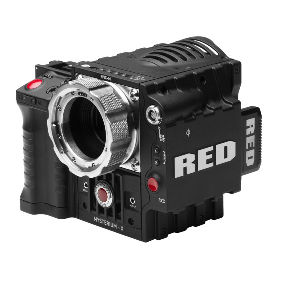
Summary of Contents for RED EPIC-M
-
Page 2: Table Of Contents
® FIRST TIME USE – SETTING Lens ........87 REDMOTE ® .......15 UP YOUR RED EPIC ....57 Exposure Menu ......88 Digital Magazine (Media) ...15 Attach Power Source ....57 Presets Menu ......88 Metadata ......16 Camera Presets ....88 Battery ......... - Page 3 APPENDIX M: MENU MAPS ..234 Side SSD Module ....171 Underexposure (~ 2 stops) ..210 REDMOTE ......172 Overexposure (~ 2 stops) ..212 RED EPIC Operation Guide ® EPIC-M / EPIC-X Version 3.2, Rev-A1 COPYRIGHT © 2012 RED Digital Cinema 955-0002_v3.2, Rev-A1...
-
Page 4: Disclaimer
RED reserves the right to revise this Operation Guide and make changes from time to time in the content hereof without obligation to notify any person of such revisions or changes. In no event shall RED, its employees or authorized agents be liable to you for any damages or losses, direct or indirect, arising from the use of any technical or operational information contained in this document. -
Page 5: Compliance
(2) this device must accept any interference received, including interference that may cause undesirable interference. CAUTION: If the device is changed or modified without permission from RED, the user may void his or her authority to operate the equipment. COPYRIGHT © 2012 RED Digital Cinema... -
Page 6: Australia And New Zealand Statement
Install and use the equipment according to the instruction manual. EUROPEAN UNION COMPLIANCE STATEMENTS RED declares that the equipment described in this document is in conformance with the requirements of the European Council EMC Directive 2004/108/EC, Low Voltage Directive 2006/95/EC, RoHS Directive 2002/95/EC and WEEE Directive 2002/96/EC. - Page 7 For business users in the European Union, if you wish to discard electrical and electronic equipment, please contact your dealer or supplier for further information. Responsible party: Red Digital Cinema ® 34 Parker Irvine, CA 92618 COPYRIGHT © 2012 RED Digital Cinema 955-0002_v3.2, Rev-A1...
-
Page 8: Before You Start
There are no user-serviceable parts inside. Alteration or repairs made to the camera, lens or other accessory, except by a RED authorized service facility, will void the Limited Warranty. Users are not permitted to make design changes or otherwise modify the operation of the camera, lenses or other accessories, without the express written approval of RED DIGITAL CINEMA. - Page 9 If there are any performance issues with your camera or accessories when operating within this temperature range, please file a support ticket on www.RED.com/support. O. The Side Handle, Side SSD Module, Rear Modules and Lens Mount are NOT HOT SWAPPABLE –...
- Page 10 WARNING: Do not expose the battery to excessive heat. WARNING: Danger of explosion if an incorrect battery is charged with the RED Charger or is used to power the camera and accessories. Replace only with the same or equivalent type battery.
-
Page 11: Theory Of Operation
A B4 mount to PL mount adaptor is also available to permit use of 2/3” HD broadcast lenses on the RED DSMC camera. The optical coverage it provides is approximately equivalent to 16mm, hence the maximum recording resolution operating with a B4 mount 2/3”... -
Page 12: Hdrx
• Use the X-track data for motion tracking, then combine the X-track with the A-track, or just motion stabilize the A-track using the motion analysis data extracted from the X-track. 955-0002_v3.2, Rev-A1 COPYRIGHT © 2012 RED Digital Cinema... -
Page 13: Magic Motion
AUDIO RECORDING The RED DSMC camera can record up to two discreet channels of microphone level uncompressed 24- bit, 48 KHz audio (four channels of microphone level or line level audio inputs when equipped with a PRO I/O Module), that are synchronized with video and timecode to a REDMAG 1.8”... -
Page 14: Line Level Analog Inputs
20dB above 0VU reference level) and maximizes the signal to noise ratio of the 24-bit digital recording. VIDEO MONITORING OUTPUTS In its default configuration, the RED DSMC camera can simultaneously support one VIEWFINDER output (suitable for use by a BOMB EVF , or RED LCD) plus one PROGRAM output and one PREVIEW output ®... - Page 15 For applications where use of an attached RED EVF or RED LCD is not desired – for example when working on a crane – the VIEWFINDER / MENU output can be transferred to the HD-SDI or HDMI outputs, supporting remote camera monitoring up to 200 ft away.
-
Page 16: Redmote
REDMOTE ® REDMOTE is a camera control unit for RED’s family of DSMC cameras that attaches to the rear of the camera Brain or rearmost expansion module. REDMOTE may also be detached from the camera or rearmost module and provide wireless remote control of the camera over proprietary REDlink™ protocol. -
Page 17: Metadata
Typical Magazine Folder and clip structure For additional information about digital magazines, refer to APPENDIX B: MANAGING DIGITAL MEDIA. METADATA RED’s family of DSMC cameras record the Metadata, which is data for each frame of the recording: • • •... - Page 18 So a three Clip sequence of Clip Folders within a Magazine Folder on Camera A would look like this: A001_C001_0502**.RDC A001_C002_0502**.RDC A001_C003_0502**.RDC 955-0002_v3.2, Rev-A1 COPYRIGHT © 2012 RED Digital Cinema...
-
Page 19: Smpte Timecode
Under typical operating conditions, a REDVOLT ® battery will run the camera and accessories for about 30 minutes and a REDVOLT XL battery will run the camera and accessories for about 90 minutes. ® COPYRIGHT © 2012 RED Digital Cinema 955-0002_v3.2, Rev-A1... -
Page 20: Camera Operational Controls
CAMERA OPERATIONAL CONTROLS This section describes the available operational controls on the RED DSMC camera Brain, Side SSD Module, Side Handle and REDMOTE accessories. BRAIN Power Status LED Power / Record Button Record Status LED Power / Record Button / Status LEDs •... -
Page 21: Side Ssd Module
LED Red Blinking = Power present. Less than 5 minutes of Battery time left • Record Status LED: Indicates record status: o LED Off = No Media present. o LED Green = Ready to Record o LED Red Constant = Recording... - Page 22 LED Off = No Media o LED Green = Ready to Record o LED Red Constant = Recording o LED Red Slow Blink = Recording, 25% Media Left o LED Red Fast Blink = Recording, 5% Media Left o LED Yellow = Finalizing o LED Yellow Blinking = Media Access (Format etc...)
-
Page 23: Side Handle
Focus / Record Button LCD Display Adjustment Ring LCD Backlight Button RED Side Handle Controls - Top • Battery Door Release Button: Releases Side Handle battery door to permit battery exchange. • Focus / Record Button: Touch for Auto Focus, fully depress to Start or Stop Record. -
Page 24: Front
Side Handle Controls - Front • Stills / Movie Slider: Selects between STILLS and MOVIE modes of operation. NOTE: This switch is not active at this time. Default camera operation is MOVIE 955-0002_v3.2, Rev-A1 COPYRIGHT © 2012 RED Digital Cinema... -
Page 25: Rear
REAR RED Side Handle Controls - Rear MENU Button User Keys A-D Rocker Switch System Keys 1- 3 Navigation Group Thumbwheel Lock • Menu Button: Press to access / camera setup menus. • Rocker Switch: Increases or decreases selected value based on parameter selected in USER KEYs. - Page 26 User Key D – Toggles False Color > Exposure Check • System Keys: Function is defined by System Firmware. Upper: Toggles False Color > Exposure Check Center: Not currently defined Lower: Ejects (unmounts) the currently selected Media 955-0002_v3.2, Rev-A1 COPYRIGHT © 2012 RED Digital Cinema...
-
Page 27: Installation / Removal
5. Rotate side handle down flush along side of camera brain. 6. Rotate thumbscrew upwards until tight. Ensure side handle is secure to camera brain. You may have to apply steady pressure to get the screw started. COPYRIGHT © 2012 RED Digital Cinema 955-0002_v3.2, Rev-A1... - Page 28 Rotate side handle upwards to remove. Rotate thumbscrew downwards until loose. 3. Rotate upwards and pull down to disengage lip at top of side handle from camera brain. 4. Remove side handle from camera. 955-0002_v3.2, Rev-A1 COPYRIGHT © 2012 RED Digital Cinema...
-
Page 29: Dsmc Modules
QUAD BATTERY MODULE • The QUAD MATTERY MODULE holds up to 4 REDVOLTs or 2 REDVOLT-XLs • Batteries may be hot swapped Battery Eject Button Quad Battery Module – Shown with REDVOLT batteries Installed COPYRIGHT © 2012 RED Digital Cinema 955-0002_v3.2, Rev-A1... -
Page 30: Dual Battery Module
DUAL BATTERY MODULE • The DUAL BATTERY MODULE holds up to 2 REDVOLTs • Batteries may be hot swapped Dual Battery Module – Shown with REDVOLT batteries Installed 955-0002_v3.2, Rev-A1 COPYRIGHT © 2012 RED Digital Cinema... -
Page 31: Module Installation / Removal
2. Remove the REDMOTE. 3. Place the adapter plate over the v-mount on the rear of the camera brain. 4. Using a T-20 Torx, lightly tighten the four screws. Do not over tighten. COPYRIGHT © 2012 RED Digital Cinema 955-0002_v3.2, Rev-A1... - Page 32 5. Tighten the screws again in a cross pattern until tight. 955-0002_v3.2, Rev-A1 COPYRIGHT © 2012 RED Digital Cinema...
- Page 33 1. Insert the lip at the top of the module into the recess at the top of the adaptor plate. Insert Lip At Top of Adaptor Plate Rotate Module Down Until Flush with Adaptor COPYRIGHT © 2012 RED Digital Cinema 955-0002_v3.2, Rev-A1...
- Page 34 2. Use a T-20 Torx screwdriver to rotate the lock on the adapter plate to the Unlock position. 3. Rotate the module upwards and down to disengage lip at top of battery from adaptor plate. 4. Remove module from adapter plate. 955-0002_v3.2, Rev-A1 COPYRIGHT © 2012 RED Digital Cinema...
-
Page 35: Redmote
Stills / Motion Slider: Allows selection of STILLS or MOVIE operational modes. • Rocker Switch: Provides continuous adjustment of parameter specified in USER KEYS menu. • User Keys: Press to initiate camera functions as defined in USER KEY menu. COPYRIGHT © 2012 RED Digital Cinema 955-0002_v3.2, Rev-A1... - Page 36 OPERATION > REDMOTE MENUS > SOFT MENU BUTTONS 4-8. • Power / Lock Slider: Slide and hold down for two seconds to power up / down REDMOTE and or camera. Slide up to lock keys. 955-0002_v3.2, Rev-A1 COPYRIGHT © 2012 RED Digital Cinema...
-
Page 37: Displays
Available diopter range: +2.0 to -5.0.l Talley Light Focus Ring Brightness Controls RED BOMB EVF (OLED) brings advanced OLED technology into the field, providing truer blacks and more color accurate images • Resolution: 1280 (wide) x 1024 (high) full-color •... -
Page 38: Touchscreen Lcd
TOUCHSCREEN LCD Red offers a five inch touch screen LCD with 800 X 400 resolution and 4:4:4 progressive scan. The touchscreen LCD allows navigation of camera menus and selection and adjustment of camera parameters by directly touching icons on the screen. Gestures supported include: •... -
Page 39: Basic Operation
Power draw is prioritized as follows when multiple power sources are available to the camera. 1. DC (Voltage) or Brick (%) 2. Battery Module batteries 3. Side Handle battery POWER SOURCES SIDE HANDLE The optional Side Handle accepts one REDVOLT. Side Handle Battery Compartment COPYRIGHT © 2012 RED Digital Cinema 955-0002_v3.2, Rev-A1... -
Page 40: Quad Battery Module
Quad Battery Module for re-charging, and a new charged battery may be inserted in its place. i.e. batteries may be hot swapped, there is no need for the operator to power down the camera to replace a REDVOLT battery when using the Quad Battery Module. 955-0002_v3.2, Rev-A1 COPYRIGHT © 2012 RED Digital Cinema... -
Page 41: Backpack Quickplate
The optional BACKPACK QUICKPLATE attaches directly to the back of the DSMC BACKPACK to provide a compact REDBRICK configuration for EPIC or SCARLET-X. Note: DSMC BACKPACK is required for use of the BACKPACK QUICKPLATE BACKPACK QUICKPLATE REDBRICK COPYRIGHT © 2012 RED Digital Cinema 955-0002_v3.2, Rev-A1... -
Page 42: Ac Power Adaptor - (Dsmc)
• LED Yellow Blinking = Battery has 10 minutes of run time remaining • LED Red Blinking = Battery has 5 minutes of run time remaining • LED Constant Red = Battery Discharged Remaining batteries will have a steady LED on module. -
Page 43: External Dc Power
Battery location and status are also displayed on REDMOTE. In this case RM B3 (Rear Module, Bay 3). The POWER menu also shows all installed batteries and their state of charge. EXTERNAL DC POWER RED DSMC Cameras accept input voltages between 11.5V - 17V D.C and can draw a maximum current of 12 Amps. •... -
Page 44: Power Up
Power / Record Button / Status LEDs When an appropriate power source is connected to the Brain, the Power Status LED will illuminate Red. If it is illuminated, depress and then release the Power / Record button. The Power Status LED will initially go out and within 5 seconds illuminate Orange to confirm the camera is powering up, then it will illuminate Green, confirming the camera is powered up and ready to use. -
Page 45: Power Down
2. Depress and continue to hold the Power / Record button in its fully depressed position until the INITIATING CAMERA SHUTDOWN shows on the display. After Power Down, the Power Status LED will illuminate Red, if an appropriate power source is available. COPYRIGHT © 2012 RED Digital Cinema... -
Page 46: Graphical User Interface And Navigation
GRAPHICAL USER INTERFACE AND NAVIGATION RED LCD/TOUCHSCREEN LCD, BOMB EVF, EXTERNAL MONITORS The following is a general description of the structure of the camera’s Graphical User Interface (GUI) which overlays the video monitor signal on the Viewfinder output(s) of the camera. - Page 47 LCD - Accesses the Playback Function • Magnify: Tallies 1:1 if magnify is selected • TC: Indicates presence of valid SMPTE timecode signal and Jam Sync status COPYRIGHT © 2012 RED Digital Cinema 955-0002_v3.2, Rev-A1...
- Page 48 NOTE: Shutter angle is displayed in Relative mode by default, as indicated by Yellow text. If the red bar is not on the parameter you wish to change, first use the Scroll Wheel to position the red bar under that parameter, then press ENTER, adjust with the Scroll Wheel and press ENTER a second time to confirm the value change.
- Page 49 TC Gray - No analog time code is currently detected. • TC Red - Analog time code is being detected, but the use of it is not enabled. • TC Green - Analog time code is being used to jam the time of day time code. TC will revert to gray if the signal is no longer detected.
- Page 50 Green: >10 minutes Yellow: 5-10 minutes Red: <5 minutes If using a RED BRICK battery connected to DC IN, power status displays BRICK and reports the % of remaining battery capacity and the displayed text is color coded as follows: •...
- Page 51 RAW CLIP METER The RAW Clip meter looks a traffic light style meter and indicates if either of the Red, Blue or Green channels of the RAW sensor data are clipping. This meter is unaffected by White Balance, ISO, VIEW or LOOK settings and therefore represents a true measurement of the exposure levels of the sensor at all times.
-
Page 52: Side Handle
• Wireless Status: Displays signal strength • Frame Rate: Image capture rate when connected wirelessly • • ISO Rating: Camera sensitivity Battery Indicator: Displays battery life or charge status (shown) of REDMOTE 955-0002_v3.2, Rev-A1 COPYRIGHT © 2012 RED Digital Cinema... -
Page 53: Navigating Menus
Selects Advanced Settings menu. DOWN Selects standard Settings menu. As an example, position the Cursor under the Shutter Speed (24FPS) icon and press the UP Direction Key to access advanced adjustment values for Shutter Speed. COPYRIGHT © 2012 RED Digital Cinema 955-0002_v3.2, Rev-A1... -
Page 54: Using Touchscreen Lcd
To enter the Secondary Menus, touch the MENU icon. • To return to the Main Menus, touch the MENU icon again. • To access the Playback function, touch the arrow. • To exit the Playback function, touch the circle. 955-0002_v3.2, Rev-A1 COPYRIGHT © 2012 RED Digital Cinema... -
Page 55: Touchscreen Shortcuts
TOUCHSCREEN SHORTCUTS The bottom portion of the touchscreen contains shortcuts to the most-used camera screens. COPYRIGHT © 2012 RED Digital Cinema 955-0002_v3.2, Rev-A1... -
Page 56: Power Down
USING POWER STATUS DISPLAY 1. Select the POWER status located between the audio channels and media remaining indicator, to reveal the same menu illustrated above. 2. Select SHUTDOWN. 3. The camera will immediately power down. 955-0002_v3.2, Rev-A1 COPYRIGHT © 2012 RED Digital Cinema... -
Page 57: Lock / Unlock Touchscreen Opreration
When locked, the main menu will be displayed. UNLOCK To unlock out the touchscreen and allow normal operation, touch and hold the LOCK icon until the MENU icon displays; indicating the touchscreen has been unlocked. COPYRIGHT © 2012 RED Digital Cinema 955-0002_v3.2, Rev-A1... -
Page 58: First Time Use - Setting Up Your Red Epic
DC IN power supply has priority and will power the camera instead of the battery. BATTERY Connect a RED battery to the camera in one of the following ways: SIDE HANDLE Attach a Side Handle and insert a REDVOLT battery. -
Page 59: Quad Battery Module
Insert battery into desired location and press until a click is heard and battery is seated. REMOVE 1. Press the battery eject button (A) for desired battery. 2. When battery pops out, remove battery from battery module (B). COPYRIGHT © 2012 RED Digital Cinema 955-0002_v3.2, Rev-A1... -
Page 60: Red Brick
Identify a REDMAG 1.8” 64GB, 128GB or 256GB SSD that has not previously been recorded to, or is not a camera master and may therefore be erased and re-used. Aligned the RED logo of the SSD to the outside, and then push the SSD firmly, but without excessive force, into the slot in the Side SSD Module. - Page 61 When FORMAT is selected, a FORMAT dialog box will appear allowing you to add Camera Identity and 3D Position properties when formatting. When desired options are set, select FORMAT. NOTE: If any clips will be erased on the attached media, you will be informed of the number. COPYRIGHT © 2012 RED Digital Cinema 955-0002_v3.2, Rev-A1...
-
Page 62: Perform A Black Shading Calibration
It is also the primary frame rate for acquisition, but variable speed (over-crank and under-crank) recordings can be made above and below this base frame rate using the VARISPEED menu. 955-0002_v3.2, Rev-A1 COPYRIGHT © 2012 RED Digital Cinema... - Page 63 The current compression ratio will automatically be re-calculated when changes are made to Resolution, FPS, HDRX Mode, Media, or Target REDCODE. COPYRIGHT © 2012 RED Digital Cinema 955-0002_v3.2, Rev-A1...
-
Page 64: Recording
Timecode, normally displayed in white colored text, will be displayed in red colored text. A small Red dot will appear in the top right corner of the VIEWFINDER output(s). The REC LED on the right side of the camera Brain will illuminate Red. -
Page 65: Playback
If using a BOMB-EVF, the LED on the front will illuminate Red if Tally is enabled SMPTE-RP188 timecode VITC-2 HANC metadata record flag will be enabled on HD-SDI outputs. If enabled in the USER KEYS menu, the GPO trigger output in the CNTL connector will pulse. -
Page 66: Menu Controls
Touch the desired parameter for adjustment. • Slide your finger across the screen to scroll through the available parameter values. • When desired the parameter value has been selected, touch anywhere in the screen area to set. 955-0002_v3.2, Rev-A1 COPYRIGHT © 2012 RED Digital Cinema... -
Page 67: Advanced Setting Menus
2. Press the field - a keypad type menu may appear to allow adjustments. 3. Press the desired parameter settings to adjust. 4. When desired selection is made, press anywhere in the screen area to set and exit the advanced settings submenu. COPYRIGHT © 2012 RED Digital Cinema 955-0002_v3.2, Rev-A1... -
Page 68: Main Menu
When a frame rate other than the current TIME BASE has been selected, the FPS text will turn Yellow and VARISPEED will be shown where the Audio Meter is normally displayed at the lower right of the display. 955-0002_v3.2, Rev-A1 COPYRIGHT © 2012 RED Digital Cinema... -
Page 69: Basic Settings
On Touchscreen systems, a Keypad is available for direct numeric entry of the VARISPEED FPS value. Touch the value bounded by the + and – labels to bring up, press outside the keypad to confirm the value. COPYRIGHT © 2012 RED Digital Cinema 955-0002_v3.2, Rev-A1... -
Page 70: Iso (Sensitivity)
You can chose either 1/3 or 1/4 stops. RED DSMC Ti PL Mount Installed When a lens equipped with Cooke’s S4/i system is attached to the DSMC Ti PL Mount, the camera will display the current aperture (F stop) of the attached lens. - Page 71 When selected, the advanced settings menu allows fine control over the f-stop value under APERTURE and focal distance under FOCUS. APERTURE (F STOP) Provides the ability to enter the F stop value directly. Range depends on attached lens. Default depends on attached lens. COPYRIGHT © 2012 RED Digital Cinema 955-0002_v3.2, Rev-A1...
-
Page 72: Exposure
Range is 1/24 sec – 1/8000 sec - Slowest available speed is 1 second per frame / frame rate, so for 24 fps it is 1/24 sec. Default is 1/48 Sec. 955-0002_v3.2, Rev-A1 COPYRIGHT © 2012 RED Digital Cinema... -
Page 73: Advanced Settings
Provides the ability to enter the Exposure value as a Shutter Speed (1/xx sec). Range is 2 – 1/8000 Sec - Slowest available speed is 1/frame rate, so for 24 fps it is 1/24 Sec. Default is 1/48 Sec. COPYRIGHT © 2012 RED Digital Cinema 955-0002_v3.2, Rev-A1... - Page 74 As you adjust any of these three parameters, the camera will automatically calculate the equivalent value in the other units, but as a quick reference here are some common Speeds and Angles. 955-0002_v3.2, Rev-A1 COPYRIGHT © 2012 RED Digital Cinema...
-
Page 75: White Balance
1/696 1/96 1/1000 WHITE BALANCE BASIC SETTINGS Allows you to manually set Color Temperature in the range from 1,700 to 100,000 KELVIN. Range is 1,700 K to 10,000 K. Default is 5600K. COPYRIGHT © 2012 RED Digital Cinema 955-0002_v3.2, Rev-A1... -
Page 76: Advanced Settings
CLOUDY FLASH TUNGSTEN Preset to 7,500K Preset to 5,500K Preset to 3,200K COLOR TEMP Allows you to manually set Color Temperature in the range from 1,700 to 100,000 KELVIN. Default is 5600K. 955-0002_v3.2, Rev-A1 COPYRIGHT © 2012 RED Digital Cinema... - Page 77 Calc White Balance function and then press the Calc White Balance function box. Calc White Balance is also assigned to a User Key on the REDMOTE and Side Handle as a factory default setting. COPYRIGHT © 2012 RED Digital Cinema 955-0002_v3.2, Rev-A1...
-
Page 78: Resolution
Use the scroll ribbon to select a target REDCODE compression ratio. The camera will automatically select the closest REDCODE to the desired target. The display will always show the "current" compression ratio being used by the camera. 955-0002_v3.2, Rev-A1 COPYRIGHT © 2012 RED Digital Cinema... -
Page 79: Redcode Options For Various Frame Rates
Available options in this menu screen are HDR, FOCUS, PRESETS, MEDIA, SETTINGS, and POWER. EXPOSURE is not implemented at this time. HDR MENU Available options are HDR OFF, HDRx and STOPS. NOTE: HDR mode cannot be modified when in Magnify 1:1 mode. COPYRIGHT © 2012 RED Digital Cinema 955-0002_v3.2, Rev-A1... -
Page 80: Hdr On / Off
To adjust the STOPS parameter, select the Stops box and use the UP / DOWN arrows to adjust. Range is 1 to 6. Default is 2. FOCUS MENU The Focus Menu is used to enable and select Focus parameters including MODE and ZONES. 955-0002_v3.2, Rev-A1 COPYRIGHT © 2012 RED Digital Cinema... -
Page 81: Mode
Enables the Center or Spot focus square for use with manual focus. This mode provides additional focus assistance to the photographer using RED, YELLOW, and GREEN color changes to the focus spot window. Inadequate subject illumination and/or contrast may interfere with normal Focus Confirm operation. - Page 82 Enables the Center or Spot focus square for use with manual focus. This mode provides additional focus assistance to the photographer using RED, YELLOW, and GREEN color changes to the focus spot window. Inadequate subject illumination and/or contrast may interfere with normal Focus Confirm operation.
- Page 83 Spot. On the other hand, when two rack points have already been defined, the rack point can be updated by moving the spot to a new location. This will replace the rack point that is not in focus at that moment. COPYRIGHT © 2012 RED Digital Cinema 955-0002_v3.2, Rev-A1...
-
Page 84: Dsmc Canon Mount Electronically Supported Lenses
Canon EF 600mm f/4L IS Zeiss Makro-Planar 50mm f/2 Canon EF 70-200mm f/2.8L IS Zeiss Planar T* 85mm f/1.4 Canon EF 70-200mm f/2.8L IS II USM Zeiss Makro-Planar 100mm f/2 Canon EF 70-200mm f/4L 955-0002_v3.2, Rev-A1 COPYRIGHT © 2012 RED Digital Cinema... -
Page 85: Zones
Provides a large, square target for focus. When objects located in the circle are in focus, the square will be Yellow or Green. When objects located in the square are out of focus, the square will be Red. COPYRIGHT © 2012 RED Digital Cinema... - Page 86 Provides a small, square target for precise focus (similar to Center focus, only smaller). When objects located in the square are in focus, the square will be Yellow or Green. When objects located in the square are out of focus, the square will be Red. SPOT FOCUS INDICATOR Moving The spot focus square can be moved around the screen.
- Page 87 1. Navigate to the focus menu. 2. Press the down arrow on the Navigation Group. 3. The spot focus square line weight will increase and the Red cursor under FOCUS will dim slightly. 4. Press the ENTER button. 5. Use the directional arrows to move the Spot Focus square to the desired location.
-
Page 88: Lens Information Display
RED DSMC TI PL MOUNT + LENS When a RED DSMC Ti PL Mount is installed and a Lens equipped with Cooke’s S4/i system (or equivalent is attached, the Focal Length and Focal Distance is displayed on the LCD, EVF and external monitors. -
Page 89: Exposure Menu
Custom presets may be created to store groups of camera settings. For example; White Balance and ISO settings for a particular shooting location can be captured and as a preset and easily recalled later. Presets can also be saved on an SSD and applied to other RED DSMC cameras. CREATING A PRESET •... - Page 90 Copy the desired settings from the left box of the interface to the right box using the (-->) select all button • Create Select and press button (upper right corner of the screen) The preset has been created and is now stored on the camera. 955-0002_v3.2, Rev-A1 COPYRIGHT © 2012 RED Digital Cinema...
- Page 91 SHARING PRESETS Presets may be shared between RED DSMC cameras using SSD media. Camera to camera Camera to multiple cameras Presets Select from the secondary menu: On SSD On Camera COPYRIGHT © 2012 RED Digital Cinema 955-0002_v3.2, Rev-A1...
- Page 92 The APPLY, DELETE, and CREATE buttons are only affect the camera box. Presets on the SSD will remain there until the media is reformatted. • S-SSD\Presets Camera Copy the desired settings from the side of the interface to the side using select one select all (-->) or button 955-0002_v3.2, Rev-A1 COPYRIGHT © 2012 RED Digital Cinema...
-
Page 93: Looks Presets
Meta is the default settings shot on the camera and cannot be deleted. As looks are created, they will be displayed alphabetically. For detailed information on LOOKs, see the REDCINE-X Operation Guide, available on RED.com COPYRIGHT © 2012 RED Digital Cinema... -
Page 94: Media Menu
When selected, a new dialog box will appear allowing you to add properties to the media highlighted in the Current Media box when formatting. Available options are REEL NO, CAM ID, CAM POS, and FORMAT to format the media with the values entered. 955-0002_v3.2, Rev-A1 COPYRIGHT © 2012 RED Digital Cinema... -
Page 95: Eject Media
REDMOTE will also display this message. EJECT MEDIA When selected will Eject (unmount) the media highlighted in the Select Media box. When ejected, camera will display “Media Ejected Successfully”. REDMOTE will also display this message. COPYRIGHT © 2012 RED Digital Cinema 955-0002_v3.2, Rev-A1... -
Page 96: Utilities
SSD is in question. NOTE: If clips are present on the media, you will be informed of how many clips will be erased when you secure format the media. 955-0002_v3.2, Rev-A1 COPYRIGHT © 2012 RED Digital Cinema... -
Page 97: Settings Menu
Available options are OFF, EXPOSURE, FOCUS, VIDEO, EDGE, MAGNIFY, and RAW. The Dialog is available by either going to SETTINGS > DISPLAY > TOOLS or simply clicking on the histogram in the lower left. Turns off any of the display modes in the first line. COPYRIGHT © 2012 RED Digital Cinema 955-0002_v3.2, Rev-A1... - Page 98 NOTE: Because the RAW data represents a wider color space than RGB, provided that the Red (clip) color is not present in EXPOSURE view, even if Red (clip) color is present in VIDEO view, the apparently clipped RGB highlights can be recovered in post-production by adjustment of ISO, FLUT or changing the KNEE and WHITE values of the CURVE box.
- Page 99 Green represents 18% Gray, Pink represents Skin Tone, Straw represents White, and Yellow, Orange and RED represent various degrees of signal clipping in RGB space. By adjusting ISO, FLUT and Shadow while looking at VIDEO check, the operator can ensure that Black, White and 18% Gray values conform to the desired levels on the HD-SDI and /or HDMI outputs.
- Page 100 When selected, the icon “F √” will be displayed in the Lower Status Group. WARNING: This will potentially interfere with recordings done via HDMI/HD-SDI in "Clean" Mode! 955-0002_v3.2, Rev-A1 COPYRIGHT © 2012 RED Digital Cinema...
- Page 101 NOTE: HDR mode cannot be modified when in Magnify 1:1 mode. NOTE: When in magnify mode, you will not be able to adjust frame rate or resolution. These options will be Grayed out. COPYRIGHT © 2012 RED Digital Cinema 955-0002_v3.2, Rev-A1...
- Page 102 Zebras enable and adjust the upper and lower values for two independent Zebra indicators. One zebra may be used for highlight exposure, and the other for mid tone or shadows. Zebras will be visible when in 1:1 zoom. By default, Zebra 1 and 2 are disabled. 955-0002_v3.2, Rev-A1 COPYRIGHT © 2012 RED Digital Cinema...
- Page 103 To enable, select ZEBRA 2 check box. Areas of the image exposed within these ranges will be indicated by crosshatched overlays at + 45 degrees relative to vertical. Zebra 2 is shown in the image below. High IRE Change the desired setting between 1 and 99 (default is 47). COPYRIGHT © 2012 RED Digital Cinema 955-0002_v3.2, Rev-A1...
- Page 104 Allows you to enable and color code graphic overlays visible the on the Viewfinder and Preview outputs. Use check boxes and pull down menus to control appearance of the overlays Grid The Grid display is shown below. The grid may be used as a “rule of thirds” indicator. 955-0002_v3.2, Rev-A1 COPYRIGHT © 2012 RED Digital Cinema...
- Page 105 Look Around Highlights the look around area. Overlay Elements Motion Data (Pitch & Roll) Lens Info 01:17:06:16 File Name Scene Name Time Code COPYRIGHT © 2012 RED Digital Cinema 955-0002_v3.2, Rev-A1...
- Page 106 NOTE: When operating in Relative mode, the shutter speed is reported in Yellow text. NOTE: If the operator requests a shutter speed that is outside the capability of the camera, the camera will automatically limit them when a limiting parameter changes. 955-0002_v3.2, Rev-A1 COPYRIGHT © 2012 RED Digital Cinema...
- Page 107 USER PREFERENCE, thereby permitting the camera guides to be fully customized for any application. Available options are Size, Line Style, Color and Transparency. COPYRIGHT © 2012 RED Digital Cinema 955-0002_v3.2, Rev-A1...
- Page 108 Available options are Solid, Dashed, or Bracket. COLOR Sets the frame guideline color to White, Gray, Teal, Purple, Yellow, Green, Blue, Red, or Black. Select the color that provides maximum color contrast with the scene you are shooting. Default is White.
-
Page 109: Look
REDCODE RAW data being recorded. COLOR The Color sub-menu permits adjustment of SATURATION, CONTRAST, and BRIGHTNESS. SATURATION Adjusts color saturation. Range is 0.0 (monochrome) to +3.8 (super color). Default is 1.0. COPYRIGHT © 2012 RED Digital Cinema 955-0002_v3.2, Rev-A1... - Page 110 GAIN The GAIN sub-menu permits adjustment of RED GAIN, BLUE GAIN and GREEN GAIN. Adjusts the gain of the RED channel only. Range is 0.0 (no Red) to 10.0. Default is 1.0. BLUE Adjusts the gain of the BLUE channel only. Range is 0.0 (no Blue) to 10.0. Default is 1.0.
- Page 111 Default is 0.0. Increasing the Shadow value raises the video level of near Blacks. Lowering the Shadow value crushes the video level of near Blacks. CURVES The curves dialog box allows the user to set define curves for Luminance, and the red, green, and blue channels. COPYRIGHT © 2012 RED Digital Cinema...
-
Page 112: Project
Available Color Space Options Available Gama Space Options PROJECT The project menu sets the operating parameters the camera will use for a given project. Options available are TIME BASE and TIME CODE. 955-0002_v3.2, Rev-A1 COPYRIGHT © 2012 RED Digital Cinema... - Page 113 Available options are 23.98, 24.00, 25.00, 29.97, 47.96, 48.00, 50.00, and 59.94. Default is 23.98. TIME CODE Selects the TIME CODE source to be used. Options are EXTERNAL TC and INTERNAL USER- PROVIDED TC. COPYRIGHT © 2012 RED Digital Cinema 955-0002_v3.2, Rev-A1...
- Page 114 When selected the camera uses the cameras Real Time Clock as the timecode counter source (snapshot of the RTC.) Set Manually When selected allows the user to define a custom value as the timecode counter seed. 955-0002_v3.2, Rev-A1 COPYRIGHT © 2012 RED Digital Cinema...
-
Page 115: System Status
Note: The scene name is limited to eight characters. Scene Information Camera Information Project Information Auto Slate Information SYSTEM STATUS Selecting System Status from the Project menu displays key project information. COPYRIGHT © 2012 RED Digital Cinema 955-0002_v3.2, Rev-A1... -
Page 116: Audio/Video
Menu adjusts AUDIO INPUT, AUDIO OUTPUT, AUDIO CHANNELS, MONITOR CONTROL, and TEST SIGNALS. AUDIO INPUT Allows you to enable / disable and adjust levels for audio inputs (CAM ANALOG). Default is unchecked. Range 8 to 64 dB, default is 10 dB. 955-0002_v3.2, Rev-A1 COPYRIGHT © 2012 RED Digital Cinema... - Page 117 Also, when audio is disabled and an audio jack is plugged in, the circle will remain Gray but the box around the signal will be highlighted (jack is detected by the camera). COPYRIGHT © 2012 RED Digital Cinema 955-0002_v3.2, Rev-A1...
- Page 118 Allows adjustment of audio output levels fed to the outputs. Available options for each channel are ON and MUTE. Default is ON at -9 dB. AUDIO CHANNELS Allows selection of audio inputs and operational modes. 955-0002_v3.2, Rev-A1 COPYRIGHT © 2012 RED Digital Cinema...
- Page 119 Available options are NONE, CAM ANALOG, PRO I/O ANALOG, PRO I/O AES A, and PRO I/O AES B. NOTE: For cameras not equipped with a PRO I/O module, options are NONE or CAM ANALOG. Mode Available options are UNBALANCED and BALANCED. Link Enables linkage between Channel Gain controls. COPYRIGHT © 2012 RED Digital Cinema 955-0002_v3.2, Rev-A1...
- Page 120 If anything other than MENUS is selected on the LCD (such as CLEAN), to return to displaying the MENUS, perform a double-tap on the LCD screen. HDMI Options are OFF, MENUS, PREVIEW, CLEAN, OVERLAY, 3D LEFT, and 3D RIGHT. 955-0002_v3.2, Rev-A1 COPYRIGHT © 2012 RED Digital Cinema...
- Page 121 Allows you to choose the output frequency in Hertz (Hz) for HD-SDI monitors. Available options are AUTO, 23.976/24, 25, 29.976, 47.952/48, 50, and 59.94. AUTOMATICALLY ASSIGN MENU SCREEN IF ENABLED When checked will assign an attached external monitor to display the menus if none are selected. COPYRIGHT © 2012 RED Digital Cinema 955-0002_v3.2, Rev-A1...
- Page 122 Enter or Menu button on the Side Handle or REDMOTE. SMPTE BARS CHIP CHART NOTE: RED DSMC test signals are not recordable, they are provided to help align external video monitors connected via the HD-SDI or HDMI outputs. 955-0002_v3.2, Rev-A1...
-
Page 123: Setup
Press the camera key you want to change. • Use the pull down to select the desired function • Press menu or a blank area of the touchscreen to save the setting COPYRIGHT © 2012 RED Digital Cinema 955-0002_v3.2, Rev-A1... - Page 124 The advanced tab allows you to set key functions using a series of pull down menus • Select Key Source (Brain, REDMOTE, Side SSD, etc.) • Select the key you wish to change • Select the desired key action Key Source 955-0002_v3.2, Rev-A1 COPYRIGHT © 2012 RED Digital Cinema...
- Page 125 User Key Key Action WARNING: Do not remap the navigation keys (Up, Down, Left, Right, Select (Enter), or Menu) on the side handle doing so could render the camera inoperabel. COPYRIGHT © 2012 RED Digital Cinema 955-0002_v3.2, Rev-A1...
- Page 126 This menu allows the user to reset the battery backed up internal clock of the camera. This time value is used as a timestamp on the .R3D files when recording to the RED MAG 1.8” SSD media. NOTE: Enter time in 24-hour clock format. i.e. 2:35 pm should be entered as 14:35:00.
- Page 127 The camera can communicate to external devices via RS232 Serial Port and / or the Gigabit Ethernet Port. This selection allows the user to specify the serial communications PROTOCOL. Available options are NONE, ELEMENT TECHNICA, 3ALITY SPC 7100 and 3ALITY SPC 7000. Default is NONE. COPYRIGHT © 2012 RED Digital Cinema 955-0002_v3.2, Rev-A1...
- Page 128 Permits the user to adjust the Subnet Mask the property on other cameras). SET commands address. sent to this camera will not be propagated. Gateway Permits the user to adjust the Gateway address. 955-0002_v3.2, Rev-A1 COPYRIGHT © 2012 RED Digital Cinema...
- Page 129 REDLink wireless connection in the event of interference from other wireless devices. Auto (unchecked) will pick the "cleanest" channel automatically on each camera boot. Manual Channel Select is the default setting and for default uses Channel 0. COPYRIGHT © 2012 RED Digital Cinema 955-0002_v3.2, Rev-A1...
- Page 130 Permits the function of the SYNC IN / GPI pin in the SYNC connector to be defined as: Sync In Accepts an Input Sync signal to control Shutter Start timing. General Purpose In Accepts an Input Trigger signal to act as a General Purpose Input. 955-0002_v3.2, Rev-A1 COPYRIGHT © 2012 RED Digital Cinema...
- Page 131 Permits the function of the SYNC OUT / GPO pin in the CNTL connector to be defined as: Sync Out Provides an Output Sync signal to act as a Shutter Start tally. General Purpose Out Provides an Output Tally to act as a General Purpose Output tally signal. COPYRIGHT © 2012 RED Digital Cinema 955-0002_v3.2, Rev-A1...
- Page 132 SLAVE – Not implemented at this time. IMPORTANT: If Sync > Genlock mode is selected, DO NOT set fps to higher than 72fps, and to a speed NOT a multiple of the project base rate and genlock input. 955-0002_v3.2, Rev-A1 COPYRIGHT © 2012 RED Digital Cinema...
- Page 133 Sets a fixed fan speed to be used during Record. Range 25 – 100%. Default is 50%. Standby Speed Sets a fixed fan speed to be used during Standby. Range 25 – 100%. Default is 75%. COPYRIGHT © 2012 RED Digital Cinema 955-0002_v3.2, Rev-A1...
-
Page 134: Maintenance
EVF Tally Light When checked, enables the Record Tally Red LED on the front of the EVF. MAINTENANCE The maintenance menu allows the user to check system status and information, save the camera diagnostic LOG to attached media, perform a software update, calibrate the sensor, perform a camera self test, and reset system settings to factory defaults. - Page 135 SAVE LOG Select to write camera’s .LOG file to the REDMAG 1.8” SSD. The .LOG file is a diagnostic tool that can assist RED with camera troubleshooting. After capture, upload the .LOG file to the RED customer www.RED.com/support. service team contactable at After successfully writing the log file to media, viewfinder output(s) will display LOG SAVE COMPLETED.
- Page 136 At a minimum put a lens cap on the lens (WARNING: Not all lens-caps completely block IR. They are made to protect the lens, not necessarily to block light...) • Preferably, take of the lens, and use the lens-mount cap provided by RED. • If possible, use a dark room.
- Page 137 This option generates a calibration with the currently set frame rate/exposure. This can be used to generate a calibration for long exposures. After calibration (Which takes about 10 min), the new map is automatically selected. COPYRIGHT © 2012 RED Digital Cinema 955-0002_v3.2, Rev-A1...
- Page 138 3. Select OK to perform the Black Shading calibration. The calibration will make 2 passes. 4. A status screen will show progress of the Capturing step. Second pass shown. 5. Once Capturing is complete, a status screen will show progress of the Analyzing step. 955-0002_v3.2, Rev-A1 COPYRIGHT © 2012 RED Digital Cinema...
- Page 139 8. The camera will perform this procedure twice. 9. After Programming, CALIBRATION SUCCESSFUL will be displayed. Select OK to complete Black Shading calibration. SELF TEST When selected allows you to perform a self-test for the sensor and LCD Touchscreen. COPYRIGHT © 2012 RED Digital Cinema 955-0002_v3.2, Rev-A1...
- Page 140 ENABLE / DISABLE SENSOR TEST PATTERN When selected enables / disables the sensor test pattern (White Screen). To turn on, select ENABLE SENSOR TEST PATTERN. To turn off, select DISABLE SENSOR TEST PATTERN. 955-0002_v3.2, Rev-A1 COPYRIGHT © 2012 RED Digital Cinema...
- Page 141 Place your finger on the touchscreen and hold it there until the main screen appears. • Press the Enter or Menu button on the Side Handle or REDMOTE. RESTORE SYSTEM Restore System permits ALL camera configuration and setup data to be reset to factory default values. COPYRIGHT © 2012 RED Digital Cinema 955-0002_v3.2, Rev-A1...
- Page 142 When selected, you will be asked to confirm if you want to reset all hardware discovery settings. After settings are reset, “RESET HARDWARE DISCOVERY SUCCESSFUL, INITIALIZING RESTART…” Camera will automatically power down and will require you to manually power it up. 955-0002_v3.2, Rev-A1 COPYRIGHT © 2012 RED Digital Cinema...
- Page 143 MOTION SENSOR CALIBRATION The RED DSMC Camera displays data from the accelerometer to help orient the camera. After a firmware upgrade or Factory Restore the motion sensors need to be re-calibrated through the Maintenance->Motion Calib menu." COPYRIGHT © 2012 RED Digital Cinema...
-
Page 144: Playback
Select the O on the Left to exit Playback mode. NOTE: The Menu ICON on the Right does not respond to commands when in Playback mode. Allows you to change the ISO in the clip during playback. 955-0002_v3.2, Rev-A1 COPYRIGHT © 2012 RED Digital Cinema... - Page 145 Opens the advanced White Balance settings without the ability to Calculate. VIEW Allows you to select the items to be displayed in the playback window. Available options are Center, File Name, Time Code, Frame Guide, Action Guide, and Title Guide. COPYRIGHT © 2012 RED Digital Cinema 955-0002_v3.2, Rev-A1...
- Page 146 PRESETS Allows you to apply presets to the clip during playback. MEDIA When selected will list all available clips on the attached media. 955-0002_v3.2, Rev-A1 COPYRIGHT © 2012 RED Digital Cinema...
- Page 147 Side Handle / REDMOTE 1. Select the desired clip to playback and press the ENTER button. 2. Load will highlight. Select LOAD to load the clip in the player and allow playback. COPYRIGHT © 2012 RED Digital Cinema 955-0002_v3.2, Rev-A1...
- Page 148 Allows you to toggle ON/OFF Exposure, Focus, Video, Edge, and RAW. Refer to SETTINGS MENU > DISPLAY > TOOLS for complete details about these options. Zebra Allows you to toggle ON/OFF Zebras. Refer to SETTINGS MENU > DISPLAY > ZEBRA for complete details about these options. 955-0002_v3.2, Rev-A1 COPYRIGHT © 2012 RED Digital Cinema...
- Page 149 Allows you to adjust the Color, Gain, FUT, and Curve of the image during playback. Refer to SETTTINGS MENU > DISPLAY > LOOK for complete details about these options. Record (Exit) When selected will exit playback to the main menu. META Displays current clip META information. COPYRIGHT © 2012 RED Digital Cinema 955-0002_v3.2, Rev-A1...
- Page 150 Directional Pad: Pressing Left or Right to open and allow playback of the previous or next clip on the media. • ENTER Button: Pressing the ENTER button controls Play / Pause of playback. 955-0002_v3.2, Rev-A1 COPYRIGHT © 2012 RED Digital Cinema...
- Page 151 Displays the clip histogram. The histogram will change based on any changes made in the Upper Controls. When using the touchscreen, touch the histogram to display the TOOLS menu. PLAYBACK SPEED Allows you to select x1, x2, x4, x8, or x16 playback speed. COPYRIGHT © 2012 RED Digital Cinema 955-0002_v3.2, Rev-A1...
- Page 152 Helps when the clip is rather long and you want to focus on a particular segment. The In (Red) and Out (Green) points will be displayed in the Clip Playback Status Bar. You can use the navigation group to select the exact location of the In and Out Points if desired.
-
Page 153: Power
Below is what is displayed when the camera is connected to DC power and a REDVOLT is installed into the side handle with REDVOLT batteries installed in the optional QUAD BATTERY MODULE. COPYRIGHT © 2012 RED Digital Cinema 955-0002_v3.2, Rev-A1... -
Page 154: Shutdown
SHUTDOWN Power OFF controls are interlocked to prevent accidental powering down of the camera. For details on the different ways to power down your RED DSMC Camera, refer to BASIC OPERATION > POWER DOWN. 1. Enter the Secondary Menu using the touch screen, REDMOTE or Side Handle. -
Page 155: Appendix A: Upgrading Camera Firmware
APPENDIX A: UPGRADING CAMERA FIRMWARE Your RED DSMC camera functionality may be upgraded by installing the latest firmware. Camera firmware is identified by Version and SVN number, which will be displayed by the camera on the LCD display when SYSTEM INFO is selected. A higher number reflects a later release. -
Page 156: Appendix B: Managing Digital Media
On MAC computers with REDCINE-X PRO installed, RED Watchdog will mount the SSD as “READ- ONLY” by default and you cannot write the firmware to the SSD. RED Watchdog is identified by the RED Coin icon located on the Right side of the Menu Bar. Right-click on the icon to enter RED Watchdog settings and change to mount the drive as “READ-WRITE”... - Page 157 NOTE: If when selecting FORMAT, the display indicates FORMAT FAILED, refer to MEDIA ERRORS. 5. Once formatting is completed, the Viewfinder output(s) will display “THE MAGAZINE WAS SUCCESSFULLY FORMATTED THE DIGTAL MAGAZINE IS READY FOR IMMEDIATE USE”. COPYRIGHT © 2012 RED Digital Cinema 955-0002_v3.2, Rev-A1...
-
Page 158: Media Capacity Remaining Status
The Viewfinder output(s) will display the remaining media capacity in the MEDIA indicator (100% is shown). At 10%, remaining capacity the media status will turn yellow, at 5% it will turn red. At 2%, remaining the camera will cease recording. This reserves a small amount of capacity for ancillary data to be written to the media. -
Page 159: Using Side Handle
.RDM folder on the digital magazine to the archive storage media. This copies all the media and metadata files. You will not need to copy the log, magazine profile, or presets files, but if you do so, it will do no harm. COPYRIGHT © 2012 RED Digital Cinema 955-0002_v3.2, Rev-A1... -
Page 160: Erasing Media
Erasing of the media must be performed by formatting on the camera. MACINTOSH OS X 1. Connect the REDMAG 1.8” SSD via RED STATION REDMAG 1.8". 2. Open the Disk Utility. 3. Carefully choose the drive from the list on the left. -
Page 161: Appendix C: Input / Output Connectors
APPENDIX C: INPUT / OUTPUT CONNECTORS CAMERA BRAIN FRONT MIC-1 3.5mm Audio Jack MIC-2 3.5mm Audio Jack Camera Brain Connectors - Front COPYRIGHT © 2012 RED Digital Cinema 955-0002_v3.2, Rev-A1... -
Page 162: Microphone Audio)
Graphical User Interface, with witness marks that indicate 0dBu (-20dbFS) and 0Vu (- 16dBFS) levels. Peak Level Meter range is –36dBu to +20dBu (-54dBFS to 0dBFS) and provides input clip indication. NOTE: A pre-fabricated XLR to TRS interface cable, Part Number 790-0229, is available from RED Digital Cinema. -
Page 163: Camera Brain Rear
CAMERA BRAIN REAR HD-SDI Headphone SYNC (Video Sync) CTRL (RS232 Control) GIG-E (Ethernet) DC IN (Power Input) HDMI Camera Brain Connectors - Rear COPYRIGHT © 2012 RED Digital Cinema 955-0002_v3.2, Rev-A1... -
Page 164: Hd-Sdi
Edge timecode, record Tally flag and Clip Name information as SMPTE RP-188 VITC2 HANC metadata. NOTE: Default setting is PROGRAM. NOTE: HD-SDI video output is Progressive Scan; it does not support 1080i or 1080PsF modes. 955-0002_v3.2, Rev-A1 COPYRIGHT © 2012 RED Digital Cinema... -
Page 165: Headphone
External TC must be chosen in the Project > Timecode menu. When SMPTE timecode is detected it will align the internal TC value to the external TC signal at every :00 frame crossing of the external TC signal. COPYRIGHT © 2012 RED Digital Cinema 955-0002_v3.2, Rev-A1... - Page 166 For example, when GPI trigger is used for Record Start / Stop. • Start Record: On Ground to 3.3 V transition • During Record: Hold at 3.3 V • Stop Record: On 3.3 V to Ground transition • During Stop: Hold at Ground 955-0002_v3.2, Rev-A1 COPYRIGHT © 2012 RED Digital Cinema...
- Page 167 NOTE: A pre-fabricated SYNC interface cable is available from RED Digital Cinema. • P/N 790-0154 – Video Sync – Camera to 3 BNC – 3 ft. (1m) • White BNC: Shutter Sync / GPI • Yellow BNC: SMPTE Timecode •...
-
Page 168: Ctrl (Rs232 Control)
When used as Sync Out, the rising edge of the pulse indicates start of exposure. When used as a Tally, the rising edge of the pulse indicates start of record, falling edge represents end of record. NOTE: A pre-fabricated CTRL interface cable is available from RED Digital Cinema. •... -
Page 169: Gig-E (Ethernet)
Data Pair B+ B1_DB- Data Pair B- Do Not Connect NOTE: Two pre-fabricated Ethernet interface cables are available from RED Digital Cinema. • P/N 790-0163 – Ethernet – Camera to Camera – 3 ft. (1m) • P/N 790-0159 – Ethernet – Camera to RJ45 – 3 ft. (1m) COPYRIGHT ©... -
Page 170: Dc In (Power Input)
NOT fabricate power cables with just one each of +VBATT and GROUND pins wired, as this may cause damage to the camera’s power supply; this is not covered by Warranty. NOTE: Two pre-fabricated DC Power input cables are available from RED Digital Cinema. •... -
Page 171: Hdmi Out
In addition to video data, the HDMI output also provides 4 channels of embedded audio. NOTE: Default setting is PREVIEW. NOTE: HDMI video output is Progressive Scan; it does not support 1080i or 1080PsF modes. COPYRIGHT © 2012 RED Digital Cinema 955-0002_v3.2, Rev-A1... -
Page 172: Side Ssd Module
The VIEWFINDER output Module on the front face of the Side SSD Module provides digital video, communications and power interconnection between the camera and a RED EVF or RED LCD digital display. Due to the requirement for absolute data integrity this requires a custom cable manufactured by RED, the pin-out of this interface is not published. -
Page 173: Redmote
The REDMOTE interface connector allows communication between the REDMOTE and the camera Brain or any expansion module. Make sure these contacts are kept clean and free of any contaminants that may interfere with a reliable electrical contact. COPYRIGHT © 2012 RED Digital Cinema 955-0002_v3.2, Rev-A1... -
Page 174: Appendix D: Default Key Functions
Navigation: CW Rocker + Press Iris: Open Rotary Jog CW Navigation: CW Rocker - Press Iris: Close Rotary Front CCW Navigation: CCW User A Release -Key Disabled- Rotary Jog CCW Navigation: CCW 955-0002_v3.2, Rev-A1 COPYRIGHT © 2012 RED Digital Cinema... -
Page 175: Appendix E: Redmote
LCD Down Arrow Press Decr. LCD Brightness LCD User 2 Press Exposure Check: Toggle EVF User 1 Press Magnify: Toggle LCD Up Arrow Press Incr. LCD Brightness EVF User 2 Press Exposure Check: Toggle COPYRIGHT © 2012 RED Digital Cinema 955-0002_v3.2, Rev-A1... -
Page 176: Operation
When the toggle switch is set to the STILLS position, all camera settings and defaults are stills photography specific. Note: In Version 3.x software the STILLS/MOTION switch is disabled. Default mode is MOTION. 955-0002_v3.2, Rev-A1 COPYRIGHT © 2012 RED Digital Cinema... - Page 177 There are two status LED indicators located above the rockers switch on the left side of the LCD display. The upper LED is used to signal camera readiness and camera record status. • Red – Camera Startup / Camera Recording. The lower LED is used to signal camera readiness and REDMOTE communication status to the camera. •...
- Page 178 Below the Navigation Group is the focus and record button. A half press initiates Auto Focus; a full press initiates Stills capture or starts /stops a Movie recording. When recording, the upper LED will illuminate Red and the Timecode readout on the REDMOTE LCD will also display in red colored text.
-
Page 179: Operation
Moving the switch to the up (LOCK) position will lockout all REDMOTE buttons to prevent unintentional operation. When in the LOCK position, KEYS LOCKED will be displayed in red text above the SOFT MENU BUTTONS 1-3 on the REDMOTE LCD display. -
Page 180: Power Up / Down
2. Slide the REDMOTE upward to release from the V-Mount of the camera Brain / rear most module. 3. Remove the REDMOTE. POWER UP / DOWN Located on the upper right side of the REDMOTE is the Power / Key Lock Switch (refer to CONTROLS). 955-0002_v3.2, Rev-A1 COPYRIGHT © 2012 RED Digital Cinema... - Page 181 REDMOTE, the Camera, or REDMOTE and Camera together. Select the desired option and press the ENTER key in the REDMOTE Navigation Group. NOTE: Wireless mode shown. When docked to camera, SHUTDOWN CAMERA is not displayed. COPYRIGHT © 2012 RED Digital Cinema 955-0002_v3.2, Rev-A1...
-
Page 182: Recording
To record, press the Red REC (record) button. If media is connected and properly formatted, the upper LED will illuminate Red and the Timecode value displayed in the LCD will change to Red text. To stop recording, press the REC button a second time. After recording to media is completed, the upper LED will go out and the Timecode value displayed in the LCD will change back to White text. - Page 183 CHANGING CAMERA SETTINGS USING CAMERA LCD / EXTERNAL MONITOR AS REFERENCE To adjust a parameter value displayed on the camera’s Upper Status Group, first note the red colored bar (located under 24fps in this example), indicating the currently active parameter for instant adjustment.
-
Page 184: Operation: Redmote Menus
3. When REDMOTE finds a camera or cameras it has been paired with in wireless range, the name of the available camera or cameras will be displayed - for example a single camera named DEFAULT. 955-0002_v3.2, Rev-A1 COPYRIGHT © 2012 RED Digital Cinema... - Page 185 The wireless signal strength will be shown in the lower Right corner of the REDMOTE screen. The camera VIEWFINDER monitor output will confirm REDMOTE is wireless connection by displaying RM and a signal strength icon in Green on the Lower Status Group. COPYRIGHT © 2012 RED Digital Cinema 955-0002_v3.2, Rev-A1...
- Page 186 Note: Once this procedure has occurred once, the REDMOTE will automatically search for the camera each time it is undocked, until the paired camera selection is changed. CANCEL If you wish to exit the CONNECT menu at any time press CANCEL. 955-0002_v3.2, Rev-A1 COPYRIGHT © 2012 RED Digital Cinema...
- Page 187 If the REDMOTE is unable to re-connect after 30 seconds, it will enter the manual SCAN menu, follow the procedure outlined about to scan and identify camera(s) that you wish to connect to. COPYRIGHT © 2012 RED Digital Cinema 955-0002_v3.2, Rev-A1...
- Page 188 Soft Menu Button 1: CONNECT again to list available cameras and re-select. REDMOTE OR LOCAL MENUS: SOFT MENU BUTTON 2 When selected allows the user to toggle the REDMOTE between REMOTE and LOCAL menus. 955-0002_v3.2, Rev-A1 COPYRIGHT © 2012 RED Digital Cinema...
- Page 189 3. Select the Soft Menu Button page you would like to set the parameter on from the right hand side of the LCD. Refer to SOFT MENU BUTTONS 4-8. 4. Use the directional arrows on the Navigational Control to move the Red cursor to the desired location within that page to place the parameter.
- Page 190 9. You may now control this parameter directly from the REDMOTE. REDMOTE SETUP: SOFT MENU BUTTON 3 When pressed, SETUP provides the option of forcing the REDLINK wireless link ON or OFF and selecting the following REDMOTE Setup menu. 955-0002_v3.2, Rev-A1 COPYRIGHT © 2012 RED Digital Cinema...
- Page 191 To the right of the LCD are five Soft Menu buttons 4-8. These buttons select between a variety of camera status page layouts. Note: In Version 3.x software, buttons 7 and 8 are undefined. Menu Button 4 Menu Button 5 Menu Button 6 Menu Button 7 & 8 COPYRIGHT © 2012 RED Digital Cinema 955-0002_v3.2, Rev-A1...
-
Page 192: Maintenance
Yellow. When battery charge is critically low, and wireless communication is at risk of being lost the icon turns Red. The REDMOTE should be re-attached to the camera or rearmost module, or be attached to a suitable USB power source, to recharge the battery before re-attempting wireless operation. - Page 193 USB based power source such as laptop P.C. USING USB CONNECTOR The REDMOTE can be charged by connecting the RED Mini-USB-to-USB cable (790-0230) between REDMOTE and a computer or a cell phone charger. NOTE: The REDMOTE can be charged using the Mini-USB connector while connected and controlling a camera wirelessly.
-
Page 194: Upgrading Redmote Firmware
4. Change Configure IPv4 setting to “Manually” (as shown). 5. In the IP Address field, enter 192.168.0.1 (as shown). 6. In the Subnet Mask field, enter 255.255.255.0 (as shown). 7. The Status should change to “Connected” after changes. 955-0002_v3.2, Rev-A1 COPYRIGHT © 2012 RED Digital Cinema... - Page 195 UPDATING REDMOTE FIRMWARE The following information will guide you through proper updating of your REDMOTE firmware. 1. Download the camera upgrade EPIC_vX.X.XX zip file located at http://www.red.com/support. 2. The file will unzip automatically when downloaded. The REDMOTE Upgrade is located in this download.
- Page 196 REDMOTE CONNECTION WITH COMPUTER (MAC) has held. If not, enter it again as outlined in the procedure. 8. Click "Select File" and navigate to the redmote.1.bin file located in the REDmote_firmware_vXXX folder. 955-0002_v3.2, Rev-A1 COPYRIGHT © 2012 RED Digital Cinema...
- Page 197 10. File transfer status will be displayed as a Blue bar. 11. “Updating Firmware” will be displayed with a Green status bar showing upgrade progress. REDMOTE will also display UPGRADE during this process. COPYRIGHT © 2012 RED Digital Cinema 955-0002_v3.2, Rev-A1...
- Page 198 14. The REDMOTE Software Wizard will disconnect from the REDMOTE. 15. REDMOTE will reboot. 16. REDMOTE upgrade is complete. REDMOTE will display “POWER UP”, then “SEARCHING” once the upgrade has completed. Finally displaying “Camera: RESCAN…” and going into IDLE mode. 955-0002_v3.2, Rev-A1 COPYRIGHT © 2012 RED Digital Cinema...
- Page 199 This procedure outlines installation of the REDMOTE Upgrade Utility for Windows computers. 1. Download the REDMOTE Update zip file to your desktop. 2. Uncompress the zip file. 3. Open the newly created folder. 4. Double-click on the REDMOTE_upgrade_setup.exe file to install the program. COPYRIGHT © 2012 RED Digital Cinema 955-0002_v3.2, Rev-A1...
- Page 200 5. Select “I Agree” to the license agreement. 6. On the Choose Components screen, select Install REDMOTE Firmware. 7. Select “Next”. 955-0002_v3.2, Rev-A1 COPYRIGHT © 2012 RED Digital Cinema...
- Page 201 8. Choose location to install the REDMOTE Upgrade Utility . 9. Choose the location for the shortcut. COPYRIGHT © 2012 RED Digital Cinema 955-0002_v3.2, Rev-A1...
- Page 202 NOTE: When properly connected to the PC, the battery charge indicator will be Green and blink. 3. Under Programs, locate REDMOTE_update and open the program. 4. The REDMOTE Upgrade Utility window will open. 5. Select “Connect” to establish communication between the REDMOTE and REDMOTE Update. 955-0002_v3.2, Rev-A1 COPYRIGHT © 2012 RED Digital Cinema...
- Page 203 8. Navigate to the *.bin file for updating the REDMOTE firmware. NOTE: If you choose an incorrect file, click on “Select File” again to locate the correct file. NOTE: Only one file can be added for upgrade. COPYRIGHT © 2012 RED Digital Cinema 955-0002_v3.2, Rev-A1...
- Page 204 11. During the upgrade, the REDMOTE Software Wizard will display “Please Do Not Unplug” as well as a status bar showing “File transfer progress.” 12. During the upgrade, the REDMOTE will display “Upgrading Firmware” as well as a status bar showing upgrade progress. 955-0002_v3.2, Rev-A1 COPYRIGHT © 2012 RED Digital Cinema...
- Page 205 13. When upgrade is complete, the REDMOTE will automatically reboot and display “REBOOTING” on the screen. 14. The REDMOTE Software Wizard will display “Firmware Upgrade Successfully Done”. 15. Verify the current REDMOTE firmware version by selecting SETUP > SETUP SYSTEM on the REDMOTE. COPYRIGHT © 2012 RED Digital Cinema 955-0002_v3.2, Rev-A1...
- Page 206 16. Select “Disconnect” on the REDMOTE Upgrade Utility. 17. REDMOTE firmware upgrade is complete. 955-0002_v3.2, Rev-A1 COPYRIGHT © 2012 RED Digital Cinema...
-
Page 207: Appendix F: 3D Setup / Operation
APPENDIX F: 3D SETUP / OPERATION OVERVIEW The following information outlines basic procedures to connect two RED DSMC cameras together in a Master / Slave configuration for 3D operation, operation of cameras in Master / Slave configuration and clip naming conventions for clips recorded on those cameras. The MASTER camera will control only the METADATA parameters of both cameras. -
Page 208: Slave Camera
"left eye" and "right eye" camera in the stereo pair. The Reel No, Cam ID and Cam Pos can be set when formatting the media or after formatting by using the SET option. Refer to SECONDARY MENUS > MEDIA. 955-0002_v3.2, Rev-A1 COPYRIGHT © 2012 RED Digital Cinema... -
Page 209: Connecting Cameras
2. Power down both cameras, then power back up. If properly connected, LAN will illuminate Green on the UI. 3. Connect a SYNC cable P/N 790-0154 to each camera and connect as to your 3 party device. • Yellow BNC connector is for SMPTE unbalanced Timecode input. COPYRIGHT © 2012 RED Digital Cinema 955-0002_v3.2, Rev-A1... -
Page 210: Operation
When the power/record button is pressed on the Master camera to start/stop recording, the Slave camera will also start/stop recording. POWER DOWN When the Master camera is powered down using the Secondary Menu > Power, the Slave camera will also power down. 955-0002_v3.2, Rev-A1 COPYRIGHT © 2012 RED Digital Cinema... -
Page 211: Appendix G: Exposure - Using False Color And
In the image above it is obvious the camera is under exposed. The initial clues are the monitor is very dark, and the histogram is justified to the left. Also note that red bar at the left edge of the histogram and the vertical color stack to the right of the histogram is only at grey. - Page 212 These areas are indicated in purple. It is clear those areas are under the matchbox and coin, and between the bottle and cigar holder. ISO 800 - False Color: Video 955-0002_v3.2, Rev-A1 COPYRIGHT © 2012 RED Digital Cinema...
-
Page 213: Overexposure (~ 2 Stops)
Note the red bar at the right edge of the histogram and the vertical color stack to the right of the histogram is showing red plus the three traffic lights to the right of that are all illuminated. - Page 214 Select False Color – Exposure: note the √ E icon in the GUI when active. This mode allows us to visualize where in the image over exposure is taking place. These areas are indicated in red. It is clear those areas are on the highlight on coin, and at the top right edge of the color chip test chart.
- Page 215 Because the scene is over exposed, when the recorded .R3D file is color corrected in post-production, the scene’s highlight information will almost certainly be clipped, however the shadow information will probably display cleanly once pulled back down to an acceptable brightness. COPYRIGHT © 2012 RED Digital Cinema 955-0002_v3.2, Rev-A1...
-
Page 216: Appropriate Exposure
Note that there is no red bar on either the left or the right edges of the histogram and the vertical color stack to the right of the histogram is at yellow. - Page 217 (purple) or over exposure (red) in the image. In this case, there is a very small area of purple under the cracker box, and just a suggestion of red on the highlight on the coin, which suggested that the sensor is appropriately exposed for this scene.
- Page 218 955-0002_v3.2, Rev-A1 COPYRIGHT © 2012 RED Digital Cinema...
-
Page 219: Adjusting The Iso Rating
RAW meters do not change – they always indicate what is happening at the sensor level and hence where the image is truly in noise or at clipping. ISO 6400 - No Exposure Adjustment COPYRIGHT © 2012 RED Digital Cinema 955-0002_v3.2, Rev-A1... - Page 220 The technique is similar in principle to re-rating a film stock. With practice, the ISO rating can be used as a tool to assist ideal exposure based on the dynamic range identified within the scene. 955-0002_v3.2, Rev-A1 COPYRIGHT © 2012 RED Digital Cinema...
-
Page 221: Appendix H: Post-Production
16mm or 35mm film followed by a telecine transfer to video for non-linear video editing and on-line conform. The RAW data captured by RED cameras has wide dynamic range and color space, so you can freely change the white balance, adjust exposure and alter highlight and shadow tonality in post-production. -
Page 222: Redcine-Xpro
16-bit TIFF files. REDCINE-X PRO can also render clips into standalone QuickTime movies using a variety of video codecs including H.264, Apple ProRes and Avid DNxHD REDCINE-X PRO is available for download at http://www.RED.com/support. The REDCINE-X PRO Operation Guide Is included with the download package. -
Page 223: Maintenance
OLPF surface. LCD SCREEN (TOUCHSCREEN / NON-TOUCHSCREEN) The specialized AR and AS coatings on RED TOUCH LCD displays must be treated with special care to avoid scratching. To help maintain the specialized AR and AS coatings on RED TOUCH LCD displays, the RED TOUCH LCD comes with a RED Microfiber bag for cleaning and storage. -
Page 224: Evf
• Pre-packaged lens cleaner containing any additives, such as detergent, anti-static, fragrance, etc. For proper cleaning and storage, remember to protect the RED TOUCH LCD by storing it in the RED Microfiber bag. Use Pancro Professional Lens Cleaner (P/N PANCROCLN) and Photographic Solutions PEC*PADs (P/N 05011) or equivalent to clean the viewfinder lens. -
Page 225: Back Focus Adjustment
FOCUS ADJUSTMENT. TO REMOVE THE PLUG, USE A T-10 TORX SCREWDRIVER. NOTE: To perform this procedure as written, you must have a PL mount and RED Focus™. Back focus is adjusted by turning the back focus adjustment on the top of the camera’s front plate using a T-10 Torx screwdriver. - Page 226 4. Power up the camera. 5. Power up RED Focus. Refer to POWER UP / DOWN. NOTE: Remember that RED Focus will AUTOMATICALLY power down after 3 minutes. Press the Red button on the front to power back up. 6. Set the camera to Magnify. Go to SECONDARY MENUS > SETTINGS > DISPLAY > FALSE COLOR >...
- Page 227 9. The back focus adjustment mechanism is self-locking, and does not require a supplementary locking screw. 10. Install the screw-in plug in the back focus adjustment opening using a T-10 Torx screwdriver. 11. This completes the back focus adjustment. COPYRIGHT © 2012 RED Digital Cinema 955-0002_v3.2, Rev-A1...
-
Page 228: Appendix J: Troubleshooting
Ensure the REDMOTE wireless in turned on. • Ensure camera does not display REDLINK Upgrade Required. CANNOT SEE MENUS ON LCD TOUCH SCREEN Double tap the LCD screen to exit clean mode. 955-0002_v3.2, Rev-A1 COPYRIGHT © 2012 RED Digital Cinema... -
Page 229: Appendix K: Technical Specifications
23.98, 24, 25, 29.97, 47.96, 48, 50, 59.94 fps, all resolutions DELIVERY FORMATS* 4K : DPX, TIFF, OpenEXR (RED RAY via optional encoder) 2K : DPX, TIFF, OpenEXR (RED RAY via optional encoder) 1080p RGB or 4:2:2, 720p 4:2:2 : Quicktime, JPEG Avid AAF, MXF. -
Page 230: Camera Brain Dimensions
CAMERA BRAIN DIMENSIONS Front View 955-0002_v3.2, Rev-A1 COPYRIGHT © 2012 RED Digital Cinema... - Page 231 Side View COPYRIGHT © 2012 RED Digital Cinema 955-0002_v3.2, Rev-A1...
- Page 232 Top View Bottom View 955-0002_v3.2, Rev-A1 COPYRIGHT © 2012 RED Digital Cinema...
- Page 233 Back View COPYRIGHT © 2012 RED Digital Cinema 955-0002_v3.2, Rev-A1...
-
Page 234: Appendix L: Resolution Chart
APPENDIX L: RESOLUTION CHART 955-0002_v3.2, Rev-A1 COPYRIGHT © 2012 RED Digital Cinema... -
Page 235: Appendix M: Menu Maps
APPENDIX M: MENU MAPS COPYRIGHT © 2012 RED Digital Cinema 955-0002_v3.2, Rev-A1... - Page 240 ® C O P Y R I G H T © 2 0 1 2 R e d D i g i t a l C i n e ma A l l t r a d e ma r k s , t r a d e n a me s , l o g o s , i c o n s , i ma g e s , w r i t t e n ma t e r i a l , c o d e , a n d p r o d u c t n a me s u s e d i n a s s o c i a t i o n w i t h t h e a c c o m p a n y i n g p r o d u c t a r e t h e c o p y r i g h t s , t r a d e m a r k s o r o t h e r i n t e l l e c t u a l p r o p e r t y o w n e d a n d c o n t r o l l e d e x c l u s i v e l y b y R e d D i g i t a l C i n e m a...
Need help?
Do you have a question about the EPIC-M and is the answer not in the manual?
Questions and answers