Lexmark W850n Service Manual
Hide thumbs
Also See for W850n:
- Service manual (495 pages) ,
- Manual (327 pages) ,
- Quick manual (4 pages)
Table of Contents
Advertisement
Quick Links
Advertisement
Table of Contents

Related Manuals for Lexmark W850n


Summary of Contents for Lexmark W850n
- Page 1 W850n and W850dn Printer 4024-110 • Table of contents • Start diagnostics • Safety and notices • Trademarks • Index Lexmark and Lexmark with diamond design are trademarks of Lexmark International, Inc., registered in the United States and/or other countries.
- Page 2 Lexmark and Lexmark with diamond design are trademarks of Lexmark International, Inc., registered in the United States and/or other countries. MarkNet is a trademark of Lexmark International, Inc., registered in the United States and/or other countries.
-
Page 3: Table Of Contents
4024-110 Table of contents Previous Notices ............. . . ix Laser notice . - Page 4 4024-110 918.00 Sensor (exit 1 media shift HP) failure ........2-52 Previous 920.00 Fuser unit assembly on time failure .
- Page 5 4024-110 INPUT TRAY TESTS ............. . 3-9 Previous OUTPUT BIN TESTS .
- Page 6 4024-110 Top cover assembly removal ............4-7 Previous Printer front door assembly removal .
- Page 7 4024-110 Registration roll assembly removal ..........4-76 Previous Registration clutch assembly removal .
- Page 8 4024-110 Assembly 8: Left lower door and transport ..........7-14 Previous Assembly 9: Left door and transfer roll .
-
Page 9: Notices
4024-110 Notices Previous Laser notice Next The printer is certified in the U.S. to conform to the requirements of DHHS 21 CFR Subchapter J for Class I (1) laser products, and elsewhere is certified as a Class I laser product conforming to the requirements of IEC 60825-1. - Page 10 4024-110 Previous Avisos sobre el láser Se certifica que, en los EE.UU., esta impresora cumple los requisitos para los productos láser de Clase I (1) establecidos en el subcapítulo J de la norma CFR 21 del DHHS (Departamento de Sanidad y Servicios) y, en los demás países, reúne todas las condiciones expuestas en la norma IEC 60825-1 para productos láser de Next Clase I (1).
- Page 11 4024-110 Previous Huomautus laserlaitteesta Tämä kirjoitin on Yhdysvalloissa luokan I (1) laserlaitteiden DHHS 21 CFR Subchapter J -määrityksen mukainen ja muualla luokan I laserlaitteiden IEC 60825-1 -määrityksen mukainen. Next Luokan I laserlaitteiden ei katsota olevan vaarallisia käyttäjälle. Kirjoittimessa on sisäinen luokan IIIb (3b) 5 milliwatin galliumarsenidilaser, joka toimii aaltoalueella 770 - 795 nanometriä.
- Page 12 4024-110 Previous Next Go Back Printer Service Manual...
-
Page 13: Lithium Warning
4024-110 Previous Lithium warning CAUTION—POTENTIAL INJURY: There is a danger of explosion if a lithium battery is incorrectly replaced. Replace it only with Next the same or an equivalent type of lithium battery. Do not recharge, disassemble, or incinerate a lithium battery. Discard used batteries according to the manufacturer’s instructions and local regulations. - Page 14 4024-110 Previous Sicherheitshinweise • Die Sicherheit dieses Produkts basiert auf Tests und Zulassungen des ursprünglichen Modells und bestimmter Bauteile. Bei Verwendung nicht genehmigter Ersatzteile wird vom Hersteller keine Verantwortung oder Haftung für die Sicherheit übernommen. Next • Die Wartungsinformationen für dieses Produkt sind ausschließlich für die Verwendung durch einen Wartungsfachmann bestimmt.
- Page 15 4024-110 Previous Informació de Seguretat • La seguretat d'aquest producte es basa en l'avaluació i aprovació del disseny original i els components específics. El fabricant no es fa responsable de les qüestions de Next seguretat si s'utilitzen peces de recanvi no autoritzades. •...
-
Page 16: Preface
4024-110 Preface Previous The service information for the Lexmark W850 is contained within three service manuals: • Printer Service Manual—Contains the base printer service information including the options and finisher error codes and tests. Next • Options Service Manual—Contains specific information for the 2X 500-Sheet Drawer (2TM), 2000-Sheet Dual Input (TTM), Duplex, High Capacity Feeder and Exit 2 options and a list of error codes and tests. -
Page 17: Conventions
4024-110 Previous Conventions Note: A note provides additional information. Warning: A warning identifies something that might damage the product hardware or software. Next There are several types of caution statements: CAUTION—POTENTIAL INJURY: Go Back A caution identifies something that might cause a servicer harm. CAUTION—SHOCK HAZARD: This type of caution indicates there is a danger from hazardous voltage in the area of the product where you are working. - Page 18 4024-110 Previous Next Go Back xviii Printer Service Manual...
-
Page 19: General Information
4024-110 1. General information Previous About this manual This manual is a standard service manual containing information required for maintenance of the Lexmark™ Next W850n and W850dn (4024) laser printers. Go Back Printer overview CAUTION: Do not set up this product or make any electrical or cabling connections, such as the power cord or options and features, during a lightning storm. -
Page 20: Configured Model
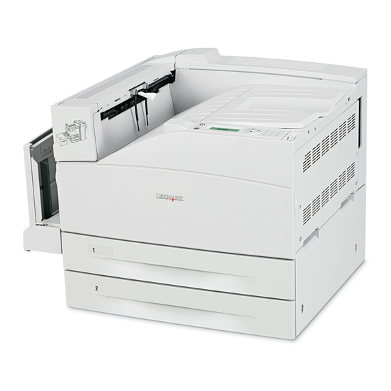
4024-110 Configured model Previous The following illustration shows a fully configured printer. Items denoted with an asterisk (*) are options. Bridge unit* (Used in conjunction Exit 2* with finisher) (Used in conjunction Next with duplex unit) Go Back Operator panel Duplex unit* Finisher* Multipurpose... -
Page 21: Acronyms
4024-110 Previous Acronyms 2 Tray Module Alternate Current ASIC Application Specific Integrated Circuit Next Customer Replaceable Unit Customer Setup Direct Current Go Back DIMM Dual Inline Memory Module DRAM Dynamic Random Access Memory Enhanced Data Out Electrophotographic Process Electrostatic Discharge Field Replaceable Unit Gigabyte Ground Fault Interrupter... - Page 22 4024-110 Previous Next Go Back Printer Service Manual...
-
Page 23: Diagnostic Information
4024-110 2. Diagnostic information Previous Start Next CAUTION—SHOCK HAZARD: Remove the power cord from the electrical outlet and then from the printer before connecting or Go Back disconnecting any cable, assembly, or electronic board. This is a precaution for personal safety and to prevent damage to the printer. -
Page 24: Confirm The Installation Status
4024-110 Previous Confirm the installation status Be sure to check the following items before starting the troubleshooting procedures. • With the power cord unplugged from the wall outlet, check that the cord is free from breakage, short-circuit, Next disconnected wire, or incorrect connection in the power cord. •... -
Page 25: Printer Operator Panel
4024-110 Previous Printer operator panel The printer operator panel consists of these items: • A four-line, backlit, gray-scale display that can show both graphics and test • Eight buttons Next • Indicator light • Numeric pad • USB direct interface Go Back The use of the buttons and the layout of the display panel is described in the following table. - Page 26 4024-110 Previous Item Description Navigation Press the up or down arrow buttons to scroll through menus or menu items, or to increase or decrease a value when entering numbers. Press the left or right arrow buttons to scroll through menu settings (also called Next values or options), or to scroll through text that rolls to another screen.
-
Page 27: Error Code Messages
4024-110 Previous Error code messages Error code or Error contents Description/Action message Next 200.00 Sensor (registration) off The sensor (registration) is not turned off within the jam (too long) specified time after the registration clutch is turned Paper jam Go Back Check area A Go to “200.00 Sensor (registration) off jam (too... - Page 28 4024-110 Previous Error code or Error contents Description/Action message 230.00 Sensor (duplex wait) on jam The sensor (duplex wait) is not turned on within the specified time after the exit2 motor is turned on. Paper jam Refer to Options Service Manual. Next Check areas A, E...
- Page 29 4024-110 Previous Error code or Error contents Description/Action message 243.01 Sensor (tray 3 feed-out) on The sensor (tray 3 feed-out) is not turned on within jam (tray 3 media feed) the specified time after the pre-feed sensor3 is on. Paper jam Refer to Options Service Manual.
- Page 30 4024-110 Previous Error code or Error contents Description/Action message 245.01 Sensor (tray 5 feed-out) on The sensor (tray 5 feed-out) on the printer is not turned on within the specified time after the HCF Paper jam feed lift motor is turned on. Next Check area K Refer to Options Service Manual.
- Page 31 4024-110 Previous Error code or Error contents Description/Action message 282.00 Sensor (finisher media Sensor (finisher media entrance) is not turned on entrance) on jam with the specified time after the sensor (bridge unit Paper jam media exit) is turned on. Next Check area F Refer to Finisher Service Manual.
- Page 32 4024-110 Previous Error code or Error contents Description/Action message 284.02 Sensor (lower media exit) on Sensor (buffer path) is not turned on within the jam B specified time after the sensor (bridge unit media Paper jam entrance) is turned on. Next Check areas At this time, the sensor (finisher media entrance) is...
- Page 33 4024-110 Previous Error code or Error contents Description/Action message 287.03 Sensor (upper media exit) on Sensor (upper media exit) is not turned on within the jam C specified time after the sensor (finisher media Paper jam entrance) is turned on. Next Check area At this time, the sensor (bridge unit media exit) is...
- Page 34 4024-110 Previous Error code or Error contents Description/Action message 288.04 Sensor (diverter gate) Static Paper remains on the sensor (diverter gate) when jam (to stacker bin) A the finisher is in the stacker bin exit mode. Paper jam At this time, the sensor (bridge unit media exit) is Next Check area F turned on.
- Page 35 4024-110 Previous Error code or Error contents Description/Action message PC cartridge end of life The PC cartridge needs to be replaced. Replace PC Go to “PC cartridge end of life” on page 2-69. unit Next PC cartridge life near end The PC cartridge needs to be replaced soon.
- Page 36 4024-110 Previous Error code or Error contents Description/Action message 912.00 PC cartridge unit motor The PC cartridge motor does not rotate at the failure specified speed. Service motor error Go to “912.00 PC cartridge unit motor failure” on Next page 2-48.
- Page 37 4024-110 Previous Error code or Error contents Description/Action message 920.00 Fuser unit assembly on time During the warm-up period, the control thermistor failure does not detect the ready temperature even when Service fuser the specified time is passed after the main lamp is error Next turned on.
- Page 38 4024-110 Previous Error code or Error contents Description/Action message 929.00 Sensor (ATC) failure The sensor (ATC) failed. Service PC Go to “929.00 Sensor (ATC) failure” on cartridge page 2-56. Next 930.00 Laser power failure Light intensity of the LD2 is less than the specified value.
- Page 39 4024-110 Previous Error code or Error contents Description/Action message 945.01 Tray 5 HCF NVM R/W failure A read/write error has occurred on the NVM of the tray 5 HCF controller card assembly. Service tray 5 failure Refer to Options Service Manual. Next 951.XX RIP card assembly NVRAM...
- Page 40 4024-110 Previous Error code or Error contents Description/Action message 981.00 Stacker bin failure The sensor (stacker bin level) is not turned on within the specified period after the stacker bin starts Service rising. finisher error Next Refer to Finisher Service Manual. 981.01 Stacker bin upper limit failure The stacker bin abnormally rises beyond the...
- Page 41 4024-110 Previous Error code or Error contents Description/Action message 985.01 Sensor (punch carriage shift The sensor (punch carriage shift HP) is not turned HP) off failure off even when the specified time passed after the Service punch carriage shift motor assembly is turned on. finisher error Next Or the sensor (punch carriage shift HP) is turned on...
- Page 42 4024-110 Previous Error code or Error contents Description/Action message 990.01 Sensor (stapler carriage HP) The sensor (stapler carriage HP) is not turned off off failure within 500 ms after stapler starts moving to the Service staple position, and sensor (stapler carriage HP) is finisher error Next turned off.
- Page 43 4024-110 Previous Error code or Error contents Description/Action message Close door B Printer left lower door open. The printer left lower door assembly is open. Go to “Printer left lower door open” on page 2-72. Next Close door C 2TM/TTM left door assembly The 2TM/TTM door is open.
- Page 44 4024-110 Previous Error code or Error contents Description/Action message Remove Standard bin 1 full. Media in standard bin 1 is at maximum capacity. paper from Go to “Standard bin 1 full” on page 2-73. standard Next output bin Remove Standard bin 2 full. Media in standard bin 2 is at maximum capacity.
-
Page 45: Service Checks
4024-110 Previous Service checks 200.00 Sensor (registration) off jam (too long) Next Step Check Go Back Check the media position. Remove the Go to step 2. media. Open the printer left door assembly, and visually check it. Does the media touch the sensor (registration)? Check the roll. -
Page 46: Sensor (Registration) Static On Jam
4024-110 200.01 Sensor (registration) static on jam Previous Step Check Check the media position. Remove the Go to step 2. Next media. Open the printer left door assembly, and visually check it. Does the media touch the sensor (registration)? Go Back Check the sensor (registration) for proper operation. - Page 47 4024-110 Previous Step Check Inspect the pinch roll on the transfer roll guide assembly. Go to step 5. Replace the transfer roll guide Is the transfer roll guide assembly free of damage? assembly. Next Go to “Transfer roll guide assembly removal”...
-
Page 48: Sensor (Fuser Exit) Off Jam
4024-110 202.00 Sensor (fuser exit) off jam Previous Step Check Check the media position. Remove the Go to step 3. Next media. Open the printer left door assembly, and visually check it. Go to step 2. Does the media touch the sensor (fuser exit)? Go Back Check the roll. -
Page 49: Sensor (Fuser Exit) Off (Too Short) Jam
4024-110 202.01 Sensor (fuser exit) off (too short) jam Previous Step Check Check the media position. Remove the Go to step 2. Next media. Open the printer left door assembly, and visually check it. Does the media touch the sensor (fuser exit)? Go Back Check the fuser unit assembly for a media jam. -
Page 50: Sensor (Fuser Exit) Static Jam
4024-110 202.02 Sensor (fuser exit) static jam Previous Step Check Check the media position. Remove the Go to step 2. Next media. Open the printer left door assembly, and visually check it. Does the media touch the sensor (fuser exit). Go Back Check the sensor (fuser exit) for operation. - Page 51 4024-110 Previous Step Check Check the drive power transmission. Go to step 5. Replace damaged components. Does the exit 1 media exit roll assembly and the other gears rotate smoothly? Go to “Exit 1 media Next shift assembly removal” on page 4-104.
-
Page 52: Sensor (Exit 2) Off Jam
4024-110 Previous Step Check Check the media diverter solenoid for proper operation. Go to step 13. Go to step 12. 1. Enter Diagnostics mode. 2. Select MOTOR TESTS. Next 3. Select Diverter solenoid. Go Back Open the printer left door assembly. Does the above component operate normally? Check the media diverter solenoid for proper Replace the media... - Page 53 4024-110 Previous Step Check Check the sensor (exit 2) for proper operation. Go to step 8. Go to step 7. 1. Enter Diagnostics mode. 2. Select BASE SENSOR TESTS. Next 3. Select Media Path. 4. Select Exit2. Go Back Does the display on the operator panel change every time the actuator on the above sensor operates? Check the sensor (exit 2) for proper connection.
-
Page 54: Sensor (Pre-Feed) On Jam (Tray 1 Feed)
4024-110 241.00 Sensor (pre-feed) on jam (tray 1 feed) Previous Step Check Check the media condition. Replace the Go to step 2. Next damaged media Is the media in the tray crumpled or damaged? with new. Check the media size setup. Go to step 3. -
Page 55: Sensor (Registration) On Jam (Tray 1 Feed)
4024-110 Previous Step Check Check the media feed lift motor for proper operation of Re-install the Go to step 10. tray 1. media feed lift motor for tray 2 as Replace the media feed lift motor for tray 1 with one from Next it previously was, tray 2. -
Page 56: Sensor (Pre-Feed) On Jam (Tray 2 Feed)
4024-110 Previous Step Check Check the sensor (registration) for proper operation. Go to step 7. Go to step 6. 1. Enter Diagnostics mode. 2. Select BASE SENSOR TEST. Next 3. Select Media path. 4. Select Registration. Go Back Open and check the printer left door assembly. Does the display on the operator panel change every time the sensor actuator operates? Check the sensor (registration) connection. - Page 57 4024-110 Previous Step Check Check the rolls for tray 2. Go to step 4. Clean or replace the feed roll, Remove tray 2, and check it. separation roll, Next and pick roll. Are the feed roll, separation roll, pick roll free of excess wear and contamination? Go to “Feed roll...
-
Page 58: Sensor (Tray 2 Feed-Out) On Jam (Tray 2 Feed)
4024-110 Previous Step Check Check the media feed lift motor in tray 2 for proper Install the media Go to step 10. operation. feed lift motor for tray 1 as it Replace the media feed lift motor for tray 2 with the one Next previously was, from tray 1. - Page 59 4024-110 Previous Step Check Check the sensor (tray 2 feed-out) for proper operation. Go to step 7. Go to step 6. 1. Enter Diagnostics mode. 2. Select INPUT TRAY TESTS. Next 3. Select Sensor test. 4. Select Tray 2. 5. Select Media out. Go Back Open the printer left lower door assembly and check it.
-
Page 60: Sensor (Registration) On Jam (Tray 2 Feed)
4024-110 242.02 Sensor (registration) on jam (tray 2 feed) Previous Step Check Check the media condition. Replace the media Go to step 2. Next with new; ensure it Is the media in the tray, crumpled or damaged? is dry. Check the media size setup. Go to step 3. -
Page 61: Sensor (Tray 2 Feed-Out) Static Jam
4024-110 Previous Step Check Check the sensor (tray 2 feed-out) connection. Replace the Replace the sensor (tray 2 sensor (tray 2 Is the sensor (tray 2 feed-out) properly connected? feed-out). feed-out). Next Go to “Sensor (tray 2 feed-out) removal” on page 4-81. -
Page 62: Sensor (Registration) On Jam (Mpf Pick)
4024-110 250.00 Sensor (registration) on jam (MPF pick) Previous Step Check Check the media condition. Replace the media Go to step 2. Next with new; ensure it Is the media in the MPF tray crumpled or damaged? is dry. Check the media size setup. Go to step 3. -
Page 63: System Software Error
Note: Before troubleshooting, determine the operating system used when the error occured. If possible determine whether a PostScript or PCL file was sent to the device when the error occured. Ask the customer which Lexmark Solutions applications are installed on the device. Step Action and questions POR the device. - Page 64 Reinstall the memory, and send a print job to the Go to step 15. Go to step 16. device. Does the 900.xx error reoccur? Install a Lexmark recommended memory option. Send Go to step 31. Problem a print job to the device. resolved.
- Page 65 4024-110 Previous Step Action and questions Reinstall the modem. Restart the device. Go to step 18. Go to step 20. Does the 900.xx error reoccur? Upgrade the firmware. Contact your next level of Go to step 19. Problem Next support for the correct firmware level to use. resolved.
-
Page 66: Ram Read/Write Check Failure
4024-110 Previous Step Action and questions Contact your next level of support. You will need the following information for them: • Exact 900.xx error digits and complete error message • Printed menu settings page Next • Printed network settings page •... -
Page 67: Nvm Read/Write Cannot Be Executed Failure
4024-110 Previous Step Check Perform a print test. Replace the Problem solved. printer engine card Does the error still occur? assembly. Next Go to “Printer engine card assembly removal” on Go Back page 4-119. 905.00 NVM read/write cannot be executed failure Step Check Perform a POR. -
Page 68: Rfid Asic Failure
4024-110 Previous Step Check Perform a print test. Replace the Problem solved. printer engine card Does the error still occur? assembly. Next Go to “Printer engine card assembly removal” on Go Back page 4-119. 907.00 RFID ASIC failure Step Check Perform a POR. -
Page 69: Transport Motor Stop Failure
4024-110 Previous Step Check Perform a print test. Replace the Problem solved. printer engine card Does the error still occur? assembly. Next Go to “Printer engine card assembly removal” on Go Back page 4-119. 910.00 Transport motor stop failure Step Check Check the dual drive motor assembly installation. -
Page 70: Transport Motor Failure
4024-110 911.00 Transport motor failure Previous Step Check Check the dual drive motor assembly for operation. Go to step 3. Go to step 2. Next Open the rear motor cover, and check it. 1. Enter Diagnostics mode. Go Back 2. Select MOTOR TESTS. 3. -
Page 71: Printhead Assembly Failure
4024-110 Previous Step Check Check the dual drive motor assembly connection. Replace the dual Replace the drive motor connection. Is the dual drive motor assembly properly connected? assembly. Next Perform a print test. Replace the Problem solved. printer engine card Does the error continue? assembly. -
Page 72: Toner Add Motor Assembly Failure
4024-110 914.00 Toner add motor assembly failure Previous Step Check Check the toner cartridge for installation. Problem solved Go to step 2. Next Remove the toner cartridge, and reinstall it. Does it operate properly? Go Back Check the gear rotation for the toner cartridge guide Go to step 3. -
Page 73: Pc Cartridge Cooling Fan Failure
4024-110 Previous Step Check Check the fuser cooling fan for operation. Go to step 5. Go to step 4. 1. Enter Diagnostics mode. 2. Select MOTOR TESTS. Next 3. Select Fuser cooling fan. Go Back Does the fuser cooling fan RPM increase? Check the fuser cooling fan for proper connection. -
Page 74: Sensor (Exit 1 Media Shift Hp) Failure
4024-110 918.00 Sensor (exit 1 media shift HP) failure Previous Step Check Check the sensor (exit 1 media shift HP) for operation. Go to step 3. Go to step 2. Next 1. Enter Diagnostics mode. 2. Select BASE SENSOR TESTS. 3. -
Page 75: Fuser Unit Assembly On Time Failure
4024-110 920.00 Fuser unit assembly on time failure Previous Step Check Check the fuser unit assembly for a media jam. Remove the Go to step 2. Next media. Open the printer left door assembly, and check it. Is there a media jam in the fuser unit assembly? Go Back Leave the printer powered on with the error code displayed Go to step 3. -
Page 76: Center Thermistor Failure
4024-110 922.00 Center thermistor failure Previous Step Check Check the fuser unit assembly for installation. Go to step 2. Install the fuser Next unit assembly Open the printer left door assembly, and check it. securely. Is the fuser unit assembly installed securely? Go Back Check the fuser unit assembly connection. -
Page 77: Pressure Roll Thermistor Failure
4024-110 924.00 Pressure roll thermistor failure Previous Step Check Check the fuser unit assembly for installation. Go to step 2. Install the fuser Next unit assembly Open the printer left door assembly, and check it. securely. Is the fuser unit assembly installed securely? Go Back Check the fuser unit assembly connection. -
Page 78: Pc Cartridge Rfid Data Write Failure
4024-110 927.00 PC cartridge RFID data write failure Previous Step Check Check the PC cartridge installation. Go to step 2. Install the PC Next cartridge properly. Is the PC cartridge properly installed? Check the sensor (RFID PC cartridge) installation. Go to step 3. Install the sensor Go Back (RFID PC... -
Page 79: Laser Power Failure
4024-110 Previous Step Check Check the switch (PC cartridge interlock) connection. Replace the PC Replace the cartridge. connection. Is the switch (PC cartridge interlock) properly connected? Next Perform a print test. Replace the Problem solved. printer engine card Does the error continue? assembly. -
Page 80: Toner Cartridge Rfid Data Write Failure
4024-110 932.00 Toner cartridge RFID data write failure Previous Step Check Check the toner cartridge installation. Go to step 2. Install the toner Next cartridge properly. Is the toner cartridge properly installed? Check the sensor (RFID toner cartridge) installation. Go to step 3. Install the sensor Go Back (RFID toner... -
Page 81: Rip Card Assembly Communication Failure
4024-110 939.00 RIP card assembly communication failure Previous Step Check Perform a POR. Go to step 2. Perform several Next print tests. Does the error occur when the power is turned off/on? If the problem remains, go to Go Back step 2. -
Page 82: Media Tray 2 Lift Up / No Media Tray Failure
4024-110 Previous Step Check Check the tray 1 media feed lift motor for operation. Reinstall the Go to step 7. media feed lift Replace the tray 1 media feed lift motor with the motor from motor for media tray 2. Next tray 2 as it was. - Page 83 4024-110 Previous Step Check Check the tray 2 media feed lift motor for operation. Go to step 9. Go to step 5. Pull out the media tray, and then push it back in. Next Does the motor lift up the tray normally? Check the tray 2 media feed lift motor connection.
-
Page 84: Rip Card Assembly Nvram Failure
4024-110 951.XX RIP card assembly NVRAM failure Previous Step Check Perform a POR. Go to step 2. Perform several Next print tests. Does the error occur when the power is turned off/on? If the problem remains, go to Go Back step 2. -
Page 85: Operator Panel Assembly Nvram Failure
4024-110 953.XX Operator panel assembly NVRAM failure Previous Step Check Perform a POR. Go to step 2. Perform several Next print tests. Does the error occur when the power is turned off/on? If the problem remains, go to Go Back step 2. -
Page 86: Rip Card Assembly Nand Crc Failure
4024-110 955.XX RIP card assembly NAND CRC failure Previous Step Check Perform a POR. Go to step 2. Perform several Next print tests. Does the error occur when the power is turned off/on? If the problem remains, go to Go Back step 2. -
Page 87: Rip Card Assembly Processor Over Temperature Failure
4024-110 956.01 RIP card assembly processor over temperature failure Previous Step Check Perform a POR. Go to step 2. Perform several Next print tests. Does the error occur when the power is turned off/on? If the problem remains, go to Go Back step 2. -
Page 88: Exit Interface Card Assembly Communication Failure
4024-110 980.03 Exit interface card assembly communication failure Previous Step Check Check the exit interface card assembly for proper Go to step 2. Replace the Next connection. connection. Check the connection between the exit interface card Go to step 3. Replace the assembly P430 and the LVPS assembly P526. -
Page 89: No Media In The Select Media Tray
4024-110 Previous Step Check Perform a print test. Replace the Problem solved. printer engine card Does the error continue? assembly. Next Go to “Printer engine card assembly removal” on Go Back page 4-119. No media in the select media tray Step Check Check the media. -
Page 90: Paper Is Installed (Short Edge) In The Media Paper Tray
4024-110 Paper is installed (short edge) in the media paper tray Previous Step Check Is the media installed (short edge) orientation in the media Turn media 90 Go to step 2. Next tray assembly as opposed to long edge? degrees, or enable short edge feeding which is found in the configuration... -
Page 91: Pc Cartridge Rfid Failure
4024-110 PC cartridge end of life Previous Step Check Check the PC cartridge installation. Go to step 2. Install the PC Next cartridge properly. Is the PC cartridge properly installed? Check the sensor (RFID PC cartridge) installation. Go to step 3. Install the sensor Go Back (RFID PC unit) -
Page 92: Pc Cartridge Set Failure
4024-110 PC cartridge set failure Previous Step Check Check the PC cartridge installation. Go to step 2. Install the PC Next cartridge properly. Is the PC cartridge properly installed? Check the PC cartridge sensor connection. Replace the PC Replace the Go Back cartridge connection. -
Page 93: Printer Left Door Open
4024-110 Previous Step Check Check the switch (printer front door interlock) connection. Replace the switch Replace the (printer front door connection. Is the switch (printer front door interlock) properly interlock). connected? Next Go to “Switch (printer front door interlock) removal” on Go Back page 4-5. -
Page 94: Printer Left Lower Door Open
4024-110 Printer left lower door open Previous Step Check Is the printer left lower door assembly opening and closing Go to step 2. Check the printer Next properly? front door assembly for deformation, and reinstall it. Go Back Check the switch (printer front door interlock) for operation. Go to step 4. -
Page 95: Standard Bin 1 Full
4024-110 Standard bin 1 full Previous Step Check Check the actuator for movement. Go to step 2. Reinstall the Next standard bin 1 full Does the standard bin 1 full actuator move up and down actuator. normally? Go Back Check the sensor (standard bin full exit 1) for operation. Go to step 5. -
Page 96: Standard Bin 2 Full
4024-110 Standard bin 2 full Previous Step Check Check the actuator for movement. Go to step 2. Reinstall the Next media weight Does the media weight assembly move up and down assembly. normally? Go Back Check the sensor (standard bin full exit 2) for operation. Go to step 5. - Page 97 4024-110 Previous Step Check Check the pipe, located on the lower part of the toner Go to step 5. Clean the pipe. cartridge for debris. Is the pipe, located on the lower part of the toner cartridge Next guide assembly, clogged? Check the sensor (RFID toner cartridge) for proper Go to step 6.
-
Page 98: Toner Cartridge Near Empty
4024-110 Toner cartridge near empty Previous Step Check Does the toner cartridge contain toner? Go to step 2. Replace the toner Next cartridge. Check the toner cartridge for proper installation. Problem solved. Go to step 3. Go Back Remove the toner cartridge, and reinstall it. Does it install properly? Check the gear rotation in the toner cartridge guide Go to step 4. -
Page 99: Toner Cartridge Rfid Failure
4024-110 Previous Step Check Checking the sensor (RFID toner cartridge) connection. Replace the Replace the sensor (RFID connection. Is the sensor (RFID toner cartridge) properly connected? toner cartridge). Next Perform a print test. Replace the Problem solved. printer engine card Does the error continue? assembly. -
Page 100: Tray 1 Media Size Failure
4024-110 Previous Step Check Check the toner cartridge guide assembly. Replace the toner Go to step 4. cartridge. Remove the top cover assembly. Go to “Toner Next Is the toner cartridge guide assembly damaged? cartridge guide assembly removal” on page 4-93. -
Page 101: Tray 2 Media Size Failure
4024-110 Tray 2 media size failure Previous Step Check Check the media. Go to step 2. Load media Next properly. Is media loaded, in media tray 2, properly? Pull out media tray 2, and visually check it. Go Back Check the media. Go to step 3. - Page 102 4024-110 Previous Step Check Check the roll for tray 1 Go to step 6. Clean or replace the feed roll, Pull out tray 1, and check it. separation roll, Next and pick roll. Is the feed roll, separation roll, and pick roll free of excess wear and contamination? Check the media position Remove the...
-
Page 103: Tray 2 Media Size Mismatch In Length
4024-110 Previous Step Check Perform a print test Replace the Problem solved. printer engine card Does the error continue? assembly. Next Go to “Printer engine card assembly removal” on Go Back page 4-119. Tray 2 media size mismatch in length Step Check Check the media. - Page 104 4024-110 Previous Step Check Check the roll. Go to step 8. Clean or replace the transport roll Open the printer left door assembly, and check it. assembly. Next Is the transport roll assembly free of excess wear and Go to “Transfer contamination? roll assembly...
-
Page 105: Image Quality Trouble
4024-110 Previous Image quality trouble Troubleshooting Note: First, get a printout as a base, follow the symptom table to identify the possible failing FRUs. Next Image quality symptoms: Go Back • Faint print (low contrast) “Faint print (Low contrast)” on page 2-84. -
Page 106: Image Quality
4024-110 Image Quality Previous Faint print (Low contrast) Next Go Back Before starting, check the media route for foreign objects, such as staples, clips, and scraps, in the media path. Step Check Check the media condition. Problem solved. Go to step 2. Load new, dry, recommended media, and perform a print test. - Page 107 4024-110 Previous Step Check Check the image development process. Go to step 7. Go to step 9. Perform a print test. Turn off the printer power while Next printing. Carefully remove the PC cartridge, and check the developed image formed on the drum right before the transfer roll assembly.
- Page 108 4024-110 Blank print (no print) Previous Next Go Back Check the media path for foreign objects such as staples, clips, and scraps of media. Step Check Check the toner cartridge. Problem solved. Go to step 2. Install a new toner cartridge. Re-print the defective image.
- Page 109 4024-110 Previous Step Check Check the printhead installation. Go to step 8. Go to step 7. Is the printhead assembly installed securely with four Next screws? Check the printhead assembly installation. Problem solved. Go to step 8. Install the printhead assembly securely and perform a Go Back print test.
- Page 110 4024-110 Solid black Previous Next Go Back Check the media path for foreign objects such as staples, clips, scraps of media. Step Check Check the toner cartridge. Problem solved. Go to step 2. Install a new toner cartridge. Re-print the defective image. Is the image density normal? Check connector JHAB1 on the RIP card assembly.
- Page 111 4024-110 Vertical blank lines (white stripes in media transport direction) Previous Leading edge Next Go Back Trailing edge Step Check Check the media condition. Go to step 2. Problem solved. Load new, dry, recommended media. Re-print the defective image. Does the error continue? Are the media transfer route and the media path clear of Go to step 3.
- Page 112 4024-110 Previous Step Check Check the heat roll and pressure roll. Replace the fuser Go to step 9. unit assembly. Remove the fuser unit assembly. Next Is there contamination or cracking on the heat roll or pressure roll? Check the printer engine card assembly. Go to step 10.
- Page 113 4024-110 Horizontal band printheads out Previous Leading edge Next Go Back Trailing edge Step Check Check the media condition. Go to step 2. Problem solved. Load new, dry, and recommended media. Re-print the defective image. Does the error continue? Are the media transfer route and the media path free of Go to step 3.
- Page 114 4024-110 Previous Step Check Check the image transfer process. Go to step 10. Go to step 9. Check the toner image formed on the drum after the Next transfer roll assembly passed. Is the toner image completely transferred on the media? Check the HVPS card assembly.
- Page 115 4024-110 Vertical stripes Previous Leading edge Next Go Back Trailing edge Step Check Check the media condition. Go to step 2. Problem solved. Load new, dry, recommended media. Re-print the defective image. Does the error continue? Are the media transfer route and the media path free of Go to step 3.
- Page 116 4024-110 Previous Step Check Check the laser beam route. Go to step 8. Remove debris, or clean the Check for debris between the transfer roll assembly and transfer roll Next the PC drum. assembly window. Check the printhead assembly window for contamination.
- Page 117 4024-110 Horizontal stripes Previous Leading edge Next Go Back Trailing edge Step Check Check the media condition. Go to step 2. Problem solved. Load new, dry, recommended media. Re-print the defective image. Does the error continue? Check the media transfer route. Go to step 3.
- Page 118 4024-110 Previous Step Check Check the image transfer process. Go to step 9. Go to step 10. Check the toner image formed on the drum after the Next transfer roll assembly passed. Is the toner image completely transferred on the media? Check the HVPS.
- Page 119 4024-110 Partial lack Previous Leading edge Next Go Back Trailing edge Step Check Check the media condition. Go to step 2. Problem solved. Load new, dry, recommended media. Re-print the defective image. Does the error continue? Check the media transfer route. Go to step 3.
- Page 120 4024-110 Spots Previous Leading edge Next Go Back Trailing edge Step Check Check the media condition. Go to step 2. Problem solved. Load new, dry, recommended media. Re-print the defective image. Does the error continue? Check the media transfer route. Go to step 3.
- Page 121 4024-110 After image Previous Leading edge Next Go Back Trailing edge The ghost appears on the media which may be the image from the previous page, or part of the page currently printing. Step Check Check the media condition. Go to step 2. Problem solved.
- Page 122 4024-110 Background (fog) Previous Leading edge Next Go Back Trailing edge Step Check Check the media condition. Go to step 2. Problem solved. Load new, dry, recommended media. Re-print the defective image. Does the error continue? Check the media transfer route. Go to step 3.
- Page 123 4024-110 Previous Step Check Check the printer engine card assembly. Replace the RIP Problem solved. card assembly. Replace the printer engine card assembly. Next Go to “RIP card Perform a print test. assembly removal” on Does the error continue? page 4-126.
- Page 124 4024-110 Skew Previous Leading edge Next Go Back Trailing edge The printed image is not paralleled with both sides of the media. Step Check Check printer installation placement. Go to step 2. Correct the installation Check the installation surface for irregularities. placement.
- Page 125 4024-110 Media damage Previous Leading edge Next Go Back Trailing edge Step Check Check printer installation placement. Go to step 2. Correct the installation Check the installation surface for irregularities. placement. Check for missing printer foot. Is the setup surface normal? Check the media feed.
- Page 126 4024-110 No fuse Previous Leading edge Next Go Back Trailing edge Step Check Check the fuser unit assembly installation. Go to step 2. Problem solved. Check that the levers, on both sides of the fuser unit assembly, are pushed down. Re-print the defective image.
- Page 127 4024-110 Previous Step Check Check the printer engine card assembly. Replace the RIP Problem solved. card assembly. Replace the printer engine card assembly. Next Go to “RIP card Perform a print test. assembly removal” on Does the error continue? page 4-126.
- Page 128 4024-110 Previous Next Go Back 2-106 Printer Service Manual...
-
Page 129: Diagnostic Aids
4024-110 3. Diagnostic aids Previous This chapter explains the tests and procedures to identify printer failures and verify repairs have corrected the problem. Next Diagnostics are built into the printer RIP card assembly and can be accessed from the printer operator panel. Go Back Accessing service menus There are different test menus that can be accessed during POR to identify problems with the printer. -
Page 130: Diagnostics Mode
4024-110 Previous Diagnostics mode Entering Diagnostics mode Next Press and hold Turn on the printer. Release the buttons when Performing Self Test displays. Go Back Available tests The tests display on the operator panel in the order shown: Diagnostics mode tests MOTOR TESTS “MOTOR TESTS”... - Page 131 4024-110 Diagnostics mode tests (continued) Previous HARDWARE TESTS Panel Test “Panel Test” on page 3-6. Button Test “Button Test” on page 3-6. Next DRAM Test “DRAM Test” on page 3-7. CACHE Test DUPLEX TESTS (if installed) Go Back Quick Test “Quick Test (duplex)”...
-
Page 132: Exiting Diagnostics Mode
4024-110 Exiting Diagnostics mode Previous Select Exit Diagnostics to exit the Diagnostics mode. Resetting the Printer displays, the printer performs a POR, and returns to normal mode. Next Go Back Printer Service Manual... -
Page 133: Motor Tests
4024-110 MOTOR TESTS Previous The tests in this group allow you to test specific motors, and on some motors run them forward or reverse. To run the MOTOR TESTS: Next Select MOTOR TESTS from DIAGNOSTICS. Select the test to run. The following tests are available: Go Back •... -
Page 134: Hardware Tests
4024-110 Print quality pages (Prt Quality Pgs) Previous The purpose of this diagnostic function is to allow printing of the print quality test pages with the toner cartridge lockout function disabled. The print quality pages consists of four pages. Page one contains a mixture of graphics and text. - Page 135 4024-110 DRAM Test Previous The purpose of this test is to check the validity of DRAM memory, both standard and optional. The test writes patterns of data to DRAM to verify that each bit in memory can be set and read correctly. To run the DRAM Test: Next Select HARDWARE TESTS from DIAGNOSTICS.
-
Page 136: Duplex Tests
4024-110 DUPLEX TESTS Previous Only displayed if a duplex option is installed. Quick Test (duplex) Next This test prints a duplex version of the Quick Test that can be used to verify that the correct placement of the top margin on the back side of a duplex page. You can run one duplexed page (Single), or continue printing duplexed pages (Continuous) until Stop ( ) is pressed. -
Page 137: Input Tray Tests
4024-110 INPUT TRAY TESTS Previous Feed Tests (input tray) This test lets the servicer observe the paper path as media is feeding through the printer. A blank sheet of paper feeds through the printer as the laser turns off during this test. The only way to observe the paper path is to open Next the lower front door that is used to access the envelope or multipurpose feeder. -
Page 138: Output Bin Tests
4024-110 OUTPUT BIN TESTS Previous Feed Tests (output bins) Use these tests to verify that media can be fed to a specific output bin. Media is fed from the default input source to the selected output bin. No information is printed on the media fed to the output bin because the printhead is Next not engaged during this test. -
Page 139: Finisher Tests
4024-110 Each of the tests categories includes the individual sensors that can be manually actuated, and the display Previous shows Open or Closed. • Standard Bin Std bin full exit1 Std bin full exit2 • Next Output Bin 1 Fin upper bin full •... - Page 140 4024-110 Sensor Test (finisher) Previous This test can be used to verify whether or not the finisher sensors are working correctly. To run the finisher Sensor Test: Select FINISHER TESTS from DIAGNOSTICS. Next Select Sensor Test from FINISHER TESTS. Select one of the test categories: •...
-
Page 141: Base Sensor Test
4024-110 • Punch and Staple Previous Punch side reg1 Punch side reg2 Punch box set Punch waste full Low staple Next Punch carriage shift hp Punch unit hp Stapler carriage shift hp Go Back Punch cam front Punch hole select Press Back ( ) or Stop ( ) to exit the test. -
Page 142: Device Tests
4024-110 DEVICE TESTS Previous Quick Disk Test This test performs a non-destructive read/write on one block per track on the disk. The test reads one block on each track, saves the data, and proceeds to write and read four test patterns to the bytes in the block. If the Next block is good, the saved data is written back to the disk. -
Page 143: Printer Setup
4024-110 Flash Test Previous This test verifies the functioning of the flash device by writing and reading data on the flash to test the flash. Warning: This test destroys all data on the flash, because the flash is unformatted at the end of the test. To reformat the flash, the servicer or the user must use FORMAT FLASH from the UTILITIES MENU. - Page 144 4024-110 Serial Number Previous The serial number can only be viewed and cannot be changed. To view the serial number: Select PRINTER SETUP from DIAGNOSTICS. Next Select Serial number from PRINTER SETUP. Press Back ( ) to return to PRINTER SETUP. Go Back Engine Setting 1 through 16 Warning: Do not change these settings unless requested to do so by your next level of support.
-
Page 145: Event Log
• Time and date stamps • Page counts for most errors • Additional debug information in some cases The printed event log can be faxed to Lexmark or your next level of support for verification or diagnosis. 3-17 Diagnostic aids... -
Page 146: Exit Diagnostics
4024-110 To print the event log: Previous Select EVENT LOG from DIAGNOSTICS. Select Print Log from EVENT LOG. Press Back ( ) to return to EVENT LOG. Next Clear Log Use Clear Log to remove the current information in the Event Log. This affects both the viewed log and the Go Back printed log information. -
Page 147: Configuration Menu (Config Menu)
4024-110 Previous Configuration menu (CONFIG MENU) Entering Configuration Menu Turn off the printer. Next Press and hold Turn on the printer. Release the buttons when Performing Self Test displays. Go Back The message CONFIG MENU displays on the top line of the operator panel. Available menus Configuration Menu Maint Cnt Value... -
Page 148: Maintenance Page Count (Maint Cnt Value)
4024-110 Configuration Menu (continued) Previous Tray Low Message “Tray Low Message” on page 3-25. Exit Config Menu “Exit Config Menu” on page 3-25. Some menus are not available, depending on the configuration of the printer. Next Maintenance page count (Maint Cnt Value) Go Back The current value for the maintenance page counter is displayed. -
Page 149: Registration
4024-110 REGISTRATION Previous Print registration makes sure the printing is properly aligned on the page. This setting allows separate Left Margin settings for each media tray. (The Top Margin setting is the same for all trays.) Incorrect Next Go Back Registration line Correct... -
Page 150: Print Quality Pages (Prt Quality
4024-110 Quick Test Previous The Quick Test contains the following information: • Print registration settings • Alignment diamonds at the top and bottom Next • Horizontal lines to check for skew • General printer information, including current page count, installed memory, serial number, and code level. To print the Quick Test page: Go Back Note: Print the Quick Test Page on letter or A4 paper. -
Page 151: Size Sensing
4024-110 SIZE SENSING Previous This setting controls whether the printer automatically registers the size of paper installed in an input source with size sensing. Size sensing Next Paper source Length Width ✓ Multipurpose feeder (integrated MPF) Go Back ✓ ✓ Tray 1 (integrated 500-sheet drawer) ✓... -
Page 152: Ppds Emulation
4024-110 PPDS Emulation Previous This menu item allows the user to enable or disable PPDS emulation datastream. When this setting is enabled, the following settings are also changed: • SmartSwitch settings for each port are turned off. Next • The printer language is changed to PPDS Emulation. Users can still switch languages on the operator panel and through the PJL datastream. -
Page 153: Env Prompts
4024-110 Env Prompts Previous This setting controls the tray the user is directed to refill when specific envelope size is out. The selections are Auto (default), MP Feeder, and Manual Env. Jobs On Disk Next If the hard disk is installed, Jobs On Disk allows the user to delete buffered jobs saved on the disk. The values are Delete and Do Not Delete. -
Page 154: Analyzing The Print Test
4024-110 Previous Analyzing the Print Test Print Tests provide several uses in troubleshooting the printer problems. • Isolating problems to either the print engine (printer engine card assembly) or to the RIP card Next assembly and host software. • Locating feed and media transport problems. •... -
Page 155: Driving Force Transmission Path
4024-110 Driving force transmission path Previous Transport motor The rotating force of the transport motor is transmitted through the gear and the pulley (25 tooth) to components that need mechanical driving force as shown in the following diagram. Next Media transport motor Go Back Transport/MPF idler gear 21T/21T Pulley25T... -
Page 156: Media Transport
4024-110 Media transport Previous Media transport path Media is supplied from the MPF, tray 1 or tray 2, and is transported to the printer along the media transport path shown below. Next Tray 2 Tray 1 Go Back Pick roll Pick roll MPF pick roll MPF Transport Roll ASM... - Page 157 4024-110 Media transport path layout Previous The following is a cross section of the laser printer, showing main components directly associated with the media path and transport. Main components associated with transport of media Next Exit 2 media exit roll ASM Exit 2 media exit pinch rolls Go Back Exit 2...
-
Page 158: Functions Of Main Components
4024-110 Functions of main components Previous • Media tray assembly • Media feed unit assembly • • Xerographics Next • Fuser • Drive • Electrical components and rolls Go Back Media tray assembly It is necessary to adjust the front media tray guide assembly, rear media tray guide and media tray end guide of the media tray assembly to match the media size. - Page 159 4024-110 Media tray assembly Previous Media end guide Rear media tray guide Next Go Back Bottom plate Front media tray guide assembly Detection of media size The media size set for the media tray assembly is transmitted to the switch (media size) by moving these guides. The media size is detected by the on/off information of these switches.
- Page 160 4024-110 Sensor (media level) Previous This sensor detects by the actuator position whether media in the media tray assembly is lifted. When the flag of the actuator unblocks the sensing area of the sensor (media level), the sensor detects that the media has been lifted.
-
Page 161: Multi-Purpose Feeder (Mpf)
4024-110 Multi-purpose feeder (MPF) Previous The MPF is a mechanical unit suppling media to the printer. The driving force from the transport motor of the dual drive motor assembly is transmitted to the MPF feed roll to feed media. MPF pick roll Next The MPF pick roll feeds media set on the MPF. -
Page 162: Detecting Media Size
4024-110 Detecting media size Previous The size of media on the MPF is transmitted by moving the MPF side guide, and is determined by the printer engine card assembly. Media sizes that can be automatically detected are as follows: Next Media size Width (mm) Feed length (mm) -
Page 163: Transfer Roll Assembly
4024-110 Transfer roll assembly Previous The transfer roll assembly is driven by direct contact with the drum of the PC cartridge. The transfer roll assembly applies positive charges to the rear surface of the media when the media passes between the transfer roll assembly and the drum. The negatively charged toner image is attracted by positive Next charges on the rear surface of the media. - Page 164 4024-110 process direction (from top to bottom) is determined by the rotational speed of the printhead motor. (The higher Previous the scanning speed becomes, the sooner the scanning of the next row can be started.) Conceptual diagram of an image created by scanning Next Go Back SOS card ASM...
-
Page 165: Fuser
4024-110 Fuser Previous Heat roll The heat roll is a hollow metal tube with a coated surface. This tube is heated by the inner heater lamp. The heat is applied to the media passing between the heat roll and pressure roll, fusing the toner on the media. Next Pressure roll Go Back... - Page 166 4024-110 Fuser exit sensor Previous The fuser exit sensor detects the arrival of media at the detection point in the exit area of the fuser, and also detects the ejection of media from this point. Rear thermistor Center thermistor Next Pressure roll thermistor Pressure roll Go Back...
-
Page 167: Exit
4024-110 Exit Previous Exit 1 ejects printed media from the printer to the standard bin 1. With the optional exit 2 installed, it is also possible to eject media to the standard bin 2 by changing the orientation of the diverter gate on the exit 1. Dual drive motor assembly Next Drives the exit 1 media exit roll assembly that feeds media to each bin. -
Page 168: Drive
4024-110 Drive Previous Media transport motor The media transport motor is a DC brushless motor that drives the exit 1 media exit shaft assembly, fuser assembly, registration roll assembly, and transport roll assembly. Next PC cartridge motor Go Back The PC cartridge motor is a DC brushless motor that drives the PC cartridge, mag roll, and transfer roll assembly. -
Page 169: Electrical Components And Controller
4024-110 Electrical components and controller Previous Switch (main power) Turning on/off the switch, power supplies/cuts off the main power of the printer. Next Finisher AC output Supplies power to the finisher from the main LVPS (low voltage power supply) card assembly. Go Back Switch (printer front door interlock) and switch (printer left door interlock) The switch is a safety switch to cut off a 24 VDC power supply from the LVPS card assembly to the high volt... - Page 170 4024-110 Registration roll assembly Previous The registration roll assembly feeds media from all trays to the PC cartridge and fuser. Switch (PC cartridge interlock) Switch (main power) Next Switch (printer front Switch door interlock) (printer left door Go Back interlock) Fuser cooling fan RIP card ASM Switch (printer left...
-
Page 171: Control
4024-110 Previous Control Media size control Media tray assembly feeding Next The following table gives the states (on/off) of the switches on the switch (media size), corresponding to the media sizes of the media tray assembly. Go Back Note: The switches on the switch (media size) are denoted by “S/W2”, “S/W4”, “S/W3”, “S/W5”, and “S/W1” respectively from the left side. -
Page 172: Printhead Control
4024-110 Printhead control Previous Rotation of printhead motor The on/off control of the printhead motor is performed according to the mode of operation as shown below. Next Operation mode PRINTHEAD motor on/off Standby mode Always off Go Back Print mode Turns on upon receiving the signal from the controller, and turns off after a preset time has passed from the end of printing. -
Page 173: Xerographic Process During A Print Cycle
4024-110 Xerographic Process During a Print Cycle Previous Next Go Back 3-45 Diagnostic aids... - Page 174 4024-110 Charge Previous The Charge Roll places a uniform negative electrostatic charge on the surface of the drum. The drum surface is made of a photoconductive material that holds an electrical charge as long as the drum remains in darkness. Light striking the drum discharges the surface charge.
- Page 175 4024-110 The charge roll is a conductive roll that is positioned slightly above the surface of the drum. The HVPS supplies Previous the charge roll with two voltages; a negative DC charge voltage and an AC discharge voltage that is used for electrically cleaning the drum (discussed in Step 6.
- Page 176 4024-110 The Printhead also helps to clean and prepare the drum by scanning the surface of the drum at the beginning of Previous each individual printer cycle. This action discharges a residual DC charge that may still remain on the Drum from the last print cycle.
- Page 177 4024-110 The toner adhering to the Magnet Roll is always in contact with the drum surface. When a less negative point on Previous the drum (a discharged area) comes in contact with the more negative charged toner on the Magnet Roll, toner transfers from the Magnet Roll to that point on the drum.
- Page 178 4024-110 Transfer Previous As the paper travels between the Transfer Roll and the drum surface, the Transfer Roll applies a positive charge to the back of the printing paper. This positive charge transfers the negative charged toner image from the drum surface to the top surface of the paper.
- Page 179 4024-110 Cleaning Previous The Cleaning Blade removes any toner that remains on the drum after the transfer process. The toner that the Cleaning Blade removes is collected inside the sealed PC Cartridge and reused. Next Go Back Discharge At both the start and the end of each individual printer cycle, the HVPS supplies the charge roll with an AC voltage that is used to electrically clean the drum.
-
Page 180: Safety System Diagram
4024-110 Previous Safety system diagram Fuser cooling fan Switch Switch Switch Printhead (PC Cartridge (Printer front (Printer left Next Printhead interlock) door interlock) door interlock) Dual drive motor ASM motor PC cartridge Transport motor motor Go Back Printer engine card ASM Printhead motor Fuser cooling... - Page 181 4024-110 Print defects guide (PDF) insert here: Previous Next Go Back 3-53 Diagnostic aids...
-
Page 182: Repeating Defects
4024-110 Previous Repeating defects Roll Pitch Transfer roll 59 mm Next Registration roll 44 mm Fuser pressure roll 94 mm Fuser heat roll 79 mm Go Back Charge roll 44 mm PC drum 94 mm 3-54 Printer Service Manual... -
Page 183: Repair Information
4024-110 4. Repair information Previous Warning: Read the following before handling electronic parts. Next Handling ESD-sensitive parts Go Back Many electronic products use parts that are known to be sensitive to electrostatic discharge (ESD). To prevent damage to ESD-sensitive parts, use the following instructions in addition to all the usual precautions, such as turning off power before removing logic boards: •... -
Page 184: Removal Procedures
4024-110 Previous Removal procedures CAUTION—SHOCK HAZARD: Remove the power cord from the electrical outlet and then from the printer before connecting or Next disconnecting any cable, assembly, or electronic board. This is a precaution for personal safety and to prevent damage to the printer. Disconnect any connections between the printer and PCs/ peripherals. -
Page 185: Printer Front Left Cover Removal
4024-110 Printer front left cover removal Previous Note: First, remove the exit 2 unit assembly, if equipped. Refer to the Options Service Manual. Open the printer front door assembly (A). Remove the screw securing the front left cover (B) to the machine. Next Remove the front left cover (B). -
Page 186: Top Rear Cover Removal
4024-110 Top rear cover removal Previous Remove the cable hookup cover. “Cable hookup door removal” on page 4-13. Remove the two screws securing the rear motor cover (A). Open and remove the rear motor cover (A). Remove the screw securing the top rear cover (B). Next Remove the top rear cover (B) by sliding it left in the direction of the arrow, then lift up. -
Page 187: Switch (Printer Front Door Interlock) Removal
4024-110 Switch (printer front door interlock) removal Previous Note: First, remove the bridge unit and the finisher, if equipped. Refer to the Finisher Service Manual. Remove the top cover assembly. Go to “Top cover assembly removal” on page 4-7. Remove the printer front door assembly. Go to “Printer front door assembly removal”... -
Page 188: Operator Panel Assembly Removal
4024-110 Operator panel assembly removal Previous Warning: In the event of replacement of any one of the following components: • Operator panel assembly • RIP card assembly Next Replace only one component at a time. Replace the required component, and perform a POR before replacing a second component listed above. -
Page 189: Top Cover Assembly Removal
4024-110 Top cover assembly removal Previous Note: First, remove the bridge unit and the finisher, if equipped. Remove the operator panel assembly. See “Operator panel assembly removal” on page 4-6. Remove the printer front door assembly. See “Printer front door assembly removal” on page 4-8. -
Page 190: Printer Front Door Assembly Removal
4024-110 Printer front door assembly removal Previous Open the printer front door assembly (A). Remove the front door support strap (B) securing the printer front door assembly (A) to the printer by releasing the plastic hook. With the front door support strap (B) disconnected, place the printer front door assembly (A) in the lower Next most position. -
Page 191: Front Door Support Strap And Front Door Magnetic Catch Removal
4024-110 Front door support strap and front door magnetic catch removal Previous Remove the printer front door assembly. See “Printer front door assembly removal” on page 4-8. Remove the screw securing the front door support strap (A) to the printer front door assembly (B). Remove the front door support strap (A). -
Page 192: Front Inner Cover Removal
4024-110 Front inner cover removal Previous Remove the top cover assembly. See “Top cover assembly removal” on page 4-7. Remove the printer front door assembly. See “Printer front door assembly removal” on page 4-8. Remove the front left cover. See “Printer front left cover removal”... -
Page 193: Right Upper Cover Removal
4024-110 Right upper cover removal Previous Note: First, remove the bridge unit, finisher and finisher docking bracket, if equipped. Remove the two screws securing the right upper cover (A). Move the upper edge of the right upper cover (A) downward and outward as shown by the arrow. Next Move the lower edge of the right upper cover (A) downward to release the right upper cover (A). -
Page 194: Right Lower Cover Removal
4024-110 Right lower cover removal Previous Remove the right upper cover. See “Right upper cover removal” on page 4-11. Pull out media Tray 1 and media Tray 2. Remove the right lower cover (A) by lifting it upward then outward. Note: The right lower cover may take some force to remove. -
Page 195: Cable Hookup Door Removal
4024-110 Cable hookup door removal Previous Open the cable hookup door (A). Slightly lift the top rear cover (B) upward in the direction of the arrow on its outer edge to release the upper boss on the cable hookup door (A). Release the lower boss from the option hookup door (A). -
Page 196: Rear Motor Cover Removal
4024-110 Rear motor cover removal Previous Remove the rear RIP card cover. See “Rear RIP card cover removal” on page 4-125. Remove the two screws securing the rear motor cover (A). Open the rear motor cover (A) by swinging it outward in the direction of the arrow. Remove the rear motor cover (A). -
Page 197: Rear Lower Cover Removal
4024-110 Rear lower cover removal Previous Remove the rear RIP card cover. See “Rear RIP card cover removal” on page 4-125. Remove the rear motor cover. See “Rear motor cover removal” on page 4-14. Remove the two screws securing the rear lower cover (A). Remove the rear lower cover (A). -
Page 198: Option Hookup Cover Removal
4024-110 Option hookup cover removal Previous Remove the option hookup cover (A) from the rear lower cover (B) by moving it outward in the direction of the arrow. Next Go Back 4-16 Printer Service Manual... -
Page 199: Switch (Media Size) Removal
4024-110 Switch (media size) removal Previous Note: This procedure can be applied to tray 1 or tray 2 switch (media size). Remove media Tray 1 and media Tray 2. Remove the screw securing the switch (media size) (A) to the bracket (B) inside the machine. Next Remove the connector from switch (media size) (A). -
Page 200: Media Feed Unit Assembly 1 Removal
4024-110 Media feed unit assembly 1 removal Previous Remove the MPF rear cover. See “MPF rear cover removal” on page 4-55. Remove the MPF feed unit assembly. See “MPF feed unit assembly removal” on page 4-51. Remove printer left door assembly. See “Printer left door support strap removal”... - Page 201 4024-110 Release the plastic bosses on both ends of the vertical turn mylar guide (A). Previous Remove the vertical turn mylar guide (A). Warning: The vertical turn mylar guide will take extra force to remove. Be careful not to damage it. Release the harness from the plastic clamps on the machine.
- Page 202 4024-110 Remove the two screws securing the media feed unit assembly (B). Previous Remove the media feed unit assembly (B) in the direction of the arrow. Clamp Next Go Back Front 4-20 Printer Service Manual...
-
Page 203: Media Feed Unit Assembly 2 Removal
4024-110 Media feed unit assembly 2 removal Previous Remove the MPF rear cover. See “MPF rear cover removal” on page 4-55. Remove the MPF feed unit assembly. See “MPF feed unit assembly removal” on page 4-51. Remove the printer left door assembly. See “Printer left door support strap removal”... - Page 204 4024-110 Release the plastic bosses on both ends of the vertical turn guide (A). Previous Remove the vertical turn guide (A). Next Go Back Left 4-22 Printer Service Manual...
- Page 205 4024-110 Release the harness from the plastic clamps on the machine. Previous Disconnect the harness connector from the machine. Remove the two screws securing the media feed assembly (B). Remove the media feed assembly (B) in the direction of the arrow. Clamp Next Go Back...
-
Page 206: Media Tray Side Guides Removal
4024-110 Media tray side guides removal Previous Remove the media tray. Remove the two e-rings securing the metal bottom plate (A) to the media tray using a small prying tool. Push the front hinge point (B) in the direction of the arrow to release the front boss from the metal bottom plate (A). - Page 207 4024-110 Remove the two screws securing the two pinion gears (C) to the media tray. Previous Remove the pinion gears (C). Remove the front media guide assembly (D) and the rear media guide (E) by sliding them toward the center of the media tray assembly, and lifting up. Next Go Back Front...
- Page 208 4024-110 Note: Before reinstalling the pinion gears (C), slide the front media tray guide assembly (D) and the rear media Previous guide (E) to their outermost positions. Ensure the media side guides slide smoothly. Next Go Back Front 4-26 Printer Service Manual...
-
Page 209: Media Tray End Guide Removal
4024-110 Media tray end guide removal Previous Remove the media tray. Remove the media tray side guides. See “Media tray side guides removal” on page 4-24. Remove the media side guide actuator (A). Next Front Go Back Hole Hook Lock lever Square hole 4-27 Repair information... - Page 210 4024-110 Turn the media tray assembly upside down, and remove the screw and the two hooks securing the Previous actuator link (B) to the media tray. Release the boss on the media end guide actuator (C) from the hole in the actuator link (B) by moving the link in the direction of the arrow.
-
Page 211: Media Tray Lift Gear Group Removal
4024-110 Media tray lift gear group removal Previous Remove the media tray from the machine. Remove the two screws securing bracket (A). Remove the bracket (A). Remove the tray lift coupling gear 13 tooth (B) from bracket (A). Next Remove the tray lift gear 13/60 tooth (C) from bracket (A). Go Back Rear Note: Extra force is required to pull the tray lift coupling gear 13 tooth (B) and the tray lift gear 13/60 tooth (C) -
Page 212: Media Feed Lift Motor Removal
4024-110 Media feed lift motor removal Previous Remove the media feed unit. See “Media feed unit assembly 1 removal” on page 4-18 “Media feed unit assembly 2 removal” on page 4-21. Disconnect the harness from the media feed lift motor (A). Remove the two screws securing the media feed lift motor (A) to the media feed unit assembly (B). -
Page 213: Tray Lift Coupling Assembly Removal
4024-110 Tray lift coupling assembly removal Previous Remove the MPF rear cover. See “MPF rear cover removal” on page 4-55. Remove the MPF feed unit assembly. See “MPF feed unit assembly removal” on page 4-51. Remove the printer left door. See “Printer left door support strap removal”... -
Page 214: Tray Lift One Way Clutch / Gear Assembly Removal
4024-110 Tray lift one way clutch / gear assembly removal Previous Remove the media feed unit assembly. Go to “Media feed unit assembly 1 removal” on page 4-18 “Media feed unit assembly 2 removal” on page 4-21. Remove the harness from the bracket (A). Remove the three screws securing the bracket (A) to the media feed unit assembly. - Page 215 4024-110 Remove the tray lift one-way gear 24 tooth (C). Previous Harness Next Go Back Washer Rear Note: Before reinstalling, ensure all gears and washers are securely attached to the bracket (A). 4-33 Repair information...
-
Page 216: Media Feed Unit Drive Gear - 13 Tooth Removal
4024-110 Media feed unit drive gear - 13 tooth removal Previous Remove the appropriate media feed unit assembly. See “Media feed unit assembly 1 removal” on page 4-18 “Media feed unit assembly 2 removal” on page 4-21. Remove the harness from the bracket (A). Remove the three screws securing the bracket (A) to the media feed unit assembly. -
Page 217: Media Out Actuator Removal
4024-110 Media out actuator removal Previous Remove the appropriate media feed unit assembly. See “Media feed unit assembly 1 removal” on page 4-18 “Media feed unit assembly 2 removal” on page 4-21. Remove the two bosses on the media out actuator (A) to the media feed unit assembly. Remove the media out actuator (A). -
Page 218: Sensor (Media Level) Removal
4024-110 Sensor (media level) removal Previous Remove the appropriate media feed unit assembly. See “Media feed unit assembly 1 removal” on page 4-18 “Media feed unit assembly 2 removal” on page 4-21. Disconnect the connector from the sensor (media level) (A). Release the hooks securing the sensor (media level) (A) to the media feed unit. -
Page 219: Sensor (Media Out) Removal
4024-110 Sensor (media out) removal Previous Remove the appropriate media feed unit assembly. See “Media feed unit assembly 1 removal” on page 4-18 “Media feed unit assembly 2 removal” on page 4-21. Remove the media out actuator. See “Media out actuator removal” on page 4-35. -
Page 220: Sensor (Pre-Feed) Removal
4024-110 Sensor (pre-feed) removal Previous Remove the appropriate media feed unit assembly. See “Media feed unit assembly 1 removal” on page 4-18 “Media feed unit assembly 2 removal” on page 4-21. Release the hook securing the sensor (pre-feed) (A). Remove the sensor (pre-feed) (A) from the feed unit front guide (B). Next Disconnect the connector from the sensor (pre-feed) (A). -
Page 221: Media Feed Unit Drive Gear - 28 / 21 Tooth Removal
4024-110 Media feed unit drive gear - 28 / 21 tooth removal Previous Remove the appropriate media feed unit assembly. See “Media feed unit assembly 1 removal” on page 4-18 “Media feed unit assembly 2 removal” on page 4-21. Remove the harness from the bracket (A). Remove the three screws securing the bracket (A) to the media feed unit assembly. -
Page 222: Media Feed Unit Drive Gear - 29 Tooth Removal
4024-110 Media feed unit drive gear - 29 tooth removal Previous Remove the appropriate media feed unit assembly. See “Media feed unit assembly 1 removal” on page 4-18 “Media feed unit assembly 2 removal” on page 4-21. Remove the harness from the bracket (A). Remove the three screws securing the bracket (A) to the media feed unit assembly. - Page 223 4024-110 Remove the media feed unit drive gear - 29 tooth (B). Previous Harness Next Go Back Clamp Washer Rear Rear Note: Before reinstalling, ensure all gears and washers are securely attached to the bracket (A). 4-41 Repair information...
-
Page 224: Feed Roll Removal
4024-110 Feed roll removal Previous Remove the media tray. Move the feed unit front guide (A) in the direction of the arrow. Release the hook securing the feed roll (B) to the shaft (C). Remove the feed roll (B). Next Note: Do not touch the rubber surface of the feed roll (B). -
Page 225: Feed Roll One Way Clutch Removal
4024-110 Feed roll one way clutch removal Previous Remove the media tray. Remove the feed roll. See “Feed roll removal” on page 4-42. Remove the feed roll one way clutch (A) from the shaft (B). Next Go Back Front 4-43 Repair information... -
Page 226: Feed Roll One Way Gear 22 Tooth Removal
4024-110 Feed roll one way gear 22 tooth removal Previous Remove the media tray. Remove the feed roll. See “Feed roll removal” on page 4-42. Remove the feed roll one way clutch. See “Feed roll one way clutch removal” on page 4-43. -
Page 227: Separation Roll One Way Friction Clutch Removal
4024-110 Separation roll one way friction clutch removal Previous Remove the media tray. Remove the separation roll. See “Separation roll removal” on page 4-46. Remove the separation roll spacer (A) from the shaft (B). Remove the separation roll one-way friction clutch (C) from the shaft (B). Next Go Back Front... -
Page 228: Separation Roll Removal
4024-110 Separation roll removal Previous Remove the media tray. Move the feed unit front guide (A) in the direction of the arrow. Release the hook securing the separation roll (B) to the shaft (C). Remove the separation roll (B). Next Note: Do not touch the rubber surface of the feed roll (B). -
Page 229: Pick Roll Idler Gear 33 Tooth Removal
4024-110 Pick roll idler gear 33 tooth removal Previous Remove the media tray. Release the pick roll. See “Pick roll removal” on page 4-48. Remove the pick roll drive gear - 25 tooth. See “Pick roll drive gear 25 tooth removal” on page 4-49. -
Page 230: Pick Roll Removal
4024-110 Pick roll removal Previous Remove the media tray. Move the media feed unit front guide (A) in the direction of the arrow. Release the hook securing the pick roll (B) to the shaft (C). Remove the pick roll (B). Next Note: Do not touch the rubber surface of the feed roll (B). -
Page 231: Pick Roll Drive Gear 25 Tooth Removal
4024-110 Pick roll drive gear 25 tooth removal Previous Remove the media tray. Remove the pick roll. See “Pick roll removal” on page 4-48. Remove the pick roll drive gear 25 tooth (A) from the shaft (B). Next Go Back Front 4-49 Repair information... -
Page 232: Feed Unit Drive Gear 27 Tooth Removal
4024-110 Feed unit drive gear 27 tooth removal Previous Remove the media feed unit assembly. See “Media feed unit assembly 1 removal” on page 4-18 “Media feed unit assembly 2 removal” on page 4-21. Remove the harness from the bracket (A). Remove the three screws securing the bracket (A) to the media feed unit assembly. -
Page 233: Mpf Feed Unit Assembly Removal
4024-110 MPF feed unit assembly removal Previous Remove the MPF rear cover. “MPF rear cover removal” on page 4-55. Disconnect the connector. Release the harness from the clamp. Remove the two screws securing the MPF feed unit assembly (A). Next Remove the MPF feed unit assembly (A). -
Page 234: Mpf Media Out Actuator And Upper Frame Removal
4024-110 MPF media out actuator and upper frame removal Previous Remove the MPF rear cover. See “MPF rear cover removal” on page 4-55. Remove the MPF feed unit assembly. “MPF feed unit assembly removal” on page 4-51. Remove the two hooks securing the upper frame (A). Remove the upper frame (A) by moving it up and out in the direction of the arrow. -
Page 235: Sensor (Mpf Media Out) Removal
4024-110 Sensor (MPF media out) removal Previous Remove the MPF rear cover. See “MPF rear cover removal” on page 4-55. Remove the MPF feed unit assembly. See “MPF feed unit assembly removal” on page 4-51. Remove the two hooks securing the upper frame (A) to the MPF feed unit assembly. Remove the upper frame (A) by moving it up and out in the direction of the arrow. -
Page 236: Mpf Transport Pinch Roll Assembly Removal
4024-110 MPF transport pinch roll assembly removal Previous Remove the MPF rear cover. Go to “MPF rear cover removal” on page 4-55. Remove the MPF feed unit assembly. See “MPF feed unit assembly removal” on page 4-51. Remove the two end screws securing the upper bracket (A) to the MPF feed unit assembly. Remove the upper bracket (A). -
Page 237: Mpf Rear Cover Removal
4024-110 MPF rear cover removal Previous Remove the screw securing the MPF rear cover (A). Remove the MPF rear cover (A). Next Go Back Connector Rear 4-55 Repair information... -
Page 238: Mpf Feed Drive Gear Group Removal
4024-110 MPF feed drive gear group removal Previous Remove the MPF rear cover. See “MPF rear cover removal” on page 4-55. Remove the MPF feed unit assembly. See “MPF feed unit assembly removal” on page 4-51. Remove the pickup spring (A) from the idler gear bracket assembly (B). Note: Leave the pickup spring (A) attached to the MPF feed drive gear pickup (C). -
Page 239: Mpf Pressure Pad Removal
4024-110 MPF pressure pad removal Previous Remove the MPF rear cover. See “MPF rear cover removal” on page 4-55. Remove the MPF feed unit assembly. See “MPF feed unit assembly removal” on page 4-51. Remove the MPF pick roll. See “MPF pick roll removal”... -
Page 240: Mpf Transport Roll Assembly Removal
4024-110 MPF transport roll assembly removal Previous Remove the MPF rear cover. See “MPF rear cover removal” on page 4-55. Remove the MPF feed unit assembly. See “MPF feed unit assembly removal” on page 4-51. Remove the two end screws securing the upper bracket to the MPF feed unit assembly. Remove the upper bracket. -
Page 241: Mpf Pick Solenoid / Pick Lever Removal
4024-110 MPF pick solenoid / pick lever removal Previous Remove the MPF rear cover. See “MPF rear cover removal” on page 4-55. Remove the MPF feed unit assembly. See “MPF feed unit assembly removal” on page 4-51. Remove the MPF feed drive gear group. See “MPF feed drive gear group removal”... -
Page 242: Mpf Feed Shaft Assembly Removal
4024-110 MPF feed shaft assembly removal Previous Remove the MPF rear cover. See “MPF rear cover removal” on page 4-55. Remove the MPF feed unit assembly. See “MPF feed unit assembly removal” on page 4-51. Remove the MPF pick roll. See “MPF pick roll removal”... -
Page 243: Mpf Pick Roll Removal
4024-110 MPF pick roll removal Previous Remove the MPF rear cover. See “MPF rear cover removal” on page 4-55. Remove the MPF feed unit assembly. See “MPF feed unit assembly removal” on page 4-51. Remove the two end screws securing the upper bracket (A) to the MPF feed unit assembly. Remove the upper bracket (A). -
Page 244: Mpf Fold Down Tray Assembly Removal
4024-110 MPF fold down tray assembly removal Previous Remove the MPF rear cover. See “MPF rear cover removal” on page 4-55. Remove the MPF feed unit assembly. See “MPF feed unit assembly removal” on page 4-51. Remove the MPF upper frame. See “MPF media out actuator and upper frame removal”... - Page 245 4024-110 Disconnect the connector leading to the MPF fold down tray assembly (E). Previous Raise the MPF fold down tray assembly (E) to its upright position, and slide it to the side. Remove the MPF fold down tray assembly (E). Note: Before reinstalling the idler gear bracket assembly (B), ensure the wiring is not pinched.
-
Page 246: Vertical Drive Gear Assembly
4024-110 Vertical drive gear assembly Previous Remove the MPF rear cover. See “MPF rear cover removal” on page 4-55. Remove the MPF feed unit assembly. See “MPF feed unit assembly removal” on page 4-51. Remove the printer left door assembly. See “Printer left door support strap removal”... -
Page 247: Switch (Left Lower Door Interlock)
4024-110 Switch (left lower door interlock) Previous Remove the MPF rear cover. See “MPF rear cover removal” on page 4-55. Remove the MPF feed unit assembly. See “MPF feed unit assembly removal” on page 4-51. Remove the printer left door assembly. See “Printer left door support strap removal”... -
Page 248: Media Transport Roll Assembly / Gear Removal
4024-110 Media transport roll assembly / gear removal Previous Remove the MPF rear cover. See “MPF rear cover removal” on page 4-55. Remove the MPF feed unit assembly. See “MPF feed unit assembly removal” on page 4-51. Remove the printer left door assembly. See “Printer left door support strap removal”... -
Page 249: Printer Left Lower Door Assembly Removal
4024-110 Printer left lower door assembly removal Previous Open the printer left lower door assembly. Remove the two screws securing the bracket (A). Remove the bracket (A). Pull the cap of the hinge pin (B) out with a prying tool to remove the hinge pin (B) from the bracket (A). Next Remove the hinge pin (B). -
Page 250: Printer Left Lower Pinch Roll Assembly Removal
4024-110 Printer left lower pinch roll assembly removal Previous Open the printer left lower door assembly. Remove the two screws securing the left lower pinch roll assembly (A) to the printer left lower door assembly (B). Note: The media guide (C) can be slightly lifted to gain better access to the attaching screws. Next Release the two hooks securing the left lower pinch roll assembly (A) to the printer left lower door assembly (B). -
Page 251: Left Lower Door Handle Assembly Removal
4024-110 Left lower door handle assembly removal Previous Open the printer left lower door assembly. Remove the left lower pinch roll assembly. See “Printer left door support strap removal” on page 4-71. Remove the left lower door handle (A). Remove the spring (B). Next Go Back 4-69... -
Page 252: Transfer Roll Assembly Removal
4024-110 Transfer roll assembly removal Previous Open the printer left door assembly. Release the two plastic hooks on the transfer roll assembly (A). Remove the transfer roll assembly (A) by lifting it upward. Note: When removing the transfer roll assembly (A), do not touch the roll surface. Next Go Back Hook... -
Page 253: Printer Left Door Support Strap Removal
4024-110 Printer left door support strap removal Previous Remove the MPF rear cover. See “MPF rear cover removal” on page 4-55. Open the printer left door assembly (A). Remove the screw securing the printer left door support strap (B) to the printer left door (A). Remove the e-clip securing the shaft (C) to the printer. -
Page 254: Printer Left Door Assembly Removal
4024-110 Printer left door assembly removal Previous Note: First, remove the duplex unit assembly, if equipped. Open the printer left door assembly. Remove the screw securing the left door support strap (A) to the printer left door assembly (B). Next Remove the printer left door assembly (B) by lowering it then lifting upward. -
Page 255: Switch (Printer Left Door Interlock) Removal
4024-110 Switch (printer left door interlock) removal Previous Remove the rear motor cover. See “Rear motor cover removal” on page 4-14. Open the printer left door assembly. Remove the screw securing the bracket (A) to the printer. Remove the bracket (A). Next Disconnect the connector from the switch (printer left door interlock) (B). -
Page 256: Transfer Roll Guide Assembly Removal
4024-110 Transfer roll guide assembly removal Previous Open the printer left door assembly. Remove the printer left door assembly. See “Printer left door support strap removal” on page 4-71. Remove the transfer roll assembly. See “Transfer roll assembly removal” on page 4-70. -
Page 257: Printer Left Door Assembly Handle Removal
4024-110 Printer left door assembly handle removal Previous Open the printer left door assembly. Remove the printer left door assembly. See “Printer left door support strap removal” on page 4-71. Remove the transfer roll guide assembly. See “Transfer roll guide assembly removal” on page 4-74. -
Page 258: Registration Roll Assembly Removal
4024-110 Registration roll assembly removal Previous Remove the MPF rear cover. See “MPF rear cover removal” on page 4-55. Remove the MPF feed unit assembly. See “MPF feed unit assembly removal” on page 4-51. Remove the printer left door assembly. See “Printer left door support strap removal”... -
Page 259: Registration Clutch Assembly Removal
4024-110 Registration clutch assembly removal Previous Remove the MPF rear cover. See “MPF rear cover removal” on page 4-55. Remove the MPF feed unit assembly. See “MPF feed unit assembly removal” on page 4-51. Remove the printer left door assembly. See “Printer left door support strap removal”... -
Page 260: Sensor (Registration) Removal
4024-110 Sensor (registration) removal Previous Remove the MPF rear cover. See “MPF rear cover removal” on page 4-55. Remove the MPF feed unit assembly. See “MPF feed unit assembly removal” on page 4-51. Remove the printer left door assembly. See “Printer left door support strap removal”... -
Page 261: Transport Clutch Assembly Removal
4024-110 Transport clutch assembly removal Previous Remove the rear RIP card cover. See “RIP card assembly removal” on page 4-126. Remove the rear motor cover. See “Rear motor cover removal” on page 4-14. Remove the two screws securing the bracket (A). Disconnect the connector leading to the transport clutch assembly (B). - Page 262 4024-110 Release the hooks securing the front bushing (D) to the frame. Previous Remove the front bushing (D). Release the hooks securing the rear bushing (E) from the bracket (A). Remove the rear bushing (E). Next Go Back Left E-clip Note: Before reinstalling, the notch of the transport clutch assembly (B) must be placed over the boss of the bracket (A).
-
Page 263: Sensor (Tray 2 Feed-Out) Removal
4024-110 Sensor (tray 2 feed-out) removal Previous Remove the MPF rear cover. See “MPF rear cover removal” on page 4-55. Remove the MPF feed unit assembly. See “MPF feed unit assembly removal” on page 4-51. Remove the printer left door assembly. See “Printer left door support strap removal”... -
Page 264: Switch (Pc Cartridge Interlock) Removal
4024-110 Switch (PC cartridge interlock) removal Previous Remove the front left cover. See “Printer front left cover removal” on page 4-3. Remove the top cover assembly. See “Top cover assembly removal” on page 4-7. Remove the PC cartridge. Remove the toner cartridge. Next Remove the printer front door assembly. - Page 265 4024-110 Remove the two screws securing the laser opening guide (B). Previous Release the harness from the clamp on the laser opening guide (B). Disconnect the connector from the laser opening guide (B). Next Go Back Front 4-83 Repair information...
- Page 266 4024-110 Remove the laser opening guide (B) by lifting it upward then outward in the direction of the arrow. Previous Remove the four screws securing the PC cartridge guide (C). Next Go Back Guide assembly Screws Left view Guide assembly Connector Cover Left...
- Page 267 4024-110 Slide the PC cartridge guide (C) toward the left side and disconnect the connector from the PC cartridge Previous sensor connector. Remove the two hooks securing the transfer roll power contact (E). While pressing the PC cartridge drive coupler (F), lift the front side of the PC cartridge guide assembly (C) upward.
- Page 268 4024-110 Lift the right side of the PC cartridge guide assembly (C). Remove the screw (G) securing the switch Previous (PC cartridge interlock) (H) to the PC cartridge guide assembly (C). Remove the switch (PC cartridge interlock) (H). Connector Next Go Back Front Remove the PC cartridge guide assembly (C) from the printer.
-
Page 269: Sensor (Humidity And Temperature) Removal
4024-110 Sensor (humidity and temperature) removal Previous Remove the front left cover. See “Printer front left cover removal” on page 4-3. Remove the top cover assembly. See “Top cover assembly removal” on page 4-7. Remove the PC cartridge. Remove the toner cartridge. Next Remove the printer front door assembly. - Page 270 4024-110 Remove the two screws securing the laser opening guide (B). Previous Release the harness from the clamp on the laser opening guide (B). Disconnect the connector from the laser opening guide (B). Remove the laser opening guide (B) by lifting it upward then outward in the direction of the arrow. Next Go Back Clamps...
- Page 271 4024-110 Remove the four screws securing the PC cartridge guide (D). Previous Next Go Back Guide assembly Screws Left view Guide assembly Connector Cover Left Harness assembly 4-89 Repair information...
- Page 272 4024-110 Slide the PC cartridge guide (D) toward the left side, and disconnect the connector from the PC cartridge Previous sensor connector (E). Remove the two hooks securing the transfer roll power contact (F). Next Go Back Hook Hook Left 4-90 Printer Service Manual...
- Page 273 4024-110 While pressing the PC cartridge drive coupler (G), lift the front side of the PC cartridge guide (C) upward. Previous Disconnect the connector from the sensor (humidity and temperature) (H). Remove the screw securing the sensor (humidity and temperature) (H) to the PC cartridge guide (C). Remove the sensor (humidity and temperature) (H).
-
Page 274: Sensor (Rfid Pc Cartridge) And Sensor (Rfid Toner Cartridge) Removal
4024-110 Sensor (RFID PC cartridge) and sensor (RFID toner cartridge) removal Previous Note: This removal applies to the sensor (RFID PC cartridge) (A) and the sensor (RFID toner cartridge) (B). Remove the top cover assembly. See “Top cover assembly removal” on page 4-7. -
Page 275: Toner Cartridge Guide Assembly Removal
4024-110 Toner cartridge guide assembly removal Previous Remove the front left cover. See “Printer front left cover removal” on page 4-3. Remove the top cover assembly. See “Top cover assembly removal” on page 4-7. Remove the PC cartridge. Remove the toner cartridge. Next Go Back PC cartridge... - Page 276 4024-110 Disconnect the two harnesses from the toner cartridge guide assembly (A), one on the right and one on the Previous left. Remove the harnesses from the clamps. Remove the two screws on the front of the printer securing the toner cartridge guide assembly (A). Open the printer left door assembly.
-
Page 277: Toner Add Motor Assembly Removal
4024-110 Toner add motor assembly removal Previous Remove the front left cover. See “Printer front left cover removal” on page 4-3. Remove the top cover assembly. See “Top cover assembly removal” on page 4-7. Remove the PC cartridge. Remove the toner cartridge. Next Remove the printer front door assembly. -
Page 278: Fuser Cooling Fan Removal
4024-110 Fuser cooling fan removal Previous Remove the rear RIP card cover. See “Rear RIP card cover removal” on page 4-125. Remove the rear motor cover. See “Rear motor cover removal” on page 4-14. Disconnect the connector from the fuser cooling fan (A) from the dual drive motor assembly (B). Release the two hooks securing the fuser cooling fan (A) to the fan duct (C). -
Page 279: Printhead Assembly Removal
4024-110 Printhead assembly removal Previous Remove the top cover assembly. See “Top cover assembly removal” on page 4-7. Open the printer front door assembly. See “Printer front door assembly removal” on page 4-8. Remove the PC cartridge. Remove the toner cartridge. Next Remove the printer front door assembly. - Page 280 4024-110 Disconnect the three connectors from the printhead assembly (A). Previous Disconnect the connector from the junction harness. Remove the four screws securing the printhead assembly (A). Remove the printhead assembly (A) by lifting it upward. Rear Next Go Back Connectors Junction harness Front...
-
Page 281: Pc Cartridge Cooling Fan Duct Removal
4024-110 PC cartridge cooling fan duct removal Previous Remove the top cover assembly. See “Top cover assembly removal” on page 4-7. Disconnect the harness from the duct connector. Release the connector harness from the clamp on the PC cartridge cooling fan duct (A). Release the hook securing the PC cartridge cooling fan duct (A) to the toner cartridge guide assembly (B). - Page 282 4024-110 Move the PC cartridge cooling fan duct (A) in the direction of the arrow while lifting the left side, to release Previous the hook securing it to the toner cartridge guide assembly (B). Remove the PC cartridge cooling fan duct (A). Connector Next Go Back...
-
Page 283: Pc Cartridge Cooling Fan Removal
4024-110 PC cartridge cooling fan removal Previous Remove the top cover assembly. See “Top cover assembly removal” on page 4-7. Remove the PC cartridge cooling fan duct. See “PC cartridge cooling fan duct removal” on page 4-99. Disconnect the harness of the PC cartridge cooling fan (A) to the PC cartridge cooling fan duct (B). Release two hooks securing the PC cartridge cooling fan (A) to the PC cartridge cooling fan duct (B). -
Page 284: Sensor (Fuser Exit) Removal
4024-110 Sensor (fuser exit) removal Previous Open the printer left door assembly. Remove the fuser unit. See “Fuser unit assembly removal” on page 4-103. Disconnect the connector from the sensor (fuser exit) (A). Remove the screw securing the bracket (B). Next Remove the three hooks securing the sensor (fuser exit) (A) to the bracket (B). -
Page 285: Fuser Unit Assembly Removal
4024-110 Fuser unit assembly removal Previous Open the printer left cover assembly. Loosen the two colored knobs securing the fuser unit (A). Pull on the two colored handles to remove the fuser unit (A). Next Go Back Left Handle Knob 4-103 Repair information... -
Page 286: Exit 1 Media Shift Assembly Removal
4024-110 Exit 1 media shift assembly removal Previous Remove the rear RIP card cover. See “Rear RIP card cover removal” on page 4-125. Remove the rear motor cover. See “Rear motor cover removal” on page 4-14. Remove the top rear cover. See “Top cover assembly removal”... - Page 287 4024-110 Disconnect the two connectors from the exit 1 media shift assembly (B). Previous Remove the two screws securing the exit 1 media shift assembly (B) to the printer. Remove the exit 1 media shift assembly (B) by lifting it upward and outward in the direction of the arrow. Remove the two screws securing the exit 1 media shift assembly (B).
- Page 288 4024-110 Previous Next Go Back Reinstallation procedure for the bracket (A): Release the hooks securing the plastic guide (C) that is attached to the bracket (A). Remove the plastic guide (C) from the bracket (A). Install the bracket (A). Install the plastic guide (C) and the standard bin full exit 1 actuator shaft (D) at the same time. Make sure the standard bin full exit 1 actuator shaft (D) operates smoothly without binding.
-
Page 289: Media Shift Motor Removal
4024-110 Media shift motor removal Previous Remove the rear RIP card cover. See “Rear RIP card cover removal” on page 4-125. Remove the rear motor cover. See “Rear motor cover removal” on page 4-14. Remove the top rear cover. See “Top rear cover removal”... -
Page 290: Sensor (Exit 1 Media Shift) Removal
4024-110 Sensor (exit 1 media shift) removal Previous Remove the rear RIP card cover. See “Rear RIP card cover removal” on page 4-125. Remove the rear motor cover. Remove the top rear cover. See “Top rear cover removal” on page 4-4. -
Page 291: Sensor (Exit 1 Bin Full) Removal
4024-110 Sensor (exit 1 bin full) removal Previous Remove the rear RIP card cover. See “Rear RIP card cover removal” on page 4-125. Remove the rear motor cover. See “Rear motor cover removal” on page 4-14. Remove the top rear cover. See “Top rear cover removal”... -
Page 292: Exit 1 Media Shift Gear Removal
4024-110 Exit 1 media shift gear removal Previous Remove the rear RIP card cover. See “Rear RIP card cover removal” on page 4-125. Remove the rear motor cover. See “Rear motor cover removal” on page 4-14. Remove the top rear cover. See “Top rear cover removal”... - Page 293 4024-110 Slide the shift assembly (C) in order to release the shift assembly boss from the exit 1 media shift gear (D). Previous Remove the exit 1 media shift gear (D) by lifting it upward. Next Go Back Rear Right Boss 4-111 Repair information...
-
Page 294: Standard Exit 1 Top Cover Removal
4024-110 Standard exit 1 top cover removal Previous Remove the standard exit 1 top cover (A) by moving it toward the rear, then lifting it upward in the direction of the arrow. Next Go Back Rear 4-112 Printer Service Manual... -
Page 295: Exit 1 Drive Belt Removal
4024-110 Exit 1 drive belt removal Previous Remove the rear RIP card cover. See “Rear RIP card cover removal” on page 4-125. Remove the rear motor cover. See “Rear motor cover removal” on page 4-14. Remove the standard exit top cover. See “Standard exit 1 top cover removal”... -
Page 296: Dual Drive Motor Assembly Removal
4024-110 Dual drive motor assembly removal Previous Remove the rear RIP card cover. See “Rear RIP card cover removal” on page 4-125. Remove the rear motor cover. See “Rear motor cover removal” on page 4-14. Remove the exit 1 top cover. See “Standard exit 1 top cover removal”... -
Page 297: High Voltage Power Supply (Hvps) Card Removal
4024-110 High voltage power supply (HVPS) card removal Previous Remove the front left cover. See “Printer front left cover removal” on page 4-3. Next Remove the top cover assembly. See “Top cover assembly removal” on page 4-7. Remove the PC cartridge. Remove the printer front door assembly. -
Page 298: Switch (Main Power) Removal
4024-110 Switch (main power) removal Previous Remove the top cover assembly. See “Top cover assembly removal” on page 4-7. Next Open the printer front door assembly. Remove the right upper cover. See “Right upper cover removal” on page 4-11. Remove the screw securing the bracket (A). Go Back Slide the bracket (A) to the side and then upward in the direction of the arrow. -
Page 299: Exit Interface Card Assembly Removal
4024-110 Exit interface card assembly removal Previous Remove the top cover assembly. See “Top cover assembly removal” on page 4-7. Disconnect all the connectors from the exit interface card assembly (A). Note: Connector P430 has a hook that must first be released. Next Remove the two screws securing the exit interface card assembly (A). - Page 300 4024-110 Remove the exit 2 card assembly (A). Previous P433 P434 P432 Next P430 Go Back P431 4-118 Printer Service Manual...
-
Page 301: Printer Engine Card Assembly Removal
4024-110 Printer engine card assembly removal Previous Remove the rear RIP card cover. See “Rear RIP card cover removal” on page 4-125. Remove the rear motor cover. See “Rear motor cover removal” on page 4-14. Remove the rear lower cover. See “Rear lower cover removal”... -
Page 302: Low Voltage Power Supply (Lvps) Card Assembly Removal
4024-110 Low voltage power supply (LVPS) card assembly removal Previous Remove the right upper cover. See “Right upper cover removal” on page 4-11. Next Disconnect the connectors from the LVPS card assembly (A). Note: The connectors P1, P2, P4, P6, P521, and P526 have hooks that must first be released. Remove the nine screws securing the LVPS card assembly (A) to the printer. - Page 303 4024-110 Remove the LVPS card assembly (A). Previous Note: Grasp the card by the edge; avoid touching the bottom of the LVPS assembly (A). P526 Next Go Back F401 P521 F001 P525 4-121 Repair information...
-
Page 304: Ac Power Input Socket Assembly Removal
4024-110 AC power input socket assembly removal Previous Remove the rear RIP card cover. See “Rear RIP card cover removal” on page 4-125. Next Remove the rear motor cover. See “Rear motor cover removal” on page 4-14. Remove the rear lower cover. See “Rear lower cover removal”... -
Page 305: Ac Power Input Socket Removal
4024-110 AC power input socket removal Previous Remove the rear RIP card cover. See “Rear RIP card cover removal” on page 4-125. Next Remove the rear motor cover. See “Rear motor cover removal” on page 4-14. Remove the rear lower cover. See “Rear lower cover removal”... -
Page 306: Finisher Ac Output Removal
4024-110 Finisher AC output removal Previous Remove the RIP card cover. See “Rear RIP card cover removal” on page 4-125. Next Remove the rear motor cover. See “Rear motor cover removal” on page 4-14. Remove the rear lower cover. See “Rear lower cover removal”... -
Page 307: Rear Rip Card Cover Removal
4024-110 Rear RIP card cover removal Previous Loosen the two screws securing the rear RIP card cover (A). Remove the rear RIP card cover (A) by moving it in the direction of the arrow. Next Go Back Rear 4-125 Repair information... -
Page 308: Rip Card Assembly Removal
4024-110 RIP card assembly removal Previous Warning: In the event of replacement of any one of the following components: • Operator panel assembly • RIP card assembly Next Replace only one component at a time. Replace the required component, and perform a POR before replacing a second component listed above. -
Page 309: Component Locations
4024-110 5. Component locations Previous Locations Next Printer boards Go Back HVPS LVPS Component locations... -
Page 310: Printer Motors And Sensors
4024-110 Printer motors and sensors Previous Sensor (fuser exit) Sensor (RFID toner cartridge) Toner add motor Next PC cartridge cooling fan Go Back HVPS Switch (main power) Switch (printer front door interlock) Printer Service Manual... - Page 311 4024-110 Previous Sensor (exit 1 media shift HP) Sensor (standard bin full exit 1) Next Exit 1 media shift assembly Go Back Exit shift motor Fuser unit assembly Component locations...
- Page 312 4024-110 Previous Sensor (RFID PC cartridge) Registration Sensor (humidity and clutch temperature) Next Sensor (registration) Go Back Printer Service Manual...
- Page 313 4024-110 Previous Sensor (media level) Sensor (media out) Next Sensor (pre-feed) Go Back Switch (lower left door interlock) Sensor (tray 2 feed out) Component locations...
- Page 314 4024-110 Previous Switch (printer left door interlock) Next Fuser cooling fan Go Back Transport clutch PC cartridge motor Transport (Drum unit motor) motor HCF hookup connector Printer engine Switch (media size) card assembly Printer Service Manual...
-
Page 315: Printer Switches
4024-110 Printer switches Previous Next Go Back Exit interface card assembly Switch (main power) HVPS card assembly Switch (printer front door interlock) Component locations... -
Page 316: Cables
4024-110 Cables Previous Next RFID Sensor Cable Main Power Switch Assembly Cable Assembly Go Back Fuser AC Cable Assembly Duplex Finisher Option Tray Printer Service Manual... - Page 317 4024-110 Previous PC Cartridge cooling fan Next Switch (PC cartridge Interlock switch interlock) cable assembly Go Back HCF Hookup connector Multi Connect Cable Assembly 3 Media Size Switch Connects the following: Cable Assembly - LVPS - Toner add motor Multi Connect - Exit interface card assembly Cable Assembly 1 - Fuser cable assembly...
- Page 318 4024-110 Previous Multi Connect Cable Assembly 3 Connects the following: - LVPS - Toner add motor Next - Exit interface card assembly RIP Card - Fuser cable assembly Cable Assembly Go Back Dual drive Cable Assembly MPF Hookup Media Feed Unit Cable Assembly Cable Assembly Main Finisher AC...
- Page 319 4024-110 Previous Next Go Back Printhead Multi Connect Cable Assembly Cable Assembly 2 Connects the following: - Fuser sensor cable assembly - Transport clutch - Sensor (Tray 2 feed-out) - Switch (Printer left lower door interlock) 5-11 Component locations...
- Page 320 4024-110 Previous Exit Interface Cable Assembly Next Go Back 5-12 Printer Service Manual...
-
Page 321: Preventive Maintenance
Damaged, missing, or altered parts, especially in the area of the on/off switch and the power supply • Damaged, missing, or altered covers, especially in the area of the top cover and the power supply cover • Possible safety exposure from any non-Lexmark attachments LEXMARK W8XX EVERY SERVICE CALL EVERY 300K NOTE MEDIA TRAY—PRINTER... -
Page 322: Lubrication Specifications
4024-110 LEXMARK W8XX EVERY SERVICE CALL EVERY 300K NOTE: Previous EXIT 2 (if equipped) Exit 2 Transport Roll Clean Water or alcohol Exit 2 Media Exit Roll Clean Water or alcohol FINISHER (if equipped) Next Bridge Unit Transport Belts Clean... -
Page 323: Parts Catalog
4024-110 7. Parts catalog Previous How to use this parts catalog Next The following legend is used in the parts catalog: Assem Units/ Go Back Part bly- Units/mach kit or Description number Index • Assembly-index: Identifies the assembly and the item in the diagram. For example, 3-1 indicates Assembly 3 and the item number 1 in the table. -
Page 324: Assembly 1: Covers And Operator Panel (1 Of 2)
4024-110 Assembly 1: Covers and operator panel (1 of 2) Previous Next Go Back Printer Service Manual... - Page 325 4024-110 Assembly 1: Covers and operator panel (1 of 2) Previous Assembly Part Units/ Units/ kit Description - Index number mach or pkg 40X5566 Operator panel assembly Next 40X5561 Operator panel controller card 40X5563 Operator panel cable 40X5564 Operator panel USB cable assembly Go Back 40X0553 Switch (printer front door interlock)
-
Page 326: Assembly 2: Covers
4024-110 Assembly 2: Covers Previous Next Go Back Assembly Part Units/ Units/ kit Description - Index number mach or pkg 2–1 40X0566 Rear motor cover 40X2382 TVOC filter assembly 40X0565 Cable hookup door kit includes: • Cable hookup cover • Cable hookup door 40X0568 Option hookup cover 40X0567... -
Page 327: Assembly 3: Media Feed Unit
4024-110 Assembly 3: Media feed unit Previous Next Go Back Assembly Part Units/ Units/ kit Description - Index number mach or pkg 40X0570 Switch (media size) 40X0569 Media tray catch kit includes: • Media tray catch • Media tray slide (2 each) 40X0572 Vertical turn guide 40X0571... -
Page 328: Assembly 4: Media Feed Unit Exploded (Tray 1 And Tray 2)
4024-110 Assembly 4: Media feed unit exploded (tray 1 and tray 2) Previous Next Go Back Printer Service Manual... - Page 329 4024-110 Assembly 4: Media feed unit exploded (tray 1 and tray 2) Previous Assembly Part Units/ Units/ kit Description - Index number mach or pkg 4–1 40X0581 Media feed unit assembly 40X0582 Media feed lift motor Next 40X0585 Media feed drive gear kit includes: •...
-
Page 330: Assembly 5: Media Tray
4024-110 Assembly 5: Media tray Previous Next Go Back Printer Service Manual... - Page 331 4024-110 Assembly 5: Media tray Previous Assembly Part Units/ Units/ kit Description - Index number mach or pkg 5–1 40X0573 Media tray assembly includes: (this comes assembled) • Media tray assembly Next • Labels (2 each) 40X0578 Media tray end guide kit includes: •...
-
Page 332: Assembly 6: Mpf Unit
4024-110 Assembly 6: MPF unit Previous Next Go Back 7-10 Printer Service Manual... - Page 333 4024-110 Assembly 6: MPF unit Previous Assem Part Units/ Units/ kit bly- Description number mach or pkg Index 6–1 40X0600 MPF rear cover Next 40X0599 MPF front cover 40X0595 MPF feed unit assembly Go Back 40X0608 MPF fold down tray assembly 40X0597 MPF unit cable assembly 40X0755...
-
Page 334: Assembly 7: Mpf Unit Feed
4024-110 Assembly 7: MPF unit feed Previous Next Go Back 7-12 Printer Service Manual... - Page 335 4024-110 Assembly 7: MPF unit feed Previous Assem Part Units/ Units/ kit bly- Description number mach or pkg Index 7–1 40X0605 MPF transport roll kit includes: Next • MPF transport shaft collar • MPF transport gear 18T • MPF transport roll assembly Go Back •...
-
Page 336: Assembly 8: Left Lower Door And Transport
4024-110 Assembly 8: Left lower door and transport Previous Next Go Back 7-14 Printer Service Manual... - Page 337 4024-110 Assembly 8: Left lower door and transport Previous Assem Part Units/ Units/ kit bly- Description number mach or pkg Index 8–1 40X0609 Vertical drive gear assembly Next 40X0610 Switch (left lower door interlock) 40X1386 Bushing 6 mm (transport roll rear) Go Back 40X1387 Transport roll kit includes:...
-
Page 338: Assembly 9: Left Door And Transfer Roll
4024-110 Assembly 9: Left door and transfer roll Previous Next Go Back 7-16 Printer Service Manual... - Page 339 4024-110 Assembly 9: Left door and transfer roll Previous Assem Part Units/ Units/ kit bly- Description number mach or pkg Index 9–1 40X0553 Switch (printer left door interlock) Next 40X0618 PC cartridge shutter link 40X0617 Transfer roll power contact Go Back 40X0616 Transfer roll assembly 40X0619...
-
Page 340: Assembly 10: Printer Left Door
4024-110 Assembly 10: Printer left door Previous Next Go Back 7-18 Printer Service Manual... - Page 341 4024-110 Assembly 10: Printer left door Previous Assem Part Units/ Units/ kit bly- Description number mach or pkg Index Next 10–1 40X0620 Printer left door assembly (this comes assembled) 40X0624 Printer left door support strap 40X0623 Left door duplex entrance guide Go Back 40X0621 Printer left door assembly handle kit includes:...
-
Page 342: Assembly 11: Registration
4024-110 Assembly 11: Registration Previous Next Go Back 7-20 Printer Service Manual... - Page 343 4024-110 Assembly 11: Registration Previous Assem Part Units/ Units/ kit bly- Description number mach or pkg Index Next 11–1 40X0629 Transport clutch assembly includes: • Bushing 4.5 mm front • Bushing 4.5 mm rear • Shaft Go Back • Transport clutch gear 19T •...
-
Page 344: Assembly 12: Printhead, Cartridge Guides, And Fans
4024-110 Assembly 12: Printhead, cartridge guides, and fans Previous Next Go Back 7-22 Printer Service Manual... - Page 345 4024-110 Assembly 12: Printhead, cartridge guides, and fans Previous Assem Part Units/ Units/ kit bly- Description number mach or pkg Index 12-1 40X0639 Toner add motor assembly Next 40X0640 Fuser cooling fan 40X0636 Sensor (RFID toner cartridge) Go Back 40X0641 Printhead assembly 40X0631 PC cartridge stop...
-
Page 346: Assembly 13: Fuser
4024-110 Assembly 13: Fuser Previous Next Go Back 7-24 Printer Service Manual... - Page 347 4024-110 Assembly 13: Fuser tandard Exit 1 Previous Next Go Back Assem Part Units/ Units/ kit bly- Description number mach or pkg Index 13-1 40X0588 Sensor (fuser exit) 40X0647 Fuser assembly 110 V (this comes assembled) 40X0648 Fuser assembly 220 V (this comes assembled) 40X0646 Fuser assembly 100 V (this comes assembled) 7-25...
- Page 348 4024-110 Assembly 13: Standard Exit 1 Previous Assem Part Units/ Units/ kit bly- Description number mach or pkg Index 14-1 40X0649 Exit 1 media shift assembly (this comes assembled) Next 40X0655 Standard exit 1 top cover 40X0657 Standard bin full exit 1 actuator kit includes: •...
-
Page 349: Assembly 14: Dual Unit Drive Motor
4024-110 Assembly 14: Dual unit drive motor Previous Next Go Back 7-27 Parts catalog... - Page 350 4024-110 Assembly 14: Dual unit drive motor Previous Assem Part Units/ Units/ kit bly- Description number mach or pkg Index 15–1 40X0660 Dual drive motor assembly Next 40X0659 Exit 1 drive belt 40X0661 Drive belt flange Go Back 40X0658 MPF & transport roll idler gear kit includes: •...
-
Page 351: Assembly 15: Electrical
4024-110 Assembly 15: Electrical Previous Next Go Back 7-29 Parts catalog... - Page 352 4024-110 Assembly 15: Electrical Previous Assem Part Units/ Units/ kit bly- Description number mach or pkg Index 16–1 40X0664 Exit interface card assembly Next 40X5562 RIP card assembly 40X0673 HCF hookup connector assembly Go Back 40X0672 Rear RIP card cover 40X0665 Printer engine card assembly 40X0670...
-
Page 353: Assembly 16: Electrical Cables
4024-110 Assembly 16: Electrical cables Previous Next Go Back assem Part Units/ Units/ kit bly- Description number mach or pkg Index 17–1 40X0686 RFID sensor cable assembly 40X0681 Fuser AC cable assembly 40X0684 Main switch cable assembly Warning: In the event of replacement of any one of the following components: •... -
Page 354: Assembly 17: Electrical Cables
4024-110 Assembly 17: Electrical cables Previous Next Go Back Assem Part Units/ Units/ kit bly- Description number mach or pkg Index 18–1 40X0683 Interlock switch cable assembly 40X0673 HCF hookup connector assembly 40X0637 Multi connector cable assembly 1 40X0676 Media size switch cable assembly 40X0682 Multi connector cable assembly 3 40X1390... -
Page 355: Assembly 18: Electrical Cables
4024-110 Assembly 18: Electrical cables Previous Next Go Back Assem Part Units/ Units/ kit bly- Description number mach or pkg Index 19–1 40X0677 RIP card cable assembly 40X0685 Dual drive motor cable assembly 40X0674 Media feed unit cable assembly 40X0675 MPF hookup cable assembly 40X0670 AC power input socket kit includes:... -
Page 356: Assembly 19: Electrical Cables
4024-110 Assembly 19: Electrical cables Previous Next Go Back Assem Part Units/ Units/ kit bly- Description number mach or pkg Index 20–1 40X0680 Multi connector cable assembly 2 40X0678 Printhead cable assembly 7-34 Printer Service Manual... -
Page 357: Assembly 20: Electrical Cable
4024-110 Assembly 20: Electrical cable Previous Next Go Back Assem Part Units/ Units/ kit bly- Description number mach or pkg Index 21–1 40X0679 Exit interface cable assembly 7-35 Parts catalog... -
Page 358: Assembly 21: Power Cords
4024-110 Assembly 21: Power cords Previous Assem Part Units/ Units/ kit bly- Description number mach or pkg Index Next 22–NS 40X0269 Power cord—USA ET AL 8ft right angle 40X0296 Power cord—Australia 6ft straight Go Back 40X0297 Power cord—USA ET AL 6ft straight 7-36 Printer Service Manual... -
Page 359: Assembly 22: Miscellaneous
4024-110 Assembly 22: Miscellaneous Previous Asm- Part Units/ Units/ kit Description Index number mach or pkg 23–NS 40X0291 Parallel 1284-B interface card Next 40X0956 Maintenance kit (110 V) • Fuser unit assembly Go Back • Transfer roll assembly • Feed rolls (4 each) •... - Page 360 4024-110 Assembly 22 (continued): Miscellaneous Previous Asm- Part Units/ Units/ kit Description Index number option or pkg 40X1455 64MB Flash card Next 40X2610 Hard disk with adapter—40 GB 40X0948 Assorted e-clip packet Go Back 40X0949 Assorted screw packet 7-38 Printer Service Manual...
- Page 361 4024-110 Index Previous DUPLEX TESTS Quick Test Next acronyms Sensor Test EVENT LOG 3-18 Clear Log button test Go Back 3-17 Display Log 3-17 Print Log CACHE Test exiting code update FINISHER TESTS component locations 3-12 Sensor Test cables 3-11 Staple Test HVPS HARDWARE TESTS...
- Page 362 4024-110 2-76 242.01 sensor (tray 2 feed-out) on jam (tray 2 feed) toner cartridge near empty Previous 2-36 2-76 2-77 toner cartridge RFID failure 2-38 2-77 242.02 sensor (registration) on jam (tray 2 feed) toner cartridge set failure 2-39 2-78 242.03 sensor (tray 2 feed-out) static jam tray 1 media size failure 2-40...
- Page 363 4024-110 4-62 output bin sensor tests MPF fold down tray assembly Previous 3-10 4-52 standard bin MPF media out actuator and upper frame 4-59 MPF pick solenoid/pick lever 4-57 MPF pressure pad page count 4-55 MPF rear cover 3-15 Page Count 4-54 MPF transport pinch roll assembly 3-15...
- Page 364 4024-110 safety inspection guide Previous scheduled maintenance 3-16 serial number 2-23 service checks 2-41 900.xx System software service error Next 2-41 900.xx System software error Symptom tables 2-79 tray 1 media size mismatch in length system code Go Back tools required Top Margin 3-21 simplex (front side)
-
Page 365: Part Number Index
4024-110 Part number index Previous Description Page Next 40X0269 Power cord—USA ET AL 8ft right angle - - - - - - - - - - - - - - - - - - - - - - - - - - - - - - - - - - - - - - - - - - - - - 7-36 40X0291 Parallel 1284-B interface card - - - - - - - - - - - - - - - - - - - - - - - - - - - - - - - - - - - - - - - - - - - - - - - - - - - -... - Page 366 4024-110 40X0601 MPF transport pinch roll assembly - - - - - - - - - - - - - - - - - - - - - - - - - - - - - - - - - - - - - - - - - - - - - - - - - 7-11 Previous 40X0603...
- Page 367 4024-110 40X0670 AC power input socket kit - - - - - - - - - - - - - - - - - - - - - - - - - - - - - - - - - - - - - - - - - - - - - - - - - - - 7-30 7-33 Previous...
- Page 368 4024-110 40X1562 MarkNet 8050 wireless, non-US - - - - - - - - - - - - - - - - - - - - - - - - - - - - - - - - - - - - - - - - - - - - - - - - - - 7-37 Previous 40X2382...
Need help?
Do you have a question about the W850n and is the answer not in the manual?
Questions and answers