LevelOne wbr-3408 User Manual
54 mbpswireless routerw/ qos
Hide thumbs
Also See for wbr-3408:
- User manual (112 pages) ,
- Quick installation manual (28 pages) ,
- Brochure (86 pages)
Table of Contents
Advertisement
Quick Links
Download this manual
See also:
User Manual
Advertisement
Table of Contents

Subscribe to Our Youtube Channel
Related Manuals for LevelOne wbr-3408


Summary of Contents for LevelOne wbr-3408
-
Page 1: User Manual
LevelOne User Manual WBR-3408 54 Mbps Wireless Router w/ QoS V2.0-0805... -
Page 2: Fcc Statement
Introduction FCC Statement This equipment has been tested and found to comply with the limits for a Class B digital device, pursuant to Part 15 of the FCC Rules. These limits are designed to provide reasonable protection against harmful interference in a residential installation. This equipment generates, uses and can radiate radio frequency energy and, if not installed and used in accordance with the instructions, may cause harmful interference to radio communications. -
Page 3: Table Of Contents
Introduction Table of Contents CHAPTER 1 INTRODUCTION ....................5 Wireless Router Features ....................5 Package Contents ......................8 Physical Details ........................9 CHAPTER 2 INSTALLATION ....................11 Requirements ........................11 Procedure ......................... 11 CHAPTER 3 SETUP ......................13 Overview .......................... 13 Configuration Program .................... - Page 4 WPA-PSK ........................103 WPA2-PSK ........................104 Wireless LAN Configuration ..................104 APPENDIX C SPECIFICATIONS..................105 Multi-Function Wireless Router .................. 105 Wireless Interface ......................105 Default Settings IP Address 192.168.0.1 User / Password admin / password Wireless Mode Enable SSID WBR-3408 Security None...
-
Page 5: Chapter 1 Introduction
Introduction Chapter 1 Introduction This Chapter provides an overview of the Wireless Router's features and capabilities. Congratulations on the purchase of your new Wireless Router. The Wireless Router is a multi-function device providing the following services: Shared Broadband Internet Access for all LAN users. -
Page 6: Advanced Internet Functions
Introduction Advanced Internet Functions Communication Applications. Support for Internet communication applica- tions, such as interactive Games, Telephony, and Conferencing applications, which are often difficult to use when behind a Firewall, is included. Special Internet Applications. Applications which use non-standard connec- tions or port numbers are normally blocked by the Firewall. -
Page 7: Lan Features
Introduction WPS Support. WPS (Wi-Fi Protected Setup) can simplify the process of con- necting any device to the wireless network by using the push button configuration (PBC) on the Wireless Access Point, or entering a 8-digit PIN code if there's no button. -
Page 8: Package Contents
Introduction Package Contents The following items should be included: WBR-3408 Wireless Router Unit Power Adapter Quick Installation Guide CD-ROM containing the on-line manual. If any of the above items are damaged or missing, please contact your dealer imme-... -
Page 9: Physical Details
Introduction Physical Details Front-mounted LEDs Figure 2: Front Panel Color Description On -Power On Power Green Off - No Power On - Wireless connection available; Wireless Access Point is ready for use. Off - No Wireless connection available. WLAN Green Blinking - Data is transmitted or received via the Wireless access point. -
Page 10: Rear Panel
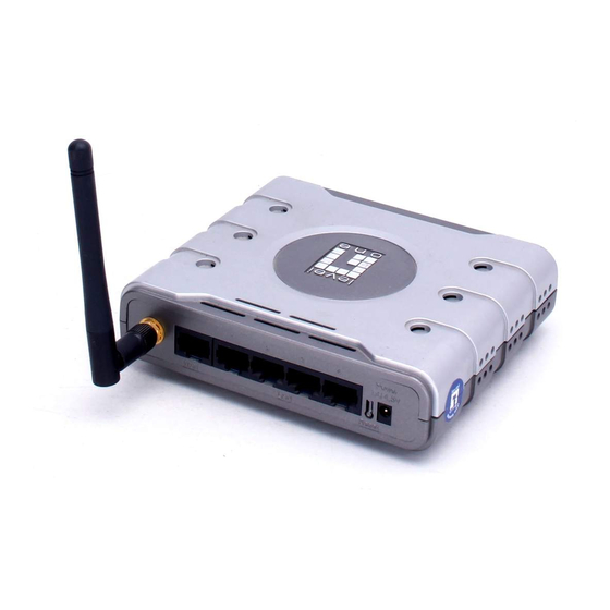
Introduction Rear Panel Figure 3: Rear Panel One 2 dbi antenna. Antenna Connect the DSL or Cable Modem here. If your modem came with a cable, use the supplied cable. Otherwise, use a standard LAN cable. Use standard LAN cables (RJ45 connectors) to connect your PCs to these ports. -
Page 11: Chapter 2 Installation
Chapter 2 Installation This Chapter covers the physical installation of the Wireless Router. Requirements Network cables. Use standard 10/100BaseT network (UTP) cables with RJ45 connectors. TCP/IP protocol must be installed on all PCs. For Internet Access, an Internet Access account with an ISP, and either of a DSL or Cable modem (for WAN port usage) ... - Page 12 Installation For best Wireless reception and performance, the Wireless Router should be positioned in a central location with mini- mum obstructions between the Wireless Router and the PCs. Also, if using multiple Access Points, adjacent Access Points should use different Channels. 2.
-
Page 13: Chapter 3 Setup
Chapter 3 Setup This Chapter provides Setup details of the Wireless Router. Overview This chapter describes the setup procedure for: Internet Access LAN configuration Wireless setup Assigning a Password to protect the configuration data. PCs on your local LAN may also require configuration. For details, see Chapter 4 - PC Configuration. -
Page 14: Configuration Program
Setup Configuration Program The Wireless Router contains an HTTP server. This enables you to connect to it, and configure it, using your Web Browser. Your Browser must support JavaScript. The configuration program has been tested on the following browsers: Netscape V4.08 or later ... - Page 15 Setup If you can't connect If the Wireless Router does not respond, check the following: The Wireless Router is properly installed, LAN connection is OK, and it is powered ON. You can test the connection by using the "Ping" com- mand: ...
-
Page 16: Setup Wizard
Setup Setup Wizard The first time you connect to the Wireless Router, the Setup Wizard will run automati- cally. (The Setup Wizard will also run if the Wireless Router's default settings are restored.) 1. Step through the Wizard until finished. ... - Page 17 Setup PPTP PPTP is mainly used in Server IP Address. Europe. User name and pass- word. You connect to the ISP only when required. The IP IP Address allocated to address is usually allocated you, if Static (Fixed). automatically, but may be Static (Fixed).
-
Page 18: Home Screen
Setup Home Screen After finishing the Setup Wizard, you will see the Home screen. When you connect in future, you will see this screen when you connect. An example screen is shown below. Figure 5: Home Screen Navigation & Data Input ... -
Page 19: Lan Screen
Setup LAN Screen Use the LAN link on the main menu to reach the LAN screen. An example screen is shown below. Figure 6: LAN Screen Data - LAN Screen TCP/IP IP address for the Wireless Router, as seen from the local LAN. IP Address Use the default value unless the address is already in use or your LAN is using a different IP address range. - Page 20 Setup Buttons Save any changes you have made. Note that if you change the Save Wireless Router's IP address, your connection will be lost. You will have to re-connect using the new IP address. Cancel The "Cancel" button will discard any data you have entered and reload the file from the Wireless Router.
-
Page 21: Wireless Screen
Setup Wireless Screen The Wireless Router's settings must match the other Wireless stations. Note that the Wireless Router will automatically accept both 802.11b and 802.11g connections, and no configuration is required for this feature. To change the Wireless Router's default settings for the Wireless Access Point fea- ture, use the Wireless link on the main menu to reach the Wireless screen. - Page 22 Setup Data - Wireless Screen Identification Select your region from the drop-down list. This field displays the Region region of operation for which the wireless interface is intended. It may not be legal to operate the router in a region other than the region shown here.
- Page 23 Setup MAC Access Control All Wireless Stations - All wireless stations can use the Allow LAN access point to access your LAN. access Selected Wireless stations only - Only selected wireless stations access your LAN. To select the required wireless stWations, click the "Select Stations"...
-
Page 24: Wireless Security Screen
Setup Wireless Security Screen This screen is accessed by clicking the "Configure" button on the Wireless screen. There are 3 options for Wireless security: Disabled - no data encryption is used. WEP - data is encrypted using the WEP standard. ... - Page 25 Setup Wireless Security - WPA/WPA2-PSK If "WPA1/2-PSK" is selected, the screen will look like the following example. Figure 9: WPA/WPA2-PSK Screen Data - WPA/WPA2-PSK screen Select the desired option: Authentication WPA-PSK: Like WEP, data is encrypted before transmis- sion. WPA is more secure than WEP, and should be used if possible.
- Page 26 Setup Wireless Distribution System Setup (WDS) Click WDS Setup on the Wireless screen to view a screen like the following. Figure 10: Wireless Distribution System Setup Screen Data - WDS Setup Screen Tick to Enable WDS. Enable WDS Enter the MAC Addresses of the Access Points or Routers you Allow Device wish to inter-connect.
- Page 27 Setup WDS Environment Below is an example of how a WDS operates. Figure 111: Wireless Distribution System 1. AP1, AP2 and AP3 are configured to use the same Channel and Security set- tings. 2. Enter AP2 and AP3’s MAC addresses into AP1’s WDS MAC Address list. 3.
- Page 28 Setup Wi-Fi Protected Setup Click Wi-Fi Protected Setup on the Wireless screen to view a screen like the following. Figure 12: Wi-Fi Protected Setup Screen Data - Wi-Fi Protected Setup Screen WPS PIN Input Enrol- Enter the PIN code and click Add Client to AP to add the client lee’s PIN device.
-
Page 29: Password Screen
Setup Password Screen The password screen allows you to assign a password to the Wireless Router. Figure 13: Password Screen Once you have assigned a password to the Wireless Router (on the Password screen above) you will be prompted for the password when you connect, as shown below. (If no password has been set, this dialog will not appear.) Figure 12: Password Dialog ... -
Page 30: Chapter 4 Pc Configuration
Chapter 4 PC Configuration This Chapter details the PC Configuration required on the local ("Inter- nal") LAN. Overview For each PC, the following may need to be configured: TCP/IP network settings Internet Access configuration Wireless configuration Windows Clients This section describes how to configure Windows clients for Internet access via the Wireless Router. - Page 31 PC Configuration Checking TCP/IP Settings - Windows 9x/ME: 1. Select Control Panel - Network. You should see a screen like the following: Figure 15: Network Configuration 2. Select the TCP/IP protocol for your network card. 3. Click on the Properties button. You should then see a screen like the following. Figure 16: IP Address (Win 95) Ensure your TCP/IP settings are correct, as follows: Using DHCP...
- Page 32 PC Configuration On the Gateway tab, enter the Wireless Router's IP address in the New Gateway field and click Add, as shown below. Your LAN administrator can advise you of the IP Address they assigned to the Wireless Router. Figure 17: Gateway Tab (Win 95/98) ...
- Page 33 PC Configuration Checking TCP/IP Settings - Windows NT4.0 1. Select Control Panel - Network, and, on the Protocols tab, select the TCP/IP protocol, as shown below. Figure 19: Windows NT4.0 - TCP/IP 2. Click the Properties button to see a screen like the one below.
- Page 34 PC Configuration Figure 20: Windows NT4.0 - IP Address 3. Select the network card for your LAN. 4. Select the appropriate radio button - Obtain an IP address from a DHCP Server or Specify an IP Address, as explained below. Obtain an IP address from a DHCP Server This is the default Windows setting.
- Page 35 PC Configuration Figure 21 - Windows NT4.0 - Add Gateway 2. The DNS should be set to the address provided by your ISP, as follows: Click the DNS tab. On the DNS screen, shown below, click the Add button (under DNS Service Search Order), and enter the DNS provided by your ISP.
- Page 36 PC Configuration Figure 22: Windows NT4.0 - DNS...
- Page 37 PC Configuration Checking TCP/IP Settings - Windows 2000: 1. Select Control Panel - Network and Dial-up Connection. 2. Right - click the Local Area Connection icon and select Properties. You should see a screen like the following: Figure 23: Network Configuration (Win 2000) 3.
- Page 38 PC Configuration Figure 24: TCP/IP Properties (Win 2000) 5. Ensure your TCP/IP settings are correct, as described below. Using DHCP To use DHCP, select the radio button Obtain an IP Address automatically. This is the default Windows setting. Using this is recommended. By default, the Wireless Rou- ter will act as a DHCP Server.
- Page 39 PC Configuration Checking TCP/IP Settings - Windows XP 1. Select Control Panel - Network Connection. 2. Right click the Local Area Connection and choose Properties. You should see a screen like the following: Figure 25: Network Configuration (Windows XP) 3. Select the TCP/IP protocol for your network card. 4.
- Page 40 PC Configuration Figure 26: TCP/IP Properties (Windows XP) 5. Ensure your TCP/IP settings are correct. Using DHCP To use DHCP, select the radio button Obtain an IP Address automatically. This is the default Windows setting. Using this is recommended. By default, the Wireless Rou- ter will act as a DHCP Server.
- Page 41 PC Configuration Internet Access To configure your PCs to use the Wireless Router for Internet access: Ensure that the DSL modem, Cable modem, or other permanent connection is functional. Use the following procedure to configure your Browser to access the Internet via the LAN, rather than by a Dial-up connection.
-
Page 42: Macintosh Clients
PC Configuration Macintosh Clients From your Macintosh, you can access the Internet via the Wireless Router. The proce- dure is as follows. 1. Open the TCP/IP Control Panel. 2. Select Ethernet from the Connect via pop-up menu. 3. Select Using DHCP Server from the Configure pop-up menu. The DHCP Client ID field can be left blank. -
Page 43: Wireless Station Configuration
The mode must be set to Infrastructure. This must match the value used on the Wireless Router. The SSID (ESSID) default value is WBR-3408 Note! The SSID is case sensitive. By default, Wireless security on the Wireless Router is disabled. -
Page 44: Chapter 5 Operation And Status
Chapter 5 Operation and Status This Chapter details the operation of the Wireless Router and the sta- tus screens. Operation Once both the Wireless Router and the PCs are configured, operation is auto- matic. However, there are some situations where additional Internet configuration may be required: ... -
Page 45: Status Screen
Operation and Status Status Screen Use the Status link on the main menu to view this screen. Figure 27: Status Screen Data - Status Screen Internet Connection Method This indicates the current connection method, as set in the Setup Wizard or WAN Port screen. This shows the status of the connection from the Wireless Broadband Modem Router to the Broadband Modem. - Page 46 Operation and Status The IP Address of the Wireless Router. IP Address The Network Mask (Subnet Mask) for the IP Address Network Mask above. This shows the status of the DHCP Server function - either DHCP Server "Enabled" or "Disabled". For additional information about the PCs on your LAN, and the IP addresses allocated to them, use the PC Database option on the Administration menu.
-
Page 47: Connection Status - Pppoe
Operation and Status Connection Status - PPPoE If using PPPoE (PPP over Ethernet), a screen like the following example will be dis- played when the "Connection Details" button is clicked. Figure 28: PPPoE Status Screen Data - PPPoE Screen Connection The hardware address of this device, as seen by remote Physical Address devices on the Internet. - Page 48 Operation and Status The most common messages are listed in the table below. The "Clear Log" button will restart the Log, while the Refresh button will update the messages shown on screen. Buttons If not connected, establish a connection to your ISP. Connect If connected to your ISP, hang up the connection.
-
Page 49: Connection Status - Pptp
Operation and Status Connection Status - PPTP If using PPTP (Peer-to-Peer Tunneling Protocol), a screen like the following example will be displayed when the "Connection Details" button is clicked. Figure 29: PPTP Status Screen Data - PPTP Screen Connection The hardware address of this device, as seen by remote devic- Physical Ad- es on the Internet. -
Page 50: Connection Status - L2Tp
Operation and Status Connection Log The Connection Log shows status messages relating to the Connection Log existing connection. The "Clear Log" button will restart the Log, while the Re- fresh button will update the messages shown on screen. Buttons If not connected, establish a connection to your ISP. - Page 51 Operation and Status Data - L2TP Screen Internet The hardware address of this device, as seen by remote devic- Physical Ad- es on the Internet. (This is different to the hardware address dress seen by devices on the local LAN.) The IP Address of this device, as seen by Internet users.
-
Page 52: Connection Status - Telstra Big Pond
Operation and Status Connection Status - Telstra Big Pond An example screen is shown below. Figure 31: Telstra Big Pond Status Screen Data - Big Pond Screen Connection The hardware address of this device, as seen by remote Physical Address devices. -
Page 53: Connection Details - Singtel Ras
Operation and Status Buttons If not connected, establish a connection to Telstra Big Pond. Connect If connected to Telstra Big Pond, terminate the connection. Disconnect Delete all data currently in the Log. This will make it easier to Clear Log read new messages. - Page 54 Operation and Status This will show "Enabled" or "Disabled". DHCP Client If "Enabled", the Internet IP Address from your ISP is allocated automatically upon connection. (Dynamic IP Ad- dress). In this case the "Lease obtained" and "Remaining lease time" fields provide additional information. Note that the lease is automatically renewed on expiry;...
-
Page 55: Connection Details - Fixed/Dynamic Ip Address
Operation and Status Connection Details - Fixed/Dynamic IP Address If your access method is "Direct" (no login), a screen like the following example will be displayed when the "Connection Details" button is clicked. Figure 33: Connection Details - Fixed/Dynamic IP Address Data - Fixed/Dynamic IP address Screen Internet The hardware address of this device, as seen by remote devic-... - Page 56 Operation and Status Buttons This button is only useful if the IP address shown above is Release/Renew allocated automatically on connection. (Dynamic IP ad- dress). Otherwise, it has no effect. This button will say "Release" if the Wireless Router is currently using an IP Address allocated by the ISP's DHCP Server.
-
Page 57: Chapter 6 Advanced Features
Chapter 6 Advanced Features This Chapter explains when and how to use the Wireless Router's "Ad- vanced" Features. Overview The following advanced features are provided. Access Control Dynamic DNS Internet Communication Applications Special Applications Multi-DMZ ... - Page 58 Advanced Features Access Control Screen To view this screen, select the Access Control link on the Advanced menu. Figure 34: Access Control Screen Data - Access Control Screen User Group Select Group Select the desired Group. The screen will update to display the settings for the selected Group.
-
Page 59: Services Screen
Advanced Features Block by Schedule If Internet access is being blocked, you can choose to apply the blocking only during scheduled times. (If access is not blocked, no Scheduling is possible, and this setting has no effect.) This lists all defined Services. Select the Services you wish to Services block. -
Page 60: Access Control Log
Advanced Features Data - Services Screen Available Services This lists all the available services. Available Ser- vices "Delete" button Use this to delete the selected Service from the list. Add New Service Enter a descriptive name to identify this service. Name Select the correct type for this Service. -
Page 61: Dynamic Dns (Domain Name Server)
Advanced Features Dynamic DNS (Domain Name Server) This free service is very useful when combined with the Virtual Server feature. It allows Internet users to connect to your Virtual Servers using a URL, rather than an IP Ad- dress. This also solves the problem of having a dynamic IP address. With a dynamic IP address, your IP address may change whenever you connect, which makes it difficult to connect to you. - Page 62 Advanced Features Data - Dynamic DNS Screen DDNS Data Select the desired DDNS Service provider. To disable DDNS, DDNS Service select "None". DDNS Status This message is returned by the DDNS Server. Normally, this message should be something like "Update successful"...
-
Page 63: Advanced Internet Screen
Advanced Features Advanced Internet Screen This screen allows configuration of all advanced features relating to Internet access. Communication Applications Special Applications Multi-DMZ An example screen is shown below. Figure 37: Internet Screen Communication Applications Most applications are supported transparently by the Wireless Router. But sometimes it is not clear which PC should receive an incoming connection. -
Page 64: Special Applications
Advanced Features This lists the PCs on your LAN. Send incoming calls to If necessary, you can add PCs manually, using the "PC Database" option on the advanced menu. For each application listed above, you can choose a destination PC. -
Page 65: Using A Special Application
Advanced Features Data - Special Applications Screen Enter a descriptive name to identify this Special Application. Name Type - Select the protocol (TCP or UDP) used when you receive Incoming data from the special application or service. (Note: Some applica- Ports tions use different protocols for outgoing and incoming data). - Page 66 Advanced Features Multi-DMZ This feature, if enabled, allows the DMZ computer or computers on your LAN to be exposed to all users on the Internet. This allows almost any application to be used on the "DMZ PC". The "DMZ PC" will receive all "Unknown" connections and data. ...
-
Page 67: Url Filter
Advanced Features URL Filter The URL Filter allows you to block access to undesirable Web site To use this feature, you must define "filter strings". If the "filter string" appears in a requested URL, the request is blocked. Enabling the URL Filter also affects the Internet Access Log. - Page 68 Advanced Features Filter Strings This lists any existing entries. If you have not entered any values, Filter Strings this list will be empty. Use this to delete the selected entry or entries, as required. Delete Multiple entries can be selected by holding down the CTRL key while selecting.
-
Page 69: Define Schedule
Advanced Features Define Schedule The schedule can be used for the Access Control and URL Filter features. Two (2) separate sessions or periods can be defined. Times must be entered using a 24 hr clock. If the time for a particular day is blank, no action will be performed. Figure 41: Define Schedule Screen Data –... -
Page 70: User Groups
Advanced Features User Groups User Groups are used by the Access Control and the URL Filter features. Groups are pre-named "Default", "Group 1", "Group 2", "Group 3" and "Group 4", and cannot be renamed. All PCs are in the "Default" group, unless moved to another group. ... -
Page 71: Virtual Servers
Advanced Features Virtual Servers This feature, sometimes called Port Forwarding, allows you to make Servers on your LAN accessible to Internet users. Normally, Internet users would not be able to access a server on your LAN because: Your Server does not have a valid external IP Address. ... - Page 72 Advanced Features Figure 44: Virtual Servers Screen This screen lists a number of pre-defined Servers, and allows you to define your own Servers. Details of the selected Server are shown in the "Properties" area. Data - Virtual Servers Screen Servers This lists a number of pre-defined Servers, plus any Servers Servers you have defined.
-
Page 73: Defining Your Own Virtual Servers
Advanced Features Buttons Delete the current Virtual Server entry. Note that the pre- Delete defined Servers can not be deleted. Only Servers you have defined yourself can be deleted. This will delete any Servers you have defined, and set the Defaults pre-defined Servers to use their default port numbers. -
Page 74: Connecting To The Virtual Servers
Advanced Features Connecting to the Virtual Servers Once configured, anyone on the Internet can connect to your Virtual Servers. They must use the Internet IP Address (the IP Address allocated to you by your ISP). e.g. http://203.70.212.52 ftp://203.70.212.52 It is more convenient if you are using a Fixed IP Address from your ISP, rather than Dynamic. -
Page 75: Wan Port Configuration
Advanced Features WAN Port Configuration The WAN Port option is on the Advanced menu. Figure 45: WAN Port Screen Data - WAN Port Screen MTU (Maximum Transmission Unit) value should only be MTU Size changed if advised to do so by Technical Support. ... - Page 76 Advanced Features Also called Network Adapter Address or Physical Address. This MAC Address is a low-level identifier, as seen from the WAN port. Normally there is no need to change this, but some ISPs re- quire a particular value, often that of the PC initially used for Internet access.
- Page 77 Advanced Features Login Login Method If your ISP does not use a login method (username, password) for Internet access, leave this at the default value None (Direct connection). Otherwise, check the documentation from your ISP, select the login method used, and enter the required data. ...
- Page 78 Advanced Features Buttons Default Inserts the default MAC address into the MAC address field. You must click "Save" to actually change the address used. Inserts the MAC address from your PC into the MAC address Copy from PC field. You must click "Save" to actually change the address used.
-
Page 79: Chapter 7 Advanced Administration
Chapter 7 Advanced Administration This Chapter explains the settings available via the "Administration" section of the menu. Overview Normally, it is not necessary to use these screens, or change any settings. These screens and settings are provided to deal with non-standard situations, or to provide additional options for advanced users. -
Page 80: Config File
Advanced Administration Config File This feature allows you to download the current settings from the Wireless Router, and save them to a file on your PC. You can restore a previously-downloaded configuration file to the Wireless Router, by uploading it to the Wireless Router. This screen also allows you to set the Wireless Router back to its factory default configuration. -
Page 81: Logs
Advanced Administration Logs The Logs record various types of activity on the Wireless Router. This data is useful for troubleshooting, but enabling all logs will generate a large amount of data and adverse- ly affect performance. Since only a limited amount of log data can be stored in the Wireless Router, log data can also be E-mailed to your PC. - Page 82 Advanced Administration Select the correct Timezone for your location. This is re- Timezone quired for the date/time shown on the logs to be correct. View Log button Use this to view each log, as required. Use this to restart the required log. This makes it easier to Clear Log button read the latest entries.
-
Page 83: Network Diagnostics
Advanced Administration Network Diagnostics This screen allows you to perform a "Ping" or a "DNS lookup". These activities can be useful in solving network problems. An example Network Diagnostics screen is shown below. Figure 48: Network Diagnostics Screen Data - Network Diagnostics Screen Ping Enter the IP address you wish to ping. -
Page 84: Options
Advanced Administration Options This screen allows advanced users to enter or change a number of settings. For normal operation, there is no need to use this screen or change any settings. An example Options screen is shown below. Figure 49: Options Screen Data - Options Screen Backup DNS Enter the IP Address of the DNS (Domain Name Servers) here. -
Page 85: Pc Database
Advanced Administration PC Database The PC Database is used whenever you need to select a PC (e.g. for the "DMZ" PC). It eliminates the need to enter IP addresses. Also, you do not need to use fixed IP addresses on your LAN. PC Database Screen An example PC Database screen is shown below. - Page 86 Advanced Administration Data - PC Database Screen Known PCs This lists all current entries (PCs or network devices). If adding a new PC to the list, enter its name here. It is best if this Name matches the PC's "hostname". If adding a new PC to the list, enter the IP Address of the PC IP Address here.
- Page 87 Advanced Administration Advanced PC Database This screen is displayed if the "Advanced" button on the PC Database is clicked. It provides more control than the standard PC Database screen. Figure 51: Advanced PC Database Data - Advanced PC Database Screen This lists all current entries (PCs or network devices).
- Page 88 Advanced Administration Select the appropriate option: IP Address Automatic - The PC is set to be a DHCP client (Windows: "Obtain an IP address automatically"). The Wireless Router will allocate an IP address to this PC when requested to do so.
-
Page 89: Remote Admin
Advanced Administration Remote Admin If enabled, this feature allows you to manage the Wireless Router via the Internet. Figure 52: Remote Administration Screen Data - Remote Administration Screen Remote Administration Check to allow administration/management via the Internet. (To Enable Remote connect, see below). - Page 90 Advanced Administration Have your ISP allocate you a Fixed IP address. Use the DDNS feature (Advanced menu) so you can connect using a Domain Name, rather than an IP address. To connect from a remote PC via the Internet 1.
-
Page 91: Routing
Advanced Administration Routing Overview If you don't have other Routers or Gateways on your LAN, you can ignore the "Routing" page completely. If the Wireless Router is only acting as a Gateway for the local LAN segment, ignore the "Routing" page even if your LAN has other Routers. ... - Page 92 Advanced Administration Figure 53: Routing Screen Data - Routing Screen Check this to enable the RIP (Routing Information Protocol) Enable RIP VI feature of the Wireless Router. The Wireless Router supports RIP 1 only. Static Routing This list shows all entries in the Routing Table. Static Routing Table Entries ...
-
Page 93: Configuring Other Routers On Your Lan
Advanced Administration Destination Network - The network address of the remote Properties LAN segment. For standard class "C" LANs, the network address is the first 3 fields of the Destination IP Address. The 4th (last) field can be left at 0. ... - Page 94 Advanced Administration Other Routers on the Local LAN Other routers on the local LAN must use the Wireless Router's Local Router as the Default Route. The entries will be the same as the Wireless Router's local router, with the exception of the Gateway IP Address. ...
- Page 95 Advanced Administration For Router A's Default Route Destination IP Address 0.0.0.0 Network Mask 0.0.0.0 Gateway IP Address 192.168.0.1 (Wireless Router's IP Ad- dress) For Router B's Default Route Destination IP Address 0.0.0.0 Network Mask 0.0.0.0 Gateway IP Address 192.168.1.80 (Wireless Router's local router)
-
Page 96: Security
Advanced Administration Security This screen allows you to set Firewall and other security-related options. Figure 55: Security Screen Data - Security Screen DoS Firewall If enabled, DoS (Denial of Service) attacks will be detected and Enable DoS blocked. The default is enabled. It is strongly recommended that Firewall this setting be left enabled. - Page 97 Advanced Administration The IPSec, PPTP, and L2TP protocols are used to establish a Allow VPN secure connection, and are widely used by VPN (Virtual Private Pass through Networking) programs. If checked, these VPN connections are allowed. If not checked, these VPN connections are blocked. Note: IPSec sessions must NOT use AH (Authentication Head- er).
-
Page 98: Upgrade Firmware
Advanced Administration Upgrade Firmware The firmware (software) in the Wireless Router can be upgraded using your Web Browser. You must first download the upgrade file, then select Upgrade on the Administration menu. You will see a screen like the following. Figure 56: Upgrade Firmware Screen To perform the Firmware Upgrade: 1. -
Page 99: Appendix A Troubleshooting
Appendix A Troubleshooting This Appendix covers the most likely problems and their solutions. Overview This chapter covers some common problems that may be encountered while using the Wireless Router and some possible solutions to them. If you follow the suggested steps and the Wireless Router still does not function properly, contact your dealer for further advice. -
Page 100: Wireless Access
Appendix A - Troubleshooting Problem 2: Some applications do not run properly when using the Wireless Router. The Wireless Router processes the data passing through it, so it is Solution 2: not transparent. Use the Special Applications feature to allow the use of Internet applications which do not function correctly. - Page 101 Appendix A - Troubleshooting devices should be shielded or relocated. RF Shielding Your environment may tend to block transmission between the wireless stations. This will mean high access speed is only possi- ble when close to the Wireless Router.
-
Page 102: Appendix B About Wireless Lans
Appendix B About Wireless LANs This Appendix provides some background information about using Wireless LANs (WLANs). Modes Wireless LANs can work in either of two (2) modes: Ad-hoc Infrastructure Ad-hoc Mode Ad-hoc mode does not require an Access Point or a wired (Ethernet) LAN. Wire- less Stations (e.g. -
Page 103: Channels
Appendix B - About Wireless LANs Channels The Wireless Channel sets the radio frequency used for communication. Access Points use a fixed Channel. You can select the Channel used. This allows you to choose a Channel which provides the least interference and best perfor- mance. -
Page 104: Wpa2-Psk
Appendix B - About Wireless LANs WPA2-PSK This is a later version of WPA (WPA-PSK). The major change is the use of AES (Advanced Encryption System) for protecting data. AES is very secure, considered to be unbreakable. The PSK (Pre-shared Key) must be entered on each Wireless station. If WPA2-PSK is used, the Wireless Stations and the Access Point must have the same settings for each of the following: Enter the same value on every station and the AP. -
Page 105: Appendix C Specifications
Appendix C Specifications Wireless Router Model WBR-3408 Dimensions 125mm(W) * 110mm(D) * 34mm(H) Operating Tempera- 0 C to 40 C ture Storage Temperature -20 C to 70 C Network Protocol: TCP/IP Network Interface: 5 Ethernet: 4 * 10/100BaseT (RJ45) LAN connection...
Need help?
Do you have a question about the wbr-3408 and is the answer not in the manual?
Questions and answers